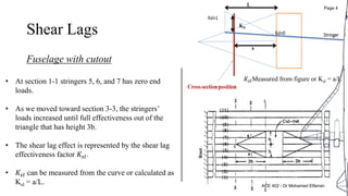
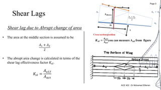
Shear Lags
In general shear lag results from the effect of sheet panels shear stress
that cause some stringers to resist fewer axial loads than those
calculated using the beam theory.
The shear lag effect is significant for:
1. Cutouts.
2. Abrupt change of area.
3. Large abrupt change in external loads.
ACE 402 - Dr Mohamed Elfarran
Page 2
Shear Lags
Assume three stringers as shown in figure
Cutout
ACE 402 - Dr Mohamed Elfarran
Page 3
Shear Lags
Fuselage with cutout
• At section 1-1 stringers 5, 6, and 7 has zero end
loads.
• As we moved toward section 3-3, the stringers’
loads increased until full effectiveness out of the
triangle that has height 3b.
• The shear lag effect is represented by the shear lag
effectiveness factor 𝐾𝑠𝑙.
• 𝐾𝑠𝑙 can be measured from the curve or calculated as
Ksl = a/L.
𝐾𝑠𝑙Measured from figure or Ksl = a/L
ACE 402 - Dr Mohamed Elfarran
Page 4
Shear Lags
Shear lag due to Abrupt change of area
𝑲 𝒔𝒍 =
𝑨 𝒆𝒇𝒇
𝑨 𝒂𝒄𝒕
you can measure Aeff from figure
𝐴1 + 𝐴2
2
• The area at the middle section is assumed to be
• The abrupt area change is calculated in terms of the
shear lag effectiveness factor 𝐾𝑠𝑙.
𝐾𝑠𝑙 =
𝐴 𝑒𝑓𝑓
𝐴 𝑎𝑐𝑡
𝐴1 + 𝐴2
2
ACE 402 - Dr Mohamed Elfarran
Page 5
Wing stress analysis – Procedure
1. Calculate the inter-rivet buckling of the skin which under compression (upper, left and right skin).
2. Calculate the crippling stress of the corner stringers under compression.
3. Calculate the column failure stress of the inter-mediate stringers that are supported from one edge.
4. Calculate the sheet effective width for each stringer. (w)
5. Calculate the corrected effective width for each stringer under compression.
𝒘 𝒄𝒐𝒓 = 𝒘
𝑭𝒊𝒓
𝑭 𝒄𝒔
6. Calculate the total effective area of each stringer in both compression and tension sides.
7. Calculate the effective correction factor for the upper stringers under compression and for the lower
stringers it equal 1.
𝑲 𝒆𝒇𝒇 =
𝑭 𝒄
𝑭 𝒄𝒔
8. Calculate the shear-lag factor.
ACE 402 - Dr Mohamed Elfarran
Page 6
Wing stress analysis
– Procedure
1 Calculate the effective area
𝐴 𝑒𝑓𝑓 = 𝐾𝑒𝑓𝑓 𝐾𝑠𝑙 𝐴𝑡
2 Measure the coordinates of the existing areas 𝑥′
𝑎𝑛𝑑 𝑧,
and calculate the centroid position.
𝑍𝑐 =
𝐴𝑧′
𝐴
& 𝑋𝑐 =
𝐴𝑥′
𝐴
3 Calculate the second moments of area.
𝐼𝑥𝑥 = 𝐴𝑍2
, 𝐼𝑧𝑧 = 𝐴𝑋2
, 𝐼𝑥𝑧 = 𝐴𝑍𝑋
4 Calculate the applying bending moment
This bending moment depend on the type of the distributed load or the concentrated force
5 Calculate the resultant bending stress.
𝝈 𝒃 = − 𝑲 𝟑 𝑴 𝒛 − 𝑲 𝟏 𝑴 𝒙 𝑿 − 𝑲 𝟐 𝑴 𝒙 − 𝑲 𝟏 𝑴 𝒛 𝒁
2𝑙𝑝
3
3𝑙
8
𝑙 p
𝑙𝑝
3
𝑙
4
𝑙
p
𝑙𝑝
2
𝑙
3
𝑙
p
Where
𝑲 𝟏 =
𝑰 𝒙𝒛
𝑰
, 𝑲 𝟐 =
𝑰 𝒛𝒛
𝑰
, 𝑲 𝟑 =
𝑰 𝒙𝒙
𝑰
, 𝑰 = 𝑰 𝒙𝒙 𝑰 𝒛𝒛 − 𝑰 𝒙𝒛
𝟐
For symmetric wing then
𝑴 𝒛 = 𝟎, 𝑰 𝒙𝒛 = 𝟎
and
𝝈 𝒃 =
−𝑴 𝒙
𝑰 𝒙
𝒁
1 The margin of safety
𝑴𝑺 =
𝝈 𝒇𝒂𝒊𝒍𝒖𝒓𝒆
𝝈𝒕𝒓𝒖𝒆
− 𝟏
ACE 402 - Dr Mohamed Elfarran
Page 7

Ace 402 Airframe Design and Construction lec 9

  • 2.
    Shear Lags In generalshear lag results from the effect of sheet panels shear stress that cause some stringers to resist fewer axial loads than those calculated using the beam theory. The shear lag effect is significant for: 1. Cutouts. 2. Abrupt change of area. 3. Large abrupt change in external loads. ACE 402 - Dr Mohamed Elfarran Page 2
  • 3.
    Shear Lags Assume threestringers as shown in figure Cutout ACE 402 - Dr Mohamed Elfarran Page 3
  • 4.
    Shear Lags Fuselage withcutout • At section 1-1 stringers 5, 6, and 7 has zero end loads. • As we moved toward section 3-3, the stringers’ loads increased until full effectiveness out of the triangle that has height 3b. • The shear lag effect is represented by the shear lag effectiveness factor 𝐾𝑠𝑙. • 𝐾𝑠𝑙 can be measured from the curve or calculated as Ksl = a/L. 𝐾𝑠𝑙Measured from figure or Ksl = a/L ACE 402 - Dr Mohamed Elfarran Page 4
  • 5.
    Shear Lags Shear lagdue to Abrupt change of area 𝑲 𝒔𝒍 = 𝑨 𝒆𝒇𝒇 𝑨 𝒂𝒄𝒕 you can measure Aeff from figure 𝐴1 + 𝐴2 2 • The area at the middle section is assumed to be • The abrupt area change is calculated in terms of the shear lag effectiveness factor 𝐾𝑠𝑙. 𝐾𝑠𝑙 = 𝐴 𝑒𝑓𝑓 𝐴 𝑎𝑐𝑡 𝐴1 + 𝐴2 2 ACE 402 - Dr Mohamed Elfarran Page 5
  • 6.
    Wing stress analysis– Procedure 1. Calculate the inter-rivet buckling of the skin which under compression (upper, left and right skin). 2. Calculate the crippling stress of the corner stringers under compression. 3. Calculate the column failure stress of the inter-mediate stringers that are supported from one edge. 4. Calculate the sheet effective width for each stringer. (w) 5. Calculate the corrected effective width for each stringer under compression. 𝒘 𝒄𝒐𝒓 = 𝒘 𝑭𝒊𝒓 𝑭 𝒄𝒔 6. Calculate the total effective area of each stringer in both compression and tension sides. 7. Calculate the effective correction factor for the upper stringers under compression and for the lower stringers it equal 1. 𝑲 𝒆𝒇𝒇 = 𝑭 𝒄 𝑭 𝒄𝒔 8. Calculate the shear-lag factor. ACE 402 - Dr Mohamed Elfarran Page 6
  • 7.
    Wing stress analysis –Procedure 1 Calculate the effective area 𝐴 𝑒𝑓𝑓 = 𝐾𝑒𝑓𝑓 𝐾𝑠𝑙 𝐴𝑡 2 Measure the coordinates of the existing areas 𝑥′ 𝑎𝑛𝑑 𝑧, and calculate the centroid position. 𝑍𝑐 = 𝐴𝑧′ 𝐴 & 𝑋𝑐 = 𝐴𝑥′ 𝐴 3 Calculate the second moments of area. 𝐼𝑥𝑥 = 𝐴𝑍2 , 𝐼𝑧𝑧 = 𝐴𝑋2 , 𝐼𝑥𝑧 = 𝐴𝑍𝑋 4 Calculate the applying bending moment This bending moment depend on the type of the distributed load or the concentrated force 5 Calculate the resultant bending stress. 𝝈 𝒃 = − 𝑲 𝟑 𝑴 𝒛 − 𝑲 𝟏 𝑴 𝒙 𝑿 − 𝑲 𝟐 𝑴 𝒙 − 𝑲 𝟏 𝑴 𝒛 𝒁 2𝑙𝑝 3 3𝑙 8 𝑙 p 𝑙𝑝 3 𝑙 4 𝑙 p 𝑙𝑝 2 𝑙 3 𝑙 p Where 𝑲 𝟏 = 𝑰 𝒙𝒛 𝑰 , 𝑲 𝟐 = 𝑰 𝒛𝒛 𝑰 , 𝑲 𝟑 = 𝑰 𝒙𝒙 𝑰 , 𝑰 = 𝑰 𝒙𝒙 𝑰 𝒛𝒛 − 𝑰 𝒙𝒛 𝟐 For symmetric wing then 𝑴 𝒛 = 𝟎, 𝑰 𝒙𝒛 = 𝟎 and 𝝈 𝒃 = −𝑴 𝒙 𝑰 𝒙 𝒁 1 The margin of safety 𝑴𝑺 = 𝝈 𝒇𝒂𝒊𝒍𝒖𝒓𝒆 𝝈𝒕𝒓𝒖𝒆 − 𝟏 ACE 402 - Dr Mohamed Elfarran Page 7