Downloaded 105 times


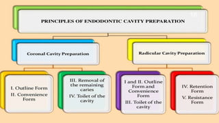


This document discusses the principles and procedures for access cavity preparation in endodontics, defining it as essential for unobstructed access to canal orifices and effective control during instrumentation. Key concepts include the anatomy of root canals, classification of canal systems, required instruments, and techniques for accessing various tooth types, while emphasizing the importance of avoiding iatrogenic errors. It also covers potential challenges, such as calcified canals and the management of teeth with minimal crowns, providing guidelines to optimize the endodontic treatment process.


