1) Vertical aboveground storage tanks are commonly used to store liquids and gases in processing facilities. They can have fixed roofs or floating roofs, and selection depends on factors like the stored material's true vapor pressure.
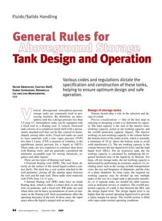
2) There are two main types of floating roof tanks: external floating roofs that float directly on the stored liquid, and internal floating roofs that float inside a fixed roof tank.
3) Proper design of storage tanks involves considerations for process parameters, mechanical design, environmental regulations, structural requirements, and other safety factors. Standards like those from API provide guidelines for design, construction, and operation.
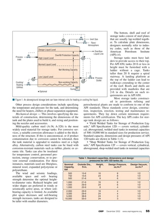


![5G Explained! A High Level Overview [Introduction]](https://cdn.slidesharecdn.com/ss_thumbnails/5gexplainedahighleveloverview-260119165306-cc137a3e-thumbnail.jpg?width=640&height=640&fit=bounds)