Download to read offline

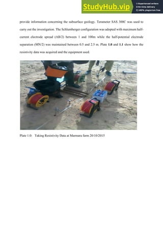
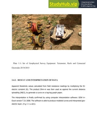


This technical report summarizes the student's industrial work experience with Concast Geological Nigeria Limited, located in Lafia, Nasarawa State. The student participated in geophysical surveys, borehole drilling, logging, and pump installation during their six-month attachment. Geophysical surveys such as electrical resistivity methods are used to determine suitable sites for productive boreholes. Once a site is identified, borehole drilling is conducted to access groundwater resources. The experience provided insights into effective borehole construction and design to ensure sustainable groundwater supply.