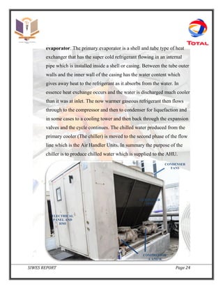
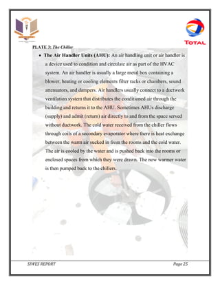
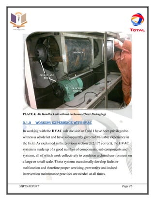
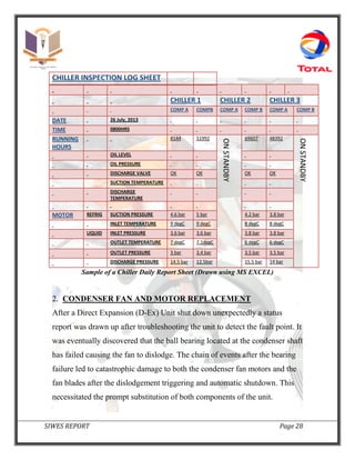
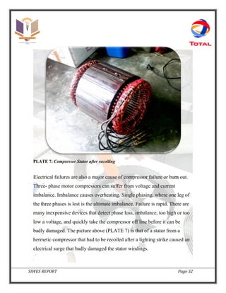
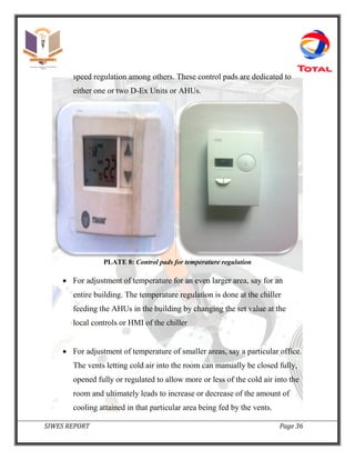
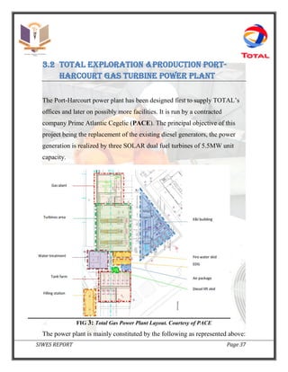
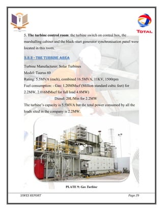
SIWES REPORT Page 1
INDUSTRIAL TRAINING REPORT
STUDENTS INDUSTRIAL TRAINING WORK EXPERIENCE SCHEME
2012/2013 ACADEMIC SESSION
MARCH 2013 – AUGUST 2013
BY
OKAFOR NNAMDI GABRIEL
2009244589
DEPARTMENT OF MECHANICAL ENGINEERING
FACULTY OF ENGINEERING
NNAMDI AZIKIWE UNIVERSITY, AWKA
ATTACHED TO
TOTAL EXPLORATION AND PRODUCTION
NIGERIA LIMITED
SEPTEMBER 2013.
SIWES REPORT Page 2
DEDICATION
This Technical Report is dedicated to my Heavenly Father. His Grace
and Love has been abundant indeed.
“But Jesus beheld them, and said unto them, with men this is
impossible; but with God all things are possible.”
Matthew 19: 26
SIWES REPORT Page 3
ACKNOWLEDGEMENT
I would like to show enormous gratitude to:
My parents Mr. & Mrs. Okafor. Relatives Mr. & Mrs. Muottoh and my
entire family for their support and well wishes through out my stay
at Port-Harcourt
My excellent supervisor at Total E&P Mr. Kolawole Muniru. He taught
me so much about life and about engineering.
Mr. Ugo Anslem, Coordinator at Prime Atlantic Cegelic (PACE) as
well as the entire team at the Gas Turbine Power plant. Working with
you was an outright blessing.
SIWES REPORT Page 4
TABLE OF CONTENTS
PAGE
Title Page 1
Dedication 2
Acknowledgement 3
Table of Contents 4
Abstract 6
Introduction 7
CHAPTER ONE
1.0 A brief history of SIWES 8
1.1 Objectives of SIWES 9
1.1.0 Mission and Vision 9
CHAPTER TWO
2.0 Overview of Total E&P Nigeria Limited 12
2.1 The Total Attitude 14
2.2 Departments and sub-divisions 15
CHAPTER THREE
SIWES REPORT Page 5
3.0 Involvement and work done 18
3.1 Heating ventilating & air conditioning 19
3.1.1 Composition & Operation Flow
Processes
20
3.1.2 Working experience with HVAC 26
3.2 Total E&P Port-Harcourt Gas turbine
Power Plant
37
3.2.1 The Technical Building 38
3.2.2 The Turbine Area 39
3.2.3 The Gas Treatment Station 40
3.2.4 The Utility Area 40
3.2.5 Control Systems 42
3.2.6 Working experience at the gas turbine
plant
44
CHAPTER FOUR
4.0 CONCLUSION 55
SIWES REPORT Page 6
ABSTRACT
The Student Industrial Work Experience Scheme (SIWES) in
conjunction with the Industrial Training Fund (ITF) and Nnamdi
Azikiwe University (NAU), Awka organized the Industrial Attachment
program having the sole objective of bridging the gap between
theory and practice among students in Tertiary Institutions. In
partial fulfilment of the requirements for the award of bachelor of
engineering degree I have actively participated in this program as
an Industrial Trainee at Total Exploration and Production Nigeria
Limited, Port Harcourt District. I worked in the department of Works
and Maintenance as well as the department of Energy and
throughout my stay in different work branches and subdivisions I
have gathered invaluable knowledge and experience with regard to
engineering operations, practices and principles which I have
carefully elaborated in the following report.
SIWES REPORT Page 7
INTRODUCTION
The Students Industrial Work Experience Scheme (SIWES) for the
2012/2013 academic session kicked off in the month of March 2013 and was
to be concluded six months later, August 2013. The Industrial Attachment
program is solely aimed at improving the working skills of students in
tertiary institutions as well as effecting learning, participation and
observation of the actual implementation of theories put into practice in
various fields with respect to programs and courses being studied in school.
This scheme serves as an opportunity for students to grasp very useful
practical knowledge which not only makes them employable but also aids in
the perfect understanding of theories and operations in their different majors.
The program is of very high importance considering the lack of adequate
practical materials for learning in most Nigerian tertiary institutions and is
self proven as it has been part and parcel of the country’s system of
education for over 25 years.
SIWES REPORT Page 8
CHAPTER ONE
1.0 A BRIEF HISTORY OF SIWES
SIWES was set up by the Federal Government of Nigeria to close the gap
between theoretical laws taught in the classroom and actual practice for
students in tertiary institutions. It was first kicked off and funded by the
Industrial Training Fund (ITF) between 1973 and 1974.
Since its introduction by the ITF in 1973 the Scheme has gone through series
of reforms. Its management has changed hands from the ITF in 1978 to
various regulatory agencies such as National Universities Commission
(NUC) and National board for Technical Education (NBTE) in 1979,
National Commission for college of Education (NCCE) and now back to the
ITF again in 1985.These are the major stakeholders in (SIWES).
Consequently, SIWES Program was introduced into the curriculum of
tertiary institutions in the country as far back as 1974 with 748 students from
11 institutions of higher learning and the scheme has over the years
contributed immensely to the personal development and motivation of
students to be able to understand the important connection between the
taught and learnt content of their academic programs and what knowledge
and skill will be expected of them on professional practice after graduation.
SIWES REPORT Page 9
1.1 OBJEC TIVES OF SIWES
The Industrial training funds policy document no. 1 of 1973, which
established SIWES outline the objectives of the scheme. The objectives are
to:
1. Provide an avenue for students in institution of higher learning to
acquire industrial skills and experience during their course of study.
2. Prepare students for industrial work situation that they are likely to
meet after graduation.
3. Expose students to work methods and techniques in handling
equipment and machinery that may not be available in their
institutions.
4. Make the transition from school to the world of work carrier and
enhances students contacts for later job placements.
5. Provide students with the opportunities to apply their educational
knowledge in real work situations, thereby bridging the gap between
theory and practical.
1.1.1 - MISSION AND VISION
SIWES Is charged with the responsibility of promoting and encouraging the
acquisition of skill, commerce and industry, with the view to generating a
pool of trained indigenous manpower sufficient to meet the need of the
economy. It is aimed at developing the human resources of the nation. It
builds the nation’s work force to promote the economy of a nation.
SIWES REPORT Page 10
The vision of SIWES is to prepare students to contribute to the productivity
of their nation. Students’ Industrial Work-Experience Scheme has the
potential of increasing the scope and variety of technical skills in the
common pool or general stock available for the industrial development of
Nigeria. Therefore, harnessing the potentials of SIWEs for Industrial,
technological and Economic development however demands that the three
major SIWES stakeholders or actors (students, institutions and employers)
be empowered to fully participate and cooperate with one another in
implanting the scheme. While such cooperation requires that, the three
actors share the same information on all basic aspects of SIWES.
BENEFITS OF INDUSTRIAL TRAINING TO STUDENTS
The major benefits accruing to students who participate conscientiously in
industrial training are the skills and competencies they acquire. This is
because the knowledge and skill acquired through training by students are
internalized, and it becomes relevant, during job performances or functions.
Several other benefits include:
1. Opportunity for students to blend theoretical knowledge acquired in
the classroom with practical hand-on application of knowledge
required to perform work in industry.
2. Exposes students to the working environment, i.e. to enable them see
how their professions are organized in practice.
3. Prepares students to contribute to the productivity of their employers
and nation’s economy.
SIWES REPORT Page 11
4. Provision of an enabling environment where students can develop and
enhance personal attributes such as critical thinking, creativity,
initiative, resourcefulness leadership, time management, presentation
of skills and interpersonal skills.
5. Prepares students for employment and makes transition from school to
the work environment easier after graduation.
6. Enables Students Bridge the gap between the acquired skills in the
institutions and the relevant production skill required in the work
organization.
7. Enhances students’ contact with potential employers while on
training.
SIWES REPORT Page 12
CHAPTER TWO
2.0 OVERVIEW OF TOTAL e&P NIGERIA
LIMITED
Total is one of the world’s major oil and gas groups with activities in more
than 130 countries. Its 95,000 employees put their expertise to work in every
part of the industry – exploration and production of oil and natural gas,
refining and marketing, gas trading and electricity. Total is working to keep
the world supplied with energy today and tomorrow. The Group is also a
first rank player in chemicals.
In Nigeria, the upstream activities of the Group are carried out by three
subsidiaries, Total Exploration & Production Nigeria Limited (TEPNG),
Total E&P Deepwater A to H Limited and Total Upstream Nigeria Limited
(TUPNI). TEPNG was incorporated under the laws of the Federal Republic
of Nigeria in May 1962 under the name SAFRAP, The group is also present
in the gas utilization program of the country through two other subsidiaries,
Total LNG Nigeria Limited with 15% equity in Nigerian Liquefied Natural
Gas (NLNG), and Brass Holdings Company Limited holding 17% shares in
the Brass LNG Project.
The main activities include exploration, development and production of oil
and gas while contributing to the development of communities where it
operates and their neighbours. In collaboration with international non-
governmental organisations (NGOs), the United Nations Development
SIWES REPORT Page 13
Programme (UNDP) and representatives of governments and local
communities, the company provides skills development for youths,
scholarship awards, upgrades of educational infrastructure, water supply,
electricity, health, roads, income generating projects and agriculture. The co-
operation between the company, government, local communities and NGOs,
is ongoing and more projects in line with its new vision on SD will be
undertaken in the coming years to ensure sustainable development of the
host communities.
SIWES REPORT Page 14
2.1 THE Total attitude
As is expected of every Nigerian citizen and of course every student Nnamdi
Azikiwe University certain behavioural patterns have to be upheld to foster
coexistence and general progress. The same exists in Total E&P.
Total has been unswerving to a set of laid down interior values that were
carved out and slowed developed by its founders and remain the cornerstone
of our corporate attitude. These values shape everything Total does as a
company and is never termed ‘relative to situation’ as it is widely respected
irrespective of the job at hand.
These are the four foundation behaviours that are expected of every Total
employee.
 Boldness - is about daring to think and act differently, challenging
conventional wisdom and refusing to follow established procedures.
 Mutual Support - is about developing trust, being loyal and always
looking for ways to help others.
 Listening - is about sharing your ideas, encouraging others to share
theirs and being attentive to the world around us.
 Cross Functionality - involves working and finding new solutions
together, leveraging the diversity within our organisation.
COMPANY ADDRESS
Total Exploration & Production Nigeria Limited has branches situated in Abuja, Lagos and Port-Harcourt.
SIWES REPORT Page 15
 Abuja Office: - TOTAL HOUSE II Plot 247, Herbert Macaulay Way, Central Business District, P.O. Box
11320 Garki District, Abuja.
 Lagos Office: - 35, Kofo Abayomi Street, Victoria Island. P.O. Box 927, Lagos.
 Port-Harcourt: - Plot 25, Trans Amadi Industrial layout, P.M.B 5160 and P.O. Box 696, Port-Harcourt.
2.2 Departments and sub-divisions
Total has over the years grown to be a gigantic organisation with
representatives in more than 130 countries and so therefore has innumerable
departments and sub-divisions of these departments in various fields.
Considering my field and where I was posted to carry out my Industrial
attachment I have distinguished a select portion of the company’s
departmental chart as follows.
General Services
Energy
Gas Turbine PlantGenerators
Works and Maintenance
HVAC
Domestic Air
Conditioning
Plumbing and Water
Treatment Plant
SIWES REPORT Page 16
In the course of my six months stay I was rotated around all subdivisions of
Works and Maintenance department, as well as the Gas turbine Power plant
in the Energy Department.
SIWES REPORT Page 17
SIWES REPORT Page 18
CHAPTER THREE
3.0 Involvement and work done
It was truly an experience working for six months at Total E & P. The
system permitted me to alternate between different engineering working
environments after some weeks. This has greatly improved my general
perception of what Engineering and quite particularly Mechanical
Engineering is about.
I worked through four sub-divisions making up the Department of Works
and Maintenance as well as the Department of Energy as stated; HVAC,
Plumbing and Water Treatment, Domestic Air Conditioning and the Gas
Turbine Power Plant. In as much as each and every division entails the
application of general engineering principles and operations they also have
in some occasions differences and specially modified applications of known
stipulated engineering principles and operations, of course this comes with
due respect to dependent factors such as materials being worked on,
location, accessibility, system, environment et cetera. My involvement and
participation are detailed below, however for highlight and emphasis
purposes my report would be based on my functions and participation in
HVAC, Domestic Air conditioning and the Gas Turbine Plant.
SIWES REPORT Page 19
3.1 Heating ventilating and air conditioning
(hvac)
Heating, Ventilating, and Air Conditioning (HVAC) refers to processes
designed to regulate ambient conditions within buildings for comfort or for
industrial purposes.
- Heating up an area of course would involve raising the ambient
temperature to levels deemed more comfortable to the inhabitants of
that area.
- Ventilation, either singly or in combination with the heating and/or
air-conditioning system, controls the supply as well as the exhaust of
air within given areas in order to provide adequate oxygen to the
occupants and to eliminate foul odours.
- Air conditioning in its own part delegates control of the indoor
environment to create and preserve required temperatures, air
movement, cleanliness and humidity for the occupants of a given
room or for the industrial materials that are handled or stored there.
Owing to the fact that Nigeria is located in the tropics of the earth, the
heating aspect of the HVAC system is not common. This is because almost
all of the time temperature reduction is sought after to keep the environment
comfortable and less humid and ultimately less hot. On the contrary this part
of HVAC is as necessary as any other in the temperate regions of the world.
Due to the above explanation my actual experience of HVAC operations at
Total E&P majorly covered ventilation and air conditioning alone. Further
study on heating and its processes was carried out by my own personal study
SIWES REPORT Page 20
but in the field understandably only air cooling and ventilating infrastructure
was available to work with and observe.
3.1.1 - COMPOSITION AND OPERATION FLOW PROCESSES
The components include all the parts, systems and sub-systems that work
together to provide the necessary results in terms of ventilation and air-
conditioning (cooling).
At Total HVAC air conditioning was done using two different types of
systems.
i. DIRECT EXPANSION UNITS
ii. CHILLERS AND AIR HANDLER UNITS
For Direct Expansion Unit assembly hot weather air conditioning systems,
like the one shown here, are used to keep household air from becoming
uncomfortably hot, humid or stale.
SIWES REPORT Page 21
FIG 1
This system involves three separate cycles: the air cycling through the ducts
inside the house, the flow of air through the unit outside the house, and the
circulation of the refrigerant between the inside and outside units. Air in a
duct system passes through a filter to remove dust particles. Then it enters a
blower which sends the air into the evaporator. The hot air vaporizes the
refrigerant which cools the air and transports the heat out of the house. Clean
cool air then passes through the duct system and throughout the house, later
returning to be cooled again. The refrigerant is condensed, cooled by outside
air, compressed, and then sent back to the evaporator…and the cycle
continues.
SIWES REPORT Page 22
PLATE 1: Direct Expansion Unit
PLATE 2: Direct Expansion Unit with ducts running into the building
below
On the other hand, in a case where Chillers and Air Handling Units are used
for the purpose of air conditioning, the arrangement is a bit different but
SIWES REPORT Page 23
ultimately achieves the same goal, and even more importantly still follows
the basic engineering refrigeration and cooling principles, including theories
of Heat Transfer and exchange.
FIG 2
The systems comprises of the following;
 The Chiller: Usually located outside or at the rooftop of any building
requiring cooling, this is the prime cooler in the system and therefore
has the four sub systems necessary for producing cooling. Just like in
the direct expansion unit, a compressor compresses the refrigerant
and pumps it through the process cycle. Starting at the expansion
valve (metering device) where refrigerant goes into the primary
SIWES REPORT Page 24
evaporator. The primary evaporator is a shell and tube type of heat
exchanger that has the super cold refrigerant flowing in an internal
pipe which is installed inside a shell or casing. Between the tube outer
walls and the inner wall of the casing has the water content which
gives away heat to the refrigerant as it absorbs from the water. In
essence heat exchange occurs and the water is discharged much cooler
than it was at inlet. The now warmer gaseous refrigerant then flows
through to the compressor and then to condenser for liquefaction and
in some cases to a cooling tower and then back through the expansion
valves and the cycle continues. The chilled water produced from the
primary cooler (The chiller) is moved to the second phase of the flow
line which is the Air Handler Units. In summary the purpose of the
chiller is to produce chilled water which is supplied to the AHU.
COMPRESSOR
A AND B
CONDENSER
FANS
ELECTRICAL
PANEL AND
HMI
CONDENSER
FINS
SIWES REPORT Page 25
PLATE 3: The Chiller
 The Air Handler Units (AHU): An air handling unit or air handler is
a device used to condition and circulate air as part of the HVAC
system. An air handler is usually a large metal box containing a
blower, heating or cooling elements filter racks or chambers, sound
attenuators, and dampers. Air handlers usually connect to a ductwork
ventilation system that distributes the conditioned air through the
building and returns it to the AHU. Sometimes AHUs discharge
(supply) and admit (return) air directly to and from the space served
without ductwork. The cold water received from the chiller flows
through coils of a secondary evaporator where there is heat exchange
between the warm air sucked in from the rooms and the cold water.
The air is cooled by the water and is pushed back into the rooms or
enclosed spaces from which they were drawn. The now warmer water
is then pumped back to the chillers.
SIWES REPORT Page 26
PLATE 4: Air Handler Unit without enclosure (Outer Packaging)
3.1.2 WORKING EXPERIENCE WITH HVAC
In working with the HVAC sub division at Total I have been privileged to
witness a whole lot and have subsequently garnered valuable experience in
the field. As explained in the previous section (3.2.1?? correct), the HVAC
system is made up of a good number of components, sub components and
systems, all of which work collectively to condition a closed environment on
a large or small scale. These systems occasionally develop faults or
malfunction and therefore proper servicing, preventive and indeed
intervention maintenance practices are needed at all times.
PULLEY AND
BELT
ELECTRIC
MOTOR
BLOWER
SIWES REPORT Page 27
1. ROUTINE MORNING CHECKS
On resumption of work every morning it is required that all the running
systems (Chillers, AHUs, Direct Expansion Units) are vigilantly checked for
abnormal sounds and also to ascertain that each is in proper working
condition. This schedule is based on a predictive maintenance structure
where measurements are taken that detect the onset of system degradation
(lower functional state), thereby allowing casual stressors to be eliminated or
controlled prior to any significant deterioration in the component’s physical
state. This kind of maintenance check is centered on predicting the actual
condition or state of any of the running systems and thereafter discerning
whether or not they would need to be worked on to eliminate any probable
catastrophic equipment failure. Hence daily reports are taken; with
measurement readings obtained from the equipment HMIs (Human Machine
Interface), sensors, pressure and temperature gauges. Laser thermometers
were used to measure temperatures of inaccessible areas in and around the
compressors of the chillers.
Apart from measurements taken, abnormal sounds generated within the
systems have revealed broken fan belts joining the blower motors with the
blower shaft in the AHUs, burnt out compressors in the chillers, faulty
bearings, misalignments, loosen nuts and bolts and a number of other related
issues.
SIWES REPORT Page 28
CHILLER INSPECTION LOG SHEET
CHILLER 1 CHILLER 2 CHILLER 3
COMP A COMPB COMP A COMP B COMP A COMP B
DATE 26 July, 2013
TIME 0800HRS
RUNNING
HOURS
8144 51992
ONSTANDBY
ONSTANDBY
69607 48392
ONSTANDBY
ONSTANDBY
OIL LEVEL
OIL PRESSURE
DISCHARGE VALVE OK OK OK OK
SUCTION TEMPERATURE
DISCHARGE
TEMPERATURE
MOTOR REFRIG SUCTION PRESSURE 4.6 bar 5 bar 4.2 bar 3.8 bar
INLET TEMPERATURE 9 degC 9 degC 8 degC 8 degC
LIQUID INLET PRESSURE 3.6 bar 3.6 bar 3.8 bar 3.8 bar
OUTLET TEMPERATURE 7 degC 7.1degC 6 degC 6 degC
OUTLET PRESSURE 3 bar 3.4 bar 3.5 bar 3.5 bar
DISCHARGE PRESSURE 14.5 bar 12.5bar 15.5 bar 14 bar
Sample of a Chiller Daily Report Sheet (Drawn using MS EXCEL)
2. CONDENSER FAN AND MOTOR REPLACEMENT
After a Direct Expansion (D-Ex) Unit shut down unexpectedly a status
report was drawn up after troubleshooting the unit to detect the fault point. It
was eventually discovered that the ball bearing located at the condenser shaft
has failed causing the fan to dislodge. The chain of events after the bearing
failure led to catastrophic damage to both the condenser fan motors and the
fan blades after the dislodgement triggering and automatic shutdown. This
necessitated the prompt substitution of both components of the unit.
SIWES REPORT Page 29
It should be well noted that the condenser of the D Ex unit condenser is the
component that cools off the refrigerant after it had absorbed heat from the
air being conditioned. The condenser operates on a forced draft cooling
mechanism and requires fans rotated at regulated speeds by an electric motor
to aid in the refrigerant to air heat transfer process. The fan blade or expeller
design and the direction of blow are such that air is sucked through the
condenser and thrown out to the atmosphere as fresh air is continuously
sucked in. After installation of the new motor and condenser expellers the
unit was restarted. Although the direction of blow of the fans was in the
opposite direction of the normal, the anomaly was corrected by
interchanging two live wires at the electricity terminals on the motor supply
panel.
At the rooftop of one of the
building at Total Main Base
tightening a nut holding the
condenser fan in place with a
ratchet spanner
PLATE 5
SIWES REPORT Page 30
3. AHU FAN BELT REPLACEMENT
Sporadically it does happen that fan belts which transfer power from the
electric motors in the AHUs and the blower shaft breaks or wears out. This
requires immediate replacement. It is a relatively simple procedure where
adjustment screws holding the pulley in place can be loosened to slack the
pulley jut enough for the new belt to be fitted in. The screws are thereafter
tightened up. This gradually applies tension to the belt till it gets to the
required tension level.
PLATE 6: The Blower sucks in air from beneath the evaporator, heat exchange occurs
cooling the air and then it is pushed upwards and onwards through the duct network to
various offices
AIR DRAFT
DIRECTION
SECONDARY
EVAPORATOR
BLOWER BLADES
PULLEY AND
BELT
ELECTRIC
MOTOR
SIWES REPORT Page 31
Proper tensioning of the drive belt is a very important aspect of the job as
too much tension on the belt can cause it to break or fail while too little
tension might cause several problems ranging from slipping of the belt, to
misalignment of the system. The belt could even be flung off the pulley
groove as the motor starts up. An optimum tensile force is therefore essential
for normalcy and efficiency in the system.
4. STATOR RECOIL
Compressors generate heat. All compressors are designed to tolerate normal
thermal gains from compression, motor windings, friction, and normal
super-heat. All this heat can be measured on a running system simply by
taking the discharge line temperature about six inches or less from the
compressor. If a discharge line temperature exceeds 250°F, the temperature
inside the compressor at the discharge valve or valves is 300°F or more. At
that high a temperature, oil and some refrigerants begin to break down.
Carbon and sludge will form. Corrective action needs to be taken or the
Compressor will fail or burn out after which the coils inside the compressor
assembly would have to be rewound for it to function properly again.
SIWES REPORT Page 32
PLATE 7: Compressor Stator after recoiling
Electrical failures are also a major cause of compressor failure or burn out.
Three- phase motor compressors can suffer from voltage and current
imbalance. Imbalance causes overheating. Single phasing, where one leg of
the three phases is lost is the ultimate imbalance. Failure is rapid. There are
many inexpensive devices that detect phase loss, imbalance, too high or too
low a voltage, and quickly take the compressor off line before it can be
badly damaged. The picture above (PLATE 7) is that of a stator from a
hermetic compressor that had to be recoiled after a lighting strike caused an
electrical surge that badly damaged the stator windings.
SIWES REPORT Page 33
Unfortunately due to the electrical nature of this job and the availability of
other jobs more mechanical in nature I was not permitted by my supervisors
to actually witness the rewinding process and procedures followed.
5. SERVICE CALLS AND METHODS
Total E&P ran a simplified structure where designated numbers could
comfortably be reached via intercom facilities stationed at every office for
several purposes. These includes; medical emergencies, security issues and
fire hotlines There also existed a line dedicated for reporting anomalies and
faults in different machines used all around the company main base. All
such calls are to be handled by the Department of Works and
Maintenance. Consequently calls coming in involving HVAC were
promptly relayed to the workers in the HVAC sub section for immediate
action to be taken to resolve the issues arose by the said call. These calls are
what is being referred to as service calls while he methods are simply steps
that have been taken to either resolve the faults or discover them if they have
not been ascertained.
Service Call 1 (Inefficient Evaporator): A security guard calls and
complains that the cooling effect on the fifth floor of the main building is
diminishing steadily.
Recall, the building is served by a chiller with a primary evaporator which
supplies very cold water to an AHU with a secondary evaporator installed.
After meticulously tracing the flow/operation process of the entire HVAC
system it was discerned that the secondary evaporator in the AHU serving
SIWES REPORT Page 34
the fifth floor was operating below standard. An inefficient evaporator does
not readily absorb the heat into the system and will have low suction
pressure. This can be caused by a dirty coil, a fan running too slow, re-
circulated air, ice buildup, or product interference causing blocked air flow,
chilled water leakages etcetera. Things like this can be monitored with an
evaporator performance check. This check can be performed by making sure
that the evaporator has the correct amount of the cooling fluid (chilled
water). The heat exchange surface should be cleaned; leakages sealed off
and the fans should be blowing enough air all the way through the coils for
proper heat exchange.
Service Call 2 (Inefficient Condenser): An employee reports a broken
down D-Ex Unit in one of the buildings. The unit had automatically shut
down. Obviously after its control circuits discovered a fault somewhere in
the system. After checking the HMI diagnostics we wound that the High
Pressure Cut Out switch (HPCO) was opened. The HPCO cuts off the D-Ex
unit’s operation as soon as excessive high pressure is detected along the
working fluid flow line. This situation is mostly caused by either
constrictions along the copper piping flow line for the working fluid
(refrigerant) or when the condenser is not functioning efficiently, which was
the case.
An inefficient condenser acts the same whether it is water cooled or air
cooled. If the condenser cannot remove the heat from the refrigerant, the
head pressure will go up. The condenser does three things and has to be able
to do them correctly, or excessive pressures will occur.
SIWES REPORT Page 35
 De-superheat the hot gas from the compressor. This gas may be
200degF or hotter on a hot day on an air cooled system. This is
accomplished in the beginning of the coil.
 Condense the refrigerant. This is done in the middle of the coil.
 Sub-cool the refrigerant before it leaves the coil. This sub-cooling
is cooling the refrigerant to a point below the actual condensing
temperature. A sub-cooling of 5degF to 20degF is typical.
Service Call 3 (Temperature Adjustment): A staff calls requesting
the set temperature for his office be increased because the room was getting
too cold. Temperature adjustment is a job that is regularly done by HVAC
personnel. It gets too cold in cold days and too hot on warmer days,
sometimes too cold in the morning and warmer as the time gets closer to
noon. The set temperatures are temperatures below which no more cooling
should be produced by any HVAC unit. These set temperature controls are
directly facilitated by thermostats (Chillers and D-Ex Units) and sometimes
solenoid valves (controls water flow to the secondary evaporator in AHUs).
When such calls requiring temperature adjustments for either increase or
reduction come in, there are usually three procedures that are followed,
depending on what result is required.
 For adjustment of temperature across a large area, say a whole floor,
or an entire wing of the building. Electronic control pads can be used.
These are control points mounted on the walls for temperature and fan
SIWES REPORT Page 36
speed regulation among others. These control pads are dedicated to
either one or two D-Ex Units or AHUs.
PLATE 8: Control pads for temperature regulation
 For adjustment of temperature for an even larger area, say for an
entire building. The temperature regulation is done at the chiller
feeding the AHUs in the building by changing the set value at the
local controls or HMI of the chiller
 For adjustment of temperature of smaller areas, say a particular office.
The vents letting cold air into the room can manually be closed fully,
opened fully or regulated to allow more or less of the cold air into the
room and ultimately leads to increase or decrease of the amount of
cooling attained in that particular area being fed by the vents.
SIWES REPORT Page 37
3.2 Total exploration &production port-
Harcourt Gas turbine power plant
The Port‐Harcourt power plant has been designed first to supply TOTAL’s
offices and later on possibly more facilities. It is run by a contracted
company Prime Atlantic Cegelic (PACE). The principal objective of this
project being the replacement of the existing diesel generators, the power
generation is realized by three SOLAR dual fuel turbines of 5.5MW unit
capacity.
FIG 3: Total Gas Power Plant Layout. Courtesy of PACE
The power plant is mainly constituted by the following as represented above:
SIWES REPORT Page 38
‐ A technical building housing the control system and the electrical
distribution (building 4.2: Electrical and Instruments-E&I building)
‐ The turbine area (housing three TAURUS 60 turbines)
‐ A gas treatment station belonging to SHELL
‐ A liquid fuel storage area (9*73 m3
tanks: 6 Diesel + 3 Petrol)
‐ A utility area comprising of Air package + EDG (Emergency Diesel
Generator) + Fire water package + Diesel lifting package
‐ A water treatment plant
‐ A filling station
3.2.1 - THE TECHNICAL BUILDING
The technical building was built as the main control centre of the plant. The
following rooms where located in the technical building.
1. The DCS (distributed control system) control room: Here all the
instruments in the plant were monitored on with a PC.
2. The medium voltage switch gear room: The 11KV bus bars and the
distribution panels were sited here.
3. The motor control centre room: The motors and auxiliaries for the
turbine start-up were situated here.
4. The low voltage switch gear room: The 415V bus bars and the
distribution panels were sited here
SIWES REPORT Page 39
5. The turbine control room: the turbine switch on control box, the
marshalling cabinet and the black-start generator synchronisation panel were
located in this room.
3.2.2 - The turbine area
Turbine Manufacturer: Solar Turbines
Model: Taurus 60
Rating: 5.5MVA (each), combined 16.5MVA, 11KV, 1500rpm
Fuel consumption: - Gas: 1.20MMscf (Million standard cubic feet) for
2.2MW, 2.016MMscf for full load 4.8MW)
Diesel: 20L/Min for 2.2MW
The turbine’s capacity is 5.5MVA but the total power consumed by all the
loads sited in the company is 2.2MW.
PLATE 9: Gas Turbine
SIWES REPORT Page 40
The gas turbine is comprised of three main sections: a compressor, a
combustor and the turbine rotor buckets.
The gas turbine operates on the principle of the BRAYTON CYCLE where
compressed air is mixed with air and burned under constant pressure
condition the resulting hot gas is allowed to expand through a turbine to
perform work. A considerable amount of this work is spent running the
compressor; the rest is available for driving the alternator end of the turbine
for electricity generation. These actions and results are facilitated because all
the sections described above are all attached to the same drive shaft within
the gas turbine assembly.
3.2.3 - THE gas treatment station
Shell supplies natural gas (CH4) to the Total Gas Turbine power plant for
use in its power generation operations. The Fuel gas station exists to regulate
gas supply and to provide the correct amount of clean, dry fuel gas to the
engine under all operating conditions. This is the reason why it is also
referred to as a Pressure Reduction and Metering Station (PRMS).
3.2.4 - The UTILITY AREA
Air Package: The air package or the instrument air skid supplies
compressed pressurized air for operations in the plant. These operations may
include pneumatic actuation of valves, purging of the gas turbines valves
and exhausts during start up, powering pneumatic motors and so on.
SIWES REPORT Page 41
PLATE 10: Two air compressors (Ingersoll Rand)
The air package consists of two compressors operating on a lead and lag
mode. The compressed air is dried and filtered sent to reservoir tanks which
in turn supplies ample dry and clean air to regulation manifolds for
distribution to different control points inside the gas turbine plant.
Emergency Diesel Generator: The essential Diesel Generator is used to
start the plant from black-start by energizing the essential low
Voltage Switchboard, LVGS‐GE. Once the turbines have been started and
coupled to the network, the EDG is synchronized and uncoupled so that the
Gas generators can supply the LVGS‐GE and therefore run in total
autonomy.
Fire Water Package: This is the fire fighting machinery for the gas turbine
plant. It consists of
 One Main electrical pump : 110KW, 300m3/H
 One Main Diesel pump : IVECO engine, 300m3/H
 Two jockey pumps
SIWES REPORT Page 42
 Two Deluge Valves
All these pumps along with several other controls and auxiliary circuits
serve to efficiently and instantaneously make available sufficient quantities
of water at any case where there is a fire breakout and water is needed to
fight the flames.
3.2.5 - CONTROL SYSTEMS
The control system used to operate the plant as well as ensuring its safety is
DELTA‐V. Proved to be extremely reliable and user friendly, this system
manage all the Input/output data from/to the field.
Each package (EDG, FW skid, Air, turbines) has their own control systems
from which information is forwarded to the main DCS (Distributed Control
System) through serial links. The packages will then be operated directly
from their own control console. Alarms and main parameters are also shown
on the DCS screens. The forwarding of information is facilitated by various
sensors but majorly by transmitters located almost everywhere in the plant.
These transmitters using control currents can sense and transmit pressure,
temperature and differential pressure values to the DCS.
SIWES REPORT Page 43
FIG 4: A graph showing the lower and upper range output current values of a pressure
transmitter (4-20mA) calibrated to read lower and upper range values PSI (0% to
100%) respectively
SIWES REPORT Page 44
3.2.6 Working experience AT the gas turbine plant
The Total Gas Turbine Power Plant operated by PACE is a massive facility
with different components and equipment of considerable size and capacity.
The overall importance of all the equipment in cooperated into the full
operation of the Gas Turbine Plant cannot in anyway be overemphasized.
Some deal directly with the gas turbines’ functionality and ability to produce
power, some deal specifically with safety measures to prevent catastrophic
failures such as breakdowns and fire outbreak within and around the plant,
others are responsible for control and monitoring functions. All in all the
plant represents several stations and substations, component and sub
components all working as one integrated unit with one objective, fluent
power generation. My work experience at the power plant has been nothing
short of spectacular. It served as a huge eye opener for me in the field of
engineering in all ramifications. The following highlights my experience at
the Gas Turbine Plant.
1. GAS TURBINE STARTUP AND SYNCHRONIZATION
The Gas Turbine (GT) start-up is the process of setting of a chain of event
that ultimately brings the turbine to a state at which electrical power can be
generated for use at the Total E&P Main base. The turbine start-up is done
from the turbine control room in the technical building with the aid of a
turbine control console for each of the 3 dual fuel turbines. As three turbines
SIWES REPORT Page 45
exist at the plant start-up was either done with one turbine to support another
or a start-up could be done when none is running and there is no power at all
in which case it is called a black start. The reason for the variance is
because the turbine is a massive machine that cannot just be started
freelance. It requires several pre and post start-up protocols that must be
accomplished before it is said to fully operational. These protocols also need
some supply of power to facilitate as some include the use of electro
pneumatic remotely actuated valves, pre and post lubrication motors
etcetera. These subunits are generally referred to as auxiliaries.
During normal start-up scenarios (With one of the turbines already running)
the power for these auxiliary functions is already being supplied by the
running turbine. Contrary to that, during black start scenarios, the power for
auxiliary functions is supplied by the EDG (Refer section 3.2.1…correct).
START-UP PROCEDURE
This operation aims to provide the steps to start the plant from complete
black start, when all auxiliaries are de-energized, say during the initial start
up of the facilities. The chain of events will basically be:
‐ To ensure that the system is ready to be started up (pre-checks)
Execute pre‐checks for the EDG, Turbines, Air package, Fire Water package
and Diesel Lift Pumps and other related and essential operation apparatus.
‐ To start EDG and energize LVGS‐GE
SIWES REPORT Page 46
The Low Voltage General Switchboard- Generator is an electric power
exchange point where circuit breakers and other control elements needed to
complete the circuit between the terminals of the generator through to the
necessary motors and auxiliaries required to start the turbine
‐ To power and start the auxiliary loads (FW skid, AIR package, Diesel
Lift Pumps, Pre Lube pumps)
The pre lube pumps supply lubricants to various parts of the turbine before
prepare for start-up
‐ To start the turbine(s)
This is done at the Turbine Control Console. Pressing the start button
initiates a series of steps that prelude turbine start-up. These include; Gas
valve checks, Crank Purges (At this stage the turbine/compressor shaft is
cranked and purged of flammable and unwanted gases. The cranking is done
by a Variable Frequency Drive which cranks the shaft up to about 800rpm
after which fuel injection and ignition occurs to facilitate self sustenance)
PLATE 11: The Control console for the start-up of turbine 2
SIWES REPORT Page 47
‐ To successively energize Medium Voltage (MV) and LVGS‐01 bus
bars.
MV and LVGS-01 are switchboards powered by the turbines. They complete
the circuit between the turbine power supply terminals and the input bus
bars at different distribution substations.
‐ To Synchronize EDG to turbine and close inter‐switchboards breaker
The inter-switchboards breakers unifies the LVGS-GE and LVGS-01
‐ To disconnect and Stop the EDG (LVGS‐GE energized by turbines)
THE SYNCHRONIZATION PROCESS
For synchronisation to take place between the turbine and the black start
generator; four (4) conditions must be met:
1. The RMS supply line voltage of the generator and turbine rotor must be
the same (415v)
2. The phase sequence must be the same
3. The phase angle must be equal between the two generators (1200)
4. The frequency of the incoming generators must be the same (50Hz)
With the aid of a synchroscope on the synchronising panel the above listed
conditions are checked and compared, if all the conditions are met the
turbine can run in parallel with the EDG, another turbine or any other power
generation outlet.
SIWES REPORT Page 48
PLATE 12: The synchronisation panel of the 1000KVA black start generator
2. INSTRUMENTATION AND CONTROL
Instrumentation can be regarded as the science of measurement and control
of process variables within a production, or manufacturing area and an
instrument is a device that measures and/or regulates physical quantity or
process variables such as flow, temperature, level, or pressure. While
working in the dual fuel turbine plant, I came In contact with so many
instruments such as: transmitters, valves (shutdown valves, slam shut valves,
check valves etc), solenoids, separators, demisters, heat exchangers, smoke
and gas detectors.
SIWES REPORT Page 49
All instruments and processes were measured and controlled with the
instrumentation equipment, an example of which is the Transmitters. These
are devices that produce an output signal, often in the form of a 4–20 mA
electrical current signal which are calibrated to represent corresponding
pressure or temperature values in order.
PLATE 13: Pressure Transmitters PLATE 14: A junction box, connecting
instruments to the PLC
This signal used primarily for informational purposes, is sent to a PLC
(Programmable Logic Controller) in the marshalling cabinet located in the
technical building, then to the DCS (Distributed Control System), which is a
type of computerized controller, where it can be interpreted into readable
values. These interpreted values are displayed on monitors in the control
room for observation and comparison with certain parameter set points,
beyond which could pose a viable threat to the working systems in the gas
turbine. These values are displayed using a graphical user interface known
as Delta V. This user interface represents all the instruments and equipments
in the field and offers features that facilitate remote opening and closing
SIWES REPORT Page 50
circuit breakers and valves on the field. It is used to also control other
devices and processes in the plant.
Control Instrumentation plays a significant role in both gathering
information from the field and changing the field parameters, and as such are
a key part of the control loop.
3. OPERATOR FUNCTIONS
The Gas Turbine Power plant has a staff structure that includes electrical,
mechanical and instrumentation personnel. The last in line after these
mentioned is the Plant Operator (PO). The operator at the GT Plant has
several very vital roles to play and during my training I was opportune to
work side by side with the PO. The PO’s functions are stated below;
 Constant monitoring of process parameters on the monitors in the
control room. To do this one would need to be conversant with the
Delta V operations software.
 Periodic checks on specific parameters that can potentially cause an
automatic shutdown of the GT such as air inlet and lube oil filter
differential pressures.
 Logging in of all jobs done within the Gas Turbine Plant area
 Approval of passage for any external agent or worker who wishes to
enter the GT Plant area for a job
 Periodically checking the control consoles for each of the three
turbines for any preventive maintenance or alarm pop ups
 Logging in of several recorded prime parameters relating to fuel
consumption, turbine operations, power consumption, vibrations,
SIWES REPORT Page 51
enclosure temperature etc. This particular log is done using Microsoft
Excel as represented:
Date 4/4/2012 4/4/2012 4/4/2012 4/4/2012
GENERAL Time 2pm 2:30pm 3pm 4pm
Running Hours
Since last
STOP
Cumulative 156 156 157 158
Start-up / Shutdown
NB of
Starting-ups
44 44 44 44
Last Start-up
Last
Shutdown
43 43 43 43
Temperature T5 average
o
C 333 332 334 334
Unit TAG
AIR SYTEM
Turbine Enclosure Temperature
º
C 32 34 33.9 33.9
Ambient temperature
º
C 32 31.8 32.3 32.3
Air supply pressure Bar 7.8 7.8 7.9 7.9
Enclosure Pressure mbar 1.49 1.53 1.5 1.5
FUEL SYSTEM
GAS FUEL
FUEL SUPPLY PRESSURE Bar 16.8 16.8 16.8 16.8
FUEL FILTER DP Bar 0.001 0.001 0.001 0.001
VALVE CHECK PRESSURE Bar 16.8 16.9 16.8 16.8
FUEL TEMPERATURE
º
C 24 23 35.42 35.42
FUEL DEMAND % 25.7 25.7 26.1 26.1
GAS FLOW READING 
SHELL TOTAL (ANALOG) m3
4944 4956.8 4968.9 4968.9
SHELL CONVERTED VALUE (DIGITAL) m3
30390 30468.3 30546 30546
LIQUID FUEL
FUEL PRESSURE Bar nil nil nil nil
FILTER DP Bar nil nil nil nil
PUMP PRESSURE Bar nil nil nil nil
TURBINE TEMPERATURE 
COMPRESSOR INLET TEMPT. (T1)
T1 TC
º
C 32.1 32 32.2 32.2
ACTIVE T5 TC 6 6 6 6
AVERAGE T5 TCS
º
C 334 333 333 333
FIG 5: Truncated Excel log sheet for GT 1
SIWES REPORT Page 52
These functions have very serious implications if not done to the letter.
Working in such an important department was as much of a challenge as it
was a privilege.
4. PLANT MAINTENANCE/ROUTINE FUNCTIONS
These functions deal with the day to day mechanical preventive maintenance
activities done on different machines and different sections of the power
plant. Some are also stipulated routine jobs. These tasks are highlighted as
follows:
 Washing of air inlet filters: The turbine air inlet filters separate dirt
particles and foreign solid matter from the air being sucked in by the
compressor. This serves to prevent unwanted inclusions as well as a
protocol to ensure efficiency in the system. All things being equal these
filters are meant to be changed entirely when it becomes dirty and
clogged, but due to certain factors affecting the availability of these
filters has resulted in them being periodically cleaned using high pressure
water and air.
 Water and Fuel pumps servicing: The water pumps in the fire water
skid on some occasions leak due to slightly excessive retained water
pressure within the piping network. The water leak comes out through the
stuffing box. This excessive pressure is not the norm and was caused by a
malfunctioning pressure control element. The stuffing box therefore once
in a while had to be tightened up to stop the leak and the retained
pressure set point adjusted manually to suitable limits.
SIWES REPORT Page 53
The fuel pumps at the petrol station are also serviced periodically. This
usually entails replacing the strainers which essentially are fuel filters
along the flow line.
PLATE 15: Air Inlet Filters PLATE 16: Petrol Pumps
 Anti Rust Operations: These tasks are done when any time corrosion is
discovered on any surface, on any equipment inside the power plant.
During my stay we performed anti rust operations on the surface of the
gas turbine alloy enclosures as well as on the exhaust apparatus of the
emergency diesel generator. Steps for this usual includes; scrapping
surface with abrasive, coat with red oxide (anti corrosion emulsion), and
finally painting surface off with marine paint of desired colour.
 Offloading Petrol and Diesel: The filling station located at the south
west corner of the power plant has distribution pumps for petrol and
diesel. These pumps are directly supplied by underground tanks at the
tank farm area. In order to fill up those underground tanks tankers loaded
Strainer
Compartment
Inlet
pores
SIWES REPORT Page 54
with diesel and petrol periodically arrive to transfer their contents. This
process is supervised and carried out by my PACE team as the tank farms
directly affect the operations of the turbine. During failures in gas supply
the turbines are powered by the stored diesel. Precautions are taken to
properly ground the tanker vehicles before its contents are pumped out.
SIWES REPORT Page 55
CHAPTER FOUR
4.0 CONCLUSION
The entire twenty five weeks of my Industrial Experience was wonderful.
Words cannot truly express how hugely beneficial it was. I was rotated
through several departments within the company and have garnered
knowledge of immense importance not only in mechanical engineering
works but in safety, human relations and people management.
Safe practices are a huge part of what being an engineer entails. Its no
wonder the common slogan everywhere at Total says “SAFETY FIRST”.
Technical workers in our calibre were mandated to put on our personal
protective equipment which included; the coverall, gloves, helmet, eye
goggles (when necessary), and safety boots. Numerous other safety
protocols had to be completed before any job is done (e.g. obtaining permits
to work, following work procedures, job risk analysis sessions, isolation
procedures etc). These measures collectively serve to ensure that every man
comes to work and goes home to his family alive, intact and without any
missing limbs.
A few challenges existed in Total’s operations. This mainly was due to
lapses due to human factor considerations and in addition poor performance
SIWES REPORT Page 56
of sub contractors and equally poor quality checks and control with regard to
such contractors. These collectively reduce the efficiency of the entire
system. However, overall operations were considerably smooth and well
organised. It was an Industrial Training to remember.
On a final note I would like to thank SIWES and my school Nnamdi
Azikiwe University for this program and for the foundational knowledge I
had acquired for the past four years there. I would also like to thank my
employers and colleagues at Total E&P Nigeria LTD for the privilege of
being accepted and integrated into their work force for the total six months
span. Their dedication and support towards my Industrial Training
objectives were nothing short of spectacular and I will forever remain
grateful.

Technical Report

  • 1.
    SIWES REPORT Page1 INDUSTRIAL TRAINING REPORT STUDENTS INDUSTRIAL TRAINING WORK EXPERIENCE SCHEME 2012/2013 ACADEMIC SESSION MARCH 2013 – AUGUST 2013 BY OKAFOR NNAMDI GABRIEL 2009244589 DEPARTMENT OF MECHANICAL ENGINEERING FACULTY OF ENGINEERING NNAMDI AZIKIWE UNIVERSITY, AWKA ATTACHED TO TOTAL EXPLORATION AND PRODUCTION NIGERIA LIMITED SEPTEMBER 2013.
  • 2.
    SIWES REPORT Page2 DEDICATION This Technical Report is dedicated to my Heavenly Father. His Grace and Love has been abundant indeed. “But Jesus beheld them, and said unto them, with men this is impossible; but with God all things are possible.” Matthew 19: 26
  • 3.
    SIWES REPORT Page3 ACKNOWLEDGEMENT I would like to show enormous gratitude to: My parents Mr. & Mrs. Okafor. Relatives Mr. & Mrs. Muottoh and my entire family for their support and well wishes through out my stay at Port-Harcourt My excellent supervisor at Total E&P Mr. Kolawole Muniru. He taught me so much about life and about engineering. Mr. Ugo Anslem, Coordinator at Prime Atlantic Cegelic (PACE) as well as the entire team at the Gas Turbine Power plant. Working with you was an outright blessing.
  • 4.
    SIWES REPORT Page4 TABLE OF CONTENTS PAGE Title Page 1 Dedication 2 Acknowledgement 3 Table of Contents 4 Abstract 6 Introduction 7 CHAPTER ONE 1.0 A brief history of SIWES 8 1.1 Objectives of SIWES 9 1.1.0 Mission and Vision 9 CHAPTER TWO 2.0 Overview of Total E&P Nigeria Limited 12 2.1 The Total Attitude 14 2.2 Departments and sub-divisions 15 CHAPTER THREE
  • 5.
    SIWES REPORT Page5 3.0 Involvement and work done 18 3.1 Heating ventilating & air conditioning 19 3.1.1 Composition & Operation Flow Processes 20 3.1.2 Working experience with HVAC 26 3.2 Total E&P Port-Harcourt Gas turbine Power Plant 37 3.2.1 The Technical Building 38 3.2.2 The Turbine Area 39 3.2.3 The Gas Treatment Station 40 3.2.4 The Utility Area 40 3.2.5 Control Systems 42 3.2.6 Working experience at the gas turbine plant 44 CHAPTER FOUR 4.0 CONCLUSION 55
  • 6.
    SIWES REPORT Page6 ABSTRACT The Student Industrial Work Experience Scheme (SIWES) in conjunction with the Industrial Training Fund (ITF) and Nnamdi Azikiwe University (NAU), Awka organized the Industrial Attachment program having the sole objective of bridging the gap between theory and practice among students in Tertiary Institutions. In partial fulfilment of the requirements for the award of bachelor of engineering degree I have actively participated in this program as an Industrial Trainee at Total Exploration and Production Nigeria Limited, Port Harcourt District. I worked in the department of Works and Maintenance as well as the department of Energy and throughout my stay in different work branches and subdivisions I have gathered invaluable knowledge and experience with regard to engineering operations, practices and principles which I have carefully elaborated in the following report.
  • 7.
    SIWES REPORT Page7 INTRODUCTION The Students Industrial Work Experience Scheme (SIWES) for the 2012/2013 academic session kicked off in the month of March 2013 and was to be concluded six months later, August 2013. The Industrial Attachment program is solely aimed at improving the working skills of students in tertiary institutions as well as effecting learning, participation and observation of the actual implementation of theories put into practice in various fields with respect to programs and courses being studied in school. This scheme serves as an opportunity for students to grasp very useful practical knowledge which not only makes them employable but also aids in the perfect understanding of theories and operations in their different majors. The program is of very high importance considering the lack of adequate practical materials for learning in most Nigerian tertiary institutions and is self proven as it has been part and parcel of the country’s system of education for over 25 years.
  • 8.
    SIWES REPORT Page8 CHAPTER ONE 1.0 A BRIEF HISTORY OF SIWES SIWES was set up by the Federal Government of Nigeria to close the gap between theoretical laws taught in the classroom and actual practice for students in tertiary institutions. It was first kicked off and funded by the Industrial Training Fund (ITF) between 1973 and 1974. Since its introduction by the ITF in 1973 the Scheme has gone through series of reforms. Its management has changed hands from the ITF in 1978 to various regulatory agencies such as National Universities Commission (NUC) and National board for Technical Education (NBTE) in 1979, National Commission for college of Education (NCCE) and now back to the ITF again in 1985.These are the major stakeholders in (SIWES). Consequently, SIWES Program was introduced into the curriculum of tertiary institutions in the country as far back as 1974 with 748 students from 11 institutions of higher learning and the scheme has over the years contributed immensely to the personal development and motivation of students to be able to understand the important connection between the taught and learnt content of their academic programs and what knowledge and skill will be expected of them on professional practice after graduation.
  • 9.
    SIWES REPORT Page9 1.1 OBJEC TIVES OF SIWES The Industrial training funds policy document no. 1 of 1973, which established SIWES outline the objectives of the scheme. The objectives are to: 1. Provide an avenue for students in institution of higher learning to acquire industrial skills and experience during their course of study. 2. Prepare students for industrial work situation that they are likely to meet after graduation. 3. Expose students to work methods and techniques in handling equipment and machinery that may not be available in their institutions. 4. Make the transition from school to the world of work carrier and enhances students contacts for later job placements. 5. Provide students with the opportunities to apply their educational knowledge in real work situations, thereby bridging the gap between theory and practical. 1.1.1 - MISSION AND VISION SIWES Is charged with the responsibility of promoting and encouraging the acquisition of skill, commerce and industry, with the view to generating a pool of trained indigenous manpower sufficient to meet the need of the economy. It is aimed at developing the human resources of the nation. It builds the nation’s work force to promote the economy of a nation.
  • 10.
    SIWES REPORT Page10 The vision of SIWES is to prepare students to contribute to the productivity of their nation. Students’ Industrial Work-Experience Scheme has the potential of increasing the scope and variety of technical skills in the common pool or general stock available for the industrial development of Nigeria. Therefore, harnessing the potentials of SIWEs for Industrial, technological and Economic development however demands that the three major SIWES stakeholders or actors (students, institutions and employers) be empowered to fully participate and cooperate with one another in implanting the scheme. While such cooperation requires that, the three actors share the same information on all basic aspects of SIWES. BENEFITS OF INDUSTRIAL TRAINING TO STUDENTS The major benefits accruing to students who participate conscientiously in industrial training are the skills and competencies they acquire. This is because the knowledge and skill acquired through training by students are internalized, and it becomes relevant, during job performances or functions. Several other benefits include: 1. Opportunity for students to blend theoretical knowledge acquired in the classroom with practical hand-on application of knowledge required to perform work in industry. 2. Exposes students to the working environment, i.e. to enable them see how their professions are organized in practice. 3. Prepares students to contribute to the productivity of their employers and nation’s economy.
  • 11.
    SIWES REPORT Page11 4. Provision of an enabling environment where students can develop and enhance personal attributes such as critical thinking, creativity, initiative, resourcefulness leadership, time management, presentation of skills and interpersonal skills. 5. Prepares students for employment and makes transition from school to the work environment easier after graduation. 6. Enables Students Bridge the gap between the acquired skills in the institutions and the relevant production skill required in the work organization. 7. Enhances students’ contact with potential employers while on training.
  • 12.
    SIWES REPORT Page12 CHAPTER TWO 2.0 OVERVIEW OF TOTAL e&P NIGERIA LIMITED Total is one of the world’s major oil and gas groups with activities in more than 130 countries. Its 95,000 employees put their expertise to work in every part of the industry – exploration and production of oil and natural gas, refining and marketing, gas trading and electricity. Total is working to keep the world supplied with energy today and tomorrow. The Group is also a first rank player in chemicals. In Nigeria, the upstream activities of the Group are carried out by three subsidiaries, Total Exploration & Production Nigeria Limited (TEPNG), Total E&P Deepwater A to H Limited and Total Upstream Nigeria Limited (TUPNI). TEPNG was incorporated under the laws of the Federal Republic of Nigeria in May 1962 under the name SAFRAP, The group is also present in the gas utilization program of the country through two other subsidiaries, Total LNG Nigeria Limited with 15% equity in Nigerian Liquefied Natural Gas (NLNG), and Brass Holdings Company Limited holding 17% shares in the Brass LNG Project. The main activities include exploration, development and production of oil and gas while contributing to the development of communities where it operates and their neighbours. In collaboration with international non- governmental organisations (NGOs), the United Nations Development
  • 13.
    SIWES REPORT Page13 Programme (UNDP) and representatives of governments and local communities, the company provides skills development for youths, scholarship awards, upgrades of educational infrastructure, water supply, electricity, health, roads, income generating projects and agriculture. The co- operation between the company, government, local communities and NGOs, is ongoing and more projects in line with its new vision on SD will be undertaken in the coming years to ensure sustainable development of the host communities.
  • 14.
    SIWES REPORT Page14 2.1 THE Total attitude As is expected of every Nigerian citizen and of course every student Nnamdi Azikiwe University certain behavioural patterns have to be upheld to foster coexistence and general progress. The same exists in Total E&P. Total has been unswerving to a set of laid down interior values that were carved out and slowed developed by its founders and remain the cornerstone of our corporate attitude. These values shape everything Total does as a company and is never termed ‘relative to situation’ as it is widely respected irrespective of the job at hand. These are the four foundation behaviours that are expected of every Total employee.  Boldness - is about daring to think and act differently, challenging conventional wisdom and refusing to follow established procedures.  Mutual Support - is about developing trust, being loyal and always looking for ways to help others.  Listening - is about sharing your ideas, encouraging others to share theirs and being attentive to the world around us.  Cross Functionality - involves working and finding new solutions together, leveraging the diversity within our organisation. COMPANY ADDRESS Total Exploration & Production Nigeria Limited has branches situated in Abuja, Lagos and Port-Harcourt.
  • 15.
    SIWES REPORT Page15  Abuja Office: - TOTAL HOUSE II Plot 247, Herbert Macaulay Way, Central Business District, P.O. Box 11320 Garki District, Abuja.  Lagos Office: - 35, Kofo Abayomi Street, Victoria Island. P.O. Box 927, Lagos.  Port-Harcourt: - Plot 25, Trans Amadi Industrial layout, P.M.B 5160 and P.O. Box 696, Port-Harcourt. 2.2 Departments and sub-divisions Total has over the years grown to be a gigantic organisation with representatives in more than 130 countries and so therefore has innumerable departments and sub-divisions of these departments in various fields. Considering my field and where I was posted to carry out my Industrial attachment I have distinguished a select portion of the company’s departmental chart as follows. General Services Energy Gas Turbine PlantGenerators Works and Maintenance HVAC Domestic Air Conditioning Plumbing and Water Treatment Plant
  • 16.
    SIWES REPORT Page16 In the course of my six months stay I was rotated around all subdivisions of Works and Maintenance department, as well as the Gas turbine Power plant in the Energy Department.
  • 17.
  • 18.
    SIWES REPORT Page18 CHAPTER THREE 3.0 Involvement and work done It was truly an experience working for six months at Total E & P. The system permitted me to alternate between different engineering working environments after some weeks. This has greatly improved my general perception of what Engineering and quite particularly Mechanical Engineering is about. I worked through four sub-divisions making up the Department of Works and Maintenance as well as the Department of Energy as stated; HVAC, Plumbing and Water Treatment, Domestic Air Conditioning and the Gas Turbine Power Plant. In as much as each and every division entails the application of general engineering principles and operations they also have in some occasions differences and specially modified applications of known stipulated engineering principles and operations, of course this comes with due respect to dependent factors such as materials being worked on, location, accessibility, system, environment et cetera. My involvement and participation are detailed below, however for highlight and emphasis purposes my report would be based on my functions and participation in HVAC, Domestic Air conditioning and the Gas Turbine Plant.
  • 19.
    SIWES REPORT Page19 3.1 Heating ventilating and air conditioning (hvac) Heating, Ventilating, and Air Conditioning (HVAC) refers to processes designed to regulate ambient conditions within buildings for comfort or for industrial purposes. - Heating up an area of course would involve raising the ambient temperature to levels deemed more comfortable to the inhabitants of that area. - Ventilation, either singly or in combination with the heating and/or air-conditioning system, controls the supply as well as the exhaust of air within given areas in order to provide adequate oxygen to the occupants and to eliminate foul odours. - Air conditioning in its own part delegates control of the indoor environment to create and preserve required temperatures, air movement, cleanliness and humidity for the occupants of a given room or for the industrial materials that are handled or stored there. Owing to the fact that Nigeria is located in the tropics of the earth, the heating aspect of the HVAC system is not common. This is because almost all of the time temperature reduction is sought after to keep the environment comfortable and less humid and ultimately less hot. On the contrary this part of HVAC is as necessary as any other in the temperate regions of the world. Due to the above explanation my actual experience of HVAC operations at Total E&P majorly covered ventilation and air conditioning alone. Further study on heating and its processes was carried out by my own personal study
  • 20.
    SIWES REPORT Page20 but in the field understandably only air cooling and ventilating infrastructure was available to work with and observe. 3.1.1 - COMPOSITION AND OPERATION FLOW PROCESSES The components include all the parts, systems and sub-systems that work together to provide the necessary results in terms of ventilation and air- conditioning (cooling). At Total HVAC air conditioning was done using two different types of systems. i. DIRECT EXPANSION UNITS ii. CHILLERS AND AIR HANDLER UNITS For Direct Expansion Unit assembly hot weather air conditioning systems, like the one shown here, are used to keep household air from becoming uncomfortably hot, humid or stale.
  • 21.
    SIWES REPORT Page21 FIG 1 This system involves three separate cycles: the air cycling through the ducts inside the house, the flow of air through the unit outside the house, and the circulation of the refrigerant between the inside and outside units. Air in a duct system passes through a filter to remove dust particles. Then it enters a blower which sends the air into the evaporator. The hot air vaporizes the refrigerant which cools the air and transports the heat out of the house. Clean cool air then passes through the duct system and throughout the house, later returning to be cooled again. The refrigerant is condensed, cooled by outside air, compressed, and then sent back to the evaporator…and the cycle continues.
  • 22.
    SIWES REPORT Page22 PLATE 1: Direct Expansion Unit PLATE 2: Direct Expansion Unit with ducts running into the building below On the other hand, in a case where Chillers and Air Handling Units are used for the purpose of air conditioning, the arrangement is a bit different but
  • 23.
    SIWES REPORT Page23 ultimately achieves the same goal, and even more importantly still follows the basic engineering refrigeration and cooling principles, including theories of Heat Transfer and exchange. FIG 2 The systems comprises of the following;  The Chiller: Usually located outside or at the rooftop of any building requiring cooling, this is the prime cooler in the system and therefore has the four sub systems necessary for producing cooling. Just like in the direct expansion unit, a compressor compresses the refrigerant and pumps it through the process cycle. Starting at the expansion valve (metering device) where refrigerant goes into the primary
  • 24.
    SIWES REPORT Page24 evaporator. The primary evaporator is a shell and tube type of heat exchanger that has the super cold refrigerant flowing in an internal pipe which is installed inside a shell or casing. Between the tube outer walls and the inner wall of the casing has the water content which gives away heat to the refrigerant as it absorbs from the water. In essence heat exchange occurs and the water is discharged much cooler than it was at inlet. The now warmer gaseous refrigerant then flows through to the compressor and then to condenser for liquefaction and in some cases to a cooling tower and then back through the expansion valves and the cycle continues. The chilled water produced from the primary cooler (The chiller) is moved to the second phase of the flow line which is the Air Handler Units. In summary the purpose of the chiller is to produce chilled water which is supplied to the AHU. COMPRESSOR A AND B CONDENSER FANS ELECTRICAL PANEL AND HMI CONDENSER FINS
  • 25.
    SIWES REPORT Page25 PLATE 3: The Chiller  The Air Handler Units (AHU): An air handling unit or air handler is a device used to condition and circulate air as part of the HVAC system. An air handler is usually a large metal box containing a blower, heating or cooling elements filter racks or chambers, sound attenuators, and dampers. Air handlers usually connect to a ductwork ventilation system that distributes the conditioned air through the building and returns it to the AHU. Sometimes AHUs discharge (supply) and admit (return) air directly to and from the space served without ductwork. The cold water received from the chiller flows through coils of a secondary evaporator where there is heat exchange between the warm air sucked in from the rooms and the cold water. The air is cooled by the water and is pushed back into the rooms or enclosed spaces from which they were drawn. The now warmer water is then pumped back to the chillers.
  • 26.
    SIWES REPORT Page26 PLATE 4: Air Handler Unit without enclosure (Outer Packaging) 3.1.2 WORKING EXPERIENCE WITH HVAC In working with the HVAC sub division at Total I have been privileged to witness a whole lot and have subsequently garnered valuable experience in the field. As explained in the previous section (3.2.1?? correct), the HVAC system is made up of a good number of components, sub components and systems, all of which work collectively to condition a closed environment on a large or small scale. These systems occasionally develop faults or malfunction and therefore proper servicing, preventive and indeed intervention maintenance practices are needed at all times. PULLEY AND BELT ELECTRIC MOTOR BLOWER
  • 27.
    SIWES REPORT Page27 1. ROUTINE MORNING CHECKS On resumption of work every morning it is required that all the running systems (Chillers, AHUs, Direct Expansion Units) are vigilantly checked for abnormal sounds and also to ascertain that each is in proper working condition. This schedule is based on a predictive maintenance structure where measurements are taken that detect the onset of system degradation (lower functional state), thereby allowing casual stressors to be eliminated or controlled prior to any significant deterioration in the component’s physical state. This kind of maintenance check is centered on predicting the actual condition or state of any of the running systems and thereafter discerning whether or not they would need to be worked on to eliminate any probable catastrophic equipment failure. Hence daily reports are taken; with measurement readings obtained from the equipment HMIs (Human Machine Interface), sensors, pressure and temperature gauges. Laser thermometers were used to measure temperatures of inaccessible areas in and around the compressors of the chillers. Apart from measurements taken, abnormal sounds generated within the systems have revealed broken fan belts joining the blower motors with the blower shaft in the AHUs, burnt out compressors in the chillers, faulty bearings, misalignments, loosen nuts and bolts and a number of other related issues.
  • 28.
    SIWES REPORT Page28 CHILLER INSPECTION LOG SHEET CHILLER 1 CHILLER 2 CHILLER 3 COMP A COMPB COMP A COMP B COMP A COMP B DATE 26 July, 2013 TIME 0800HRS RUNNING HOURS 8144 51992 ONSTANDBY ONSTANDBY 69607 48392 ONSTANDBY ONSTANDBY OIL LEVEL OIL PRESSURE DISCHARGE VALVE OK OK OK OK SUCTION TEMPERATURE DISCHARGE TEMPERATURE MOTOR REFRIG SUCTION PRESSURE 4.6 bar 5 bar 4.2 bar 3.8 bar INLET TEMPERATURE 9 degC 9 degC 8 degC 8 degC LIQUID INLET PRESSURE 3.6 bar 3.6 bar 3.8 bar 3.8 bar OUTLET TEMPERATURE 7 degC 7.1degC 6 degC 6 degC OUTLET PRESSURE 3 bar 3.4 bar 3.5 bar 3.5 bar DISCHARGE PRESSURE 14.5 bar 12.5bar 15.5 bar 14 bar Sample of a Chiller Daily Report Sheet (Drawn using MS EXCEL) 2. CONDENSER FAN AND MOTOR REPLACEMENT After a Direct Expansion (D-Ex) Unit shut down unexpectedly a status report was drawn up after troubleshooting the unit to detect the fault point. It was eventually discovered that the ball bearing located at the condenser shaft has failed causing the fan to dislodge. The chain of events after the bearing failure led to catastrophic damage to both the condenser fan motors and the fan blades after the dislodgement triggering and automatic shutdown. This necessitated the prompt substitution of both components of the unit.
  • 29.
    SIWES REPORT Page29 It should be well noted that the condenser of the D Ex unit condenser is the component that cools off the refrigerant after it had absorbed heat from the air being conditioned. The condenser operates on a forced draft cooling mechanism and requires fans rotated at regulated speeds by an electric motor to aid in the refrigerant to air heat transfer process. The fan blade or expeller design and the direction of blow are such that air is sucked through the condenser and thrown out to the atmosphere as fresh air is continuously sucked in. After installation of the new motor and condenser expellers the unit was restarted. Although the direction of blow of the fans was in the opposite direction of the normal, the anomaly was corrected by interchanging two live wires at the electricity terminals on the motor supply panel. At the rooftop of one of the building at Total Main Base tightening a nut holding the condenser fan in place with a ratchet spanner PLATE 5
  • 30.
    SIWES REPORT Page30 3. AHU FAN BELT REPLACEMENT Sporadically it does happen that fan belts which transfer power from the electric motors in the AHUs and the blower shaft breaks or wears out. This requires immediate replacement. It is a relatively simple procedure where adjustment screws holding the pulley in place can be loosened to slack the pulley jut enough for the new belt to be fitted in. The screws are thereafter tightened up. This gradually applies tension to the belt till it gets to the required tension level. PLATE 6: The Blower sucks in air from beneath the evaporator, heat exchange occurs cooling the air and then it is pushed upwards and onwards through the duct network to various offices AIR DRAFT DIRECTION SECONDARY EVAPORATOR BLOWER BLADES PULLEY AND BELT ELECTRIC MOTOR
  • 31.
    SIWES REPORT Page31 Proper tensioning of the drive belt is a very important aspect of the job as too much tension on the belt can cause it to break or fail while too little tension might cause several problems ranging from slipping of the belt, to misalignment of the system. The belt could even be flung off the pulley groove as the motor starts up. An optimum tensile force is therefore essential for normalcy and efficiency in the system. 4. STATOR RECOIL Compressors generate heat. All compressors are designed to tolerate normal thermal gains from compression, motor windings, friction, and normal super-heat. All this heat can be measured on a running system simply by taking the discharge line temperature about six inches or less from the compressor. If a discharge line temperature exceeds 250°F, the temperature inside the compressor at the discharge valve or valves is 300°F or more. At that high a temperature, oil and some refrigerants begin to break down. Carbon and sludge will form. Corrective action needs to be taken or the Compressor will fail or burn out after which the coils inside the compressor assembly would have to be rewound for it to function properly again.
  • 32.
    SIWES REPORT Page32 PLATE 7: Compressor Stator after recoiling Electrical failures are also a major cause of compressor failure or burn out. Three- phase motor compressors can suffer from voltage and current imbalance. Imbalance causes overheating. Single phasing, where one leg of the three phases is lost is the ultimate imbalance. Failure is rapid. There are many inexpensive devices that detect phase loss, imbalance, too high or too low a voltage, and quickly take the compressor off line before it can be badly damaged. The picture above (PLATE 7) is that of a stator from a hermetic compressor that had to be recoiled after a lighting strike caused an electrical surge that badly damaged the stator windings.
  • 33.
    SIWES REPORT Page33 Unfortunately due to the electrical nature of this job and the availability of other jobs more mechanical in nature I was not permitted by my supervisors to actually witness the rewinding process and procedures followed. 5. SERVICE CALLS AND METHODS Total E&P ran a simplified structure where designated numbers could comfortably be reached via intercom facilities stationed at every office for several purposes. These includes; medical emergencies, security issues and fire hotlines There also existed a line dedicated for reporting anomalies and faults in different machines used all around the company main base. All such calls are to be handled by the Department of Works and Maintenance. Consequently calls coming in involving HVAC were promptly relayed to the workers in the HVAC sub section for immediate action to be taken to resolve the issues arose by the said call. These calls are what is being referred to as service calls while he methods are simply steps that have been taken to either resolve the faults or discover them if they have not been ascertained. Service Call 1 (Inefficient Evaporator): A security guard calls and complains that the cooling effect on the fifth floor of the main building is diminishing steadily. Recall, the building is served by a chiller with a primary evaporator which supplies very cold water to an AHU with a secondary evaporator installed. After meticulously tracing the flow/operation process of the entire HVAC system it was discerned that the secondary evaporator in the AHU serving
  • 34.
    SIWES REPORT Page34 the fifth floor was operating below standard. An inefficient evaporator does not readily absorb the heat into the system and will have low suction pressure. This can be caused by a dirty coil, a fan running too slow, re- circulated air, ice buildup, or product interference causing blocked air flow, chilled water leakages etcetera. Things like this can be monitored with an evaporator performance check. This check can be performed by making sure that the evaporator has the correct amount of the cooling fluid (chilled water). The heat exchange surface should be cleaned; leakages sealed off and the fans should be blowing enough air all the way through the coils for proper heat exchange. Service Call 2 (Inefficient Condenser): An employee reports a broken down D-Ex Unit in one of the buildings. The unit had automatically shut down. Obviously after its control circuits discovered a fault somewhere in the system. After checking the HMI diagnostics we wound that the High Pressure Cut Out switch (HPCO) was opened. The HPCO cuts off the D-Ex unit’s operation as soon as excessive high pressure is detected along the working fluid flow line. This situation is mostly caused by either constrictions along the copper piping flow line for the working fluid (refrigerant) or when the condenser is not functioning efficiently, which was the case. An inefficient condenser acts the same whether it is water cooled or air cooled. If the condenser cannot remove the heat from the refrigerant, the head pressure will go up. The condenser does three things and has to be able to do them correctly, or excessive pressures will occur.
  • 35.
    SIWES REPORT Page35  De-superheat the hot gas from the compressor. This gas may be 200degF or hotter on a hot day on an air cooled system. This is accomplished in the beginning of the coil.  Condense the refrigerant. This is done in the middle of the coil.  Sub-cool the refrigerant before it leaves the coil. This sub-cooling is cooling the refrigerant to a point below the actual condensing temperature. A sub-cooling of 5degF to 20degF is typical. Service Call 3 (Temperature Adjustment): A staff calls requesting the set temperature for his office be increased because the room was getting too cold. Temperature adjustment is a job that is regularly done by HVAC personnel. It gets too cold in cold days and too hot on warmer days, sometimes too cold in the morning and warmer as the time gets closer to noon. The set temperatures are temperatures below which no more cooling should be produced by any HVAC unit. These set temperature controls are directly facilitated by thermostats (Chillers and D-Ex Units) and sometimes solenoid valves (controls water flow to the secondary evaporator in AHUs). When such calls requiring temperature adjustments for either increase or reduction come in, there are usually three procedures that are followed, depending on what result is required.  For adjustment of temperature across a large area, say a whole floor, or an entire wing of the building. Electronic control pads can be used. These are control points mounted on the walls for temperature and fan
  • 36.
    SIWES REPORT Page36 speed regulation among others. These control pads are dedicated to either one or two D-Ex Units or AHUs. PLATE 8: Control pads for temperature regulation  For adjustment of temperature for an even larger area, say for an entire building. The temperature regulation is done at the chiller feeding the AHUs in the building by changing the set value at the local controls or HMI of the chiller  For adjustment of temperature of smaller areas, say a particular office. The vents letting cold air into the room can manually be closed fully, opened fully or regulated to allow more or less of the cold air into the room and ultimately leads to increase or decrease of the amount of cooling attained in that particular area being fed by the vents.
  • 37.
    SIWES REPORT Page37 3.2 Total exploration &production port- Harcourt Gas turbine power plant The Port‐Harcourt power plant has been designed first to supply TOTAL’s offices and later on possibly more facilities. It is run by a contracted company Prime Atlantic Cegelic (PACE). The principal objective of this project being the replacement of the existing diesel generators, the power generation is realized by three SOLAR dual fuel turbines of 5.5MW unit capacity. FIG 3: Total Gas Power Plant Layout. Courtesy of PACE The power plant is mainly constituted by the following as represented above:
  • 38.
    SIWES REPORT Page38 ‐ A technical building housing the control system and the electrical distribution (building 4.2: Electrical and Instruments-E&I building) ‐ The turbine area (housing three TAURUS 60 turbines) ‐ A gas treatment station belonging to SHELL ‐ A liquid fuel storage area (9*73 m3 tanks: 6 Diesel + 3 Petrol) ‐ A utility area comprising of Air package + EDG (Emergency Diesel Generator) + Fire water package + Diesel lifting package ‐ A water treatment plant ‐ A filling station 3.2.1 - THE TECHNICAL BUILDING The technical building was built as the main control centre of the plant. The following rooms where located in the technical building. 1. The DCS (distributed control system) control room: Here all the instruments in the plant were monitored on with a PC. 2. The medium voltage switch gear room: The 11KV bus bars and the distribution panels were sited here. 3. The motor control centre room: The motors and auxiliaries for the turbine start-up were situated here. 4. The low voltage switch gear room: The 415V bus bars and the distribution panels were sited here
  • 39.
    SIWES REPORT Page39 5. The turbine control room: the turbine switch on control box, the marshalling cabinet and the black-start generator synchronisation panel were located in this room. 3.2.2 - The turbine area Turbine Manufacturer: Solar Turbines Model: Taurus 60 Rating: 5.5MVA (each), combined 16.5MVA, 11KV, 1500rpm Fuel consumption: - Gas: 1.20MMscf (Million standard cubic feet) for 2.2MW, 2.016MMscf for full load 4.8MW) Diesel: 20L/Min for 2.2MW The turbine’s capacity is 5.5MVA but the total power consumed by all the loads sited in the company is 2.2MW. PLATE 9: Gas Turbine
  • 40.
    SIWES REPORT Page40 The gas turbine is comprised of three main sections: a compressor, a combustor and the turbine rotor buckets. The gas turbine operates on the principle of the BRAYTON CYCLE where compressed air is mixed with air and burned under constant pressure condition the resulting hot gas is allowed to expand through a turbine to perform work. A considerable amount of this work is spent running the compressor; the rest is available for driving the alternator end of the turbine for electricity generation. These actions and results are facilitated because all the sections described above are all attached to the same drive shaft within the gas turbine assembly. 3.2.3 - THE gas treatment station Shell supplies natural gas (CH4) to the Total Gas Turbine power plant for use in its power generation operations. The Fuel gas station exists to regulate gas supply and to provide the correct amount of clean, dry fuel gas to the engine under all operating conditions. This is the reason why it is also referred to as a Pressure Reduction and Metering Station (PRMS). 3.2.4 - The UTILITY AREA Air Package: The air package or the instrument air skid supplies compressed pressurized air for operations in the plant. These operations may include pneumatic actuation of valves, purging of the gas turbines valves and exhausts during start up, powering pneumatic motors and so on.
  • 41.
    SIWES REPORT Page41 PLATE 10: Two air compressors (Ingersoll Rand) The air package consists of two compressors operating on a lead and lag mode. The compressed air is dried and filtered sent to reservoir tanks which in turn supplies ample dry and clean air to regulation manifolds for distribution to different control points inside the gas turbine plant. Emergency Diesel Generator: The essential Diesel Generator is used to start the plant from black-start by energizing the essential low Voltage Switchboard, LVGS‐GE. Once the turbines have been started and coupled to the network, the EDG is synchronized and uncoupled so that the Gas generators can supply the LVGS‐GE and therefore run in total autonomy. Fire Water Package: This is the fire fighting machinery for the gas turbine plant. It consists of  One Main electrical pump : 110KW, 300m3/H  One Main Diesel pump : IVECO engine, 300m3/H  Two jockey pumps
  • 42.
    SIWES REPORT Page42  Two Deluge Valves All these pumps along with several other controls and auxiliary circuits serve to efficiently and instantaneously make available sufficient quantities of water at any case where there is a fire breakout and water is needed to fight the flames. 3.2.5 - CONTROL SYSTEMS The control system used to operate the plant as well as ensuring its safety is DELTA‐V. Proved to be extremely reliable and user friendly, this system manage all the Input/output data from/to the field. Each package (EDG, FW skid, Air, turbines) has their own control systems from which information is forwarded to the main DCS (Distributed Control System) through serial links. The packages will then be operated directly from their own control console. Alarms and main parameters are also shown on the DCS screens. The forwarding of information is facilitated by various sensors but majorly by transmitters located almost everywhere in the plant. These transmitters using control currents can sense and transmit pressure, temperature and differential pressure values to the DCS.
  • 43.
    SIWES REPORT Page43 FIG 4: A graph showing the lower and upper range output current values of a pressure transmitter (4-20mA) calibrated to read lower and upper range values PSI (0% to 100%) respectively
  • 44.
    SIWES REPORT Page44 3.2.6 Working experience AT the gas turbine plant The Total Gas Turbine Power Plant operated by PACE is a massive facility with different components and equipment of considerable size and capacity. The overall importance of all the equipment in cooperated into the full operation of the Gas Turbine Plant cannot in anyway be overemphasized. Some deal directly with the gas turbines’ functionality and ability to produce power, some deal specifically with safety measures to prevent catastrophic failures such as breakdowns and fire outbreak within and around the plant, others are responsible for control and monitoring functions. All in all the plant represents several stations and substations, component and sub components all working as one integrated unit with one objective, fluent power generation. My work experience at the power plant has been nothing short of spectacular. It served as a huge eye opener for me in the field of engineering in all ramifications. The following highlights my experience at the Gas Turbine Plant. 1. GAS TURBINE STARTUP AND SYNCHRONIZATION The Gas Turbine (GT) start-up is the process of setting of a chain of event that ultimately brings the turbine to a state at which electrical power can be generated for use at the Total E&P Main base. The turbine start-up is done from the turbine control room in the technical building with the aid of a turbine control console for each of the 3 dual fuel turbines. As three turbines
  • 45.
    SIWES REPORT Page45 exist at the plant start-up was either done with one turbine to support another or a start-up could be done when none is running and there is no power at all in which case it is called a black start. The reason for the variance is because the turbine is a massive machine that cannot just be started freelance. It requires several pre and post start-up protocols that must be accomplished before it is said to fully operational. These protocols also need some supply of power to facilitate as some include the use of electro pneumatic remotely actuated valves, pre and post lubrication motors etcetera. These subunits are generally referred to as auxiliaries. During normal start-up scenarios (With one of the turbines already running) the power for these auxiliary functions is already being supplied by the running turbine. Contrary to that, during black start scenarios, the power for auxiliary functions is supplied by the EDG (Refer section 3.2.1…correct). START-UP PROCEDURE This operation aims to provide the steps to start the plant from complete black start, when all auxiliaries are de-energized, say during the initial start up of the facilities. The chain of events will basically be: ‐ To ensure that the system is ready to be started up (pre-checks) Execute pre‐checks for the EDG, Turbines, Air package, Fire Water package and Diesel Lift Pumps and other related and essential operation apparatus. ‐ To start EDG and energize LVGS‐GE
  • 46.
    SIWES REPORT Page46 The Low Voltage General Switchboard- Generator is an electric power exchange point where circuit breakers and other control elements needed to complete the circuit between the terminals of the generator through to the necessary motors and auxiliaries required to start the turbine ‐ To power and start the auxiliary loads (FW skid, AIR package, Diesel Lift Pumps, Pre Lube pumps) The pre lube pumps supply lubricants to various parts of the turbine before prepare for start-up ‐ To start the turbine(s) This is done at the Turbine Control Console. Pressing the start button initiates a series of steps that prelude turbine start-up. These include; Gas valve checks, Crank Purges (At this stage the turbine/compressor shaft is cranked and purged of flammable and unwanted gases. The cranking is done by a Variable Frequency Drive which cranks the shaft up to about 800rpm after which fuel injection and ignition occurs to facilitate self sustenance) PLATE 11: The Control console for the start-up of turbine 2
  • 47.
    SIWES REPORT Page47 ‐ To successively energize Medium Voltage (MV) and LVGS‐01 bus bars. MV and LVGS-01 are switchboards powered by the turbines. They complete the circuit between the turbine power supply terminals and the input bus bars at different distribution substations. ‐ To Synchronize EDG to turbine and close inter‐switchboards breaker The inter-switchboards breakers unifies the LVGS-GE and LVGS-01 ‐ To disconnect and Stop the EDG (LVGS‐GE energized by turbines) THE SYNCHRONIZATION PROCESS For synchronisation to take place between the turbine and the black start generator; four (4) conditions must be met: 1. The RMS supply line voltage of the generator and turbine rotor must be the same (415v) 2. The phase sequence must be the same 3. The phase angle must be equal between the two generators (1200) 4. The frequency of the incoming generators must be the same (50Hz) With the aid of a synchroscope on the synchronising panel the above listed conditions are checked and compared, if all the conditions are met the turbine can run in parallel with the EDG, another turbine or any other power generation outlet.
  • 48.
    SIWES REPORT Page48 PLATE 12: The synchronisation panel of the 1000KVA black start generator 2. INSTRUMENTATION AND CONTROL Instrumentation can be regarded as the science of measurement and control of process variables within a production, or manufacturing area and an instrument is a device that measures and/or regulates physical quantity or process variables such as flow, temperature, level, or pressure. While working in the dual fuel turbine plant, I came In contact with so many instruments such as: transmitters, valves (shutdown valves, slam shut valves, check valves etc), solenoids, separators, demisters, heat exchangers, smoke and gas detectors.
  • 49.
    SIWES REPORT Page49 All instruments and processes were measured and controlled with the instrumentation equipment, an example of which is the Transmitters. These are devices that produce an output signal, often in the form of a 4–20 mA electrical current signal which are calibrated to represent corresponding pressure or temperature values in order. PLATE 13: Pressure Transmitters PLATE 14: A junction box, connecting instruments to the PLC This signal used primarily for informational purposes, is sent to a PLC (Programmable Logic Controller) in the marshalling cabinet located in the technical building, then to the DCS (Distributed Control System), which is a type of computerized controller, where it can be interpreted into readable values. These interpreted values are displayed on monitors in the control room for observation and comparison with certain parameter set points, beyond which could pose a viable threat to the working systems in the gas turbine. These values are displayed using a graphical user interface known as Delta V. This user interface represents all the instruments and equipments in the field and offers features that facilitate remote opening and closing
  • 50.
    SIWES REPORT Page50 circuit breakers and valves on the field. It is used to also control other devices and processes in the plant. Control Instrumentation plays a significant role in both gathering information from the field and changing the field parameters, and as such are a key part of the control loop. 3. OPERATOR FUNCTIONS The Gas Turbine Power plant has a staff structure that includes electrical, mechanical and instrumentation personnel. The last in line after these mentioned is the Plant Operator (PO). The operator at the GT Plant has several very vital roles to play and during my training I was opportune to work side by side with the PO. The PO’s functions are stated below;  Constant monitoring of process parameters on the monitors in the control room. To do this one would need to be conversant with the Delta V operations software.  Periodic checks on specific parameters that can potentially cause an automatic shutdown of the GT such as air inlet and lube oil filter differential pressures.  Logging in of all jobs done within the Gas Turbine Plant area  Approval of passage for any external agent or worker who wishes to enter the GT Plant area for a job  Periodically checking the control consoles for each of the three turbines for any preventive maintenance or alarm pop ups  Logging in of several recorded prime parameters relating to fuel consumption, turbine operations, power consumption, vibrations,
  • 51.
    SIWES REPORT Page51 enclosure temperature etc. This particular log is done using Microsoft Excel as represented: Date 4/4/2012 4/4/2012 4/4/2012 4/4/2012 GENERAL Time 2pm 2:30pm 3pm 4pm Running Hours Since last STOP Cumulative 156 156 157 158 Start-up / Shutdown NB of Starting-ups 44 44 44 44 Last Start-up Last Shutdown 43 43 43 43 Temperature T5 average o C 333 332 334 334 Unit TAG AIR SYTEM Turbine Enclosure Temperature º C 32 34 33.9 33.9 Ambient temperature º C 32 31.8 32.3 32.3 Air supply pressure Bar 7.8 7.8 7.9 7.9 Enclosure Pressure mbar 1.49 1.53 1.5 1.5 FUEL SYSTEM GAS FUEL FUEL SUPPLY PRESSURE Bar 16.8 16.8 16.8 16.8 FUEL FILTER DP Bar 0.001 0.001 0.001 0.001 VALVE CHECK PRESSURE Bar 16.8 16.9 16.8 16.8 FUEL TEMPERATURE º C 24 23 35.42 35.42 FUEL DEMAND % 25.7 25.7 26.1 26.1 GAS FLOW READING  SHELL TOTAL (ANALOG) m3 4944 4956.8 4968.9 4968.9 SHELL CONVERTED VALUE (DIGITAL) m3 30390 30468.3 30546 30546 LIQUID FUEL FUEL PRESSURE Bar nil nil nil nil FILTER DP Bar nil nil nil nil PUMP PRESSURE Bar nil nil nil nil TURBINE TEMPERATURE  COMPRESSOR INLET TEMPT. (T1) T1 TC º C 32.1 32 32.2 32.2 ACTIVE T5 TC 6 6 6 6 AVERAGE T5 TCS º C 334 333 333 333 FIG 5: Truncated Excel log sheet for GT 1
  • 52.
    SIWES REPORT Page52 These functions have very serious implications if not done to the letter. Working in such an important department was as much of a challenge as it was a privilege. 4. PLANT MAINTENANCE/ROUTINE FUNCTIONS These functions deal with the day to day mechanical preventive maintenance activities done on different machines and different sections of the power plant. Some are also stipulated routine jobs. These tasks are highlighted as follows:  Washing of air inlet filters: The turbine air inlet filters separate dirt particles and foreign solid matter from the air being sucked in by the compressor. This serves to prevent unwanted inclusions as well as a protocol to ensure efficiency in the system. All things being equal these filters are meant to be changed entirely when it becomes dirty and clogged, but due to certain factors affecting the availability of these filters has resulted in them being periodically cleaned using high pressure water and air.  Water and Fuel pumps servicing: The water pumps in the fire water skid on some occasions leak due to slightly excessive retained water pressure within the piping network. The water leak comes out through the stuffing box. This excessive pressure is not the norm and was caused by a malfunctioning pressure control element. The stuffing box therefore once in a while had to be tightened up to stop the leak and the retained pressure set point adjusted manually to suitable limits.
  • 53.
    SIWES REPORT Page53 The fuel pumps at the petrol station are also serviced periodically. This usually entails replacing the strainers which essentially are fuel filters along the flow line. PLATE 15: Air Inlet Filters PLATE 16: Petrol Pumps  Anti Rust Operations: These tasks are done when any time corrosion is discovered on any surface, on any equipment inside the power plant. During my stay we performed anti rust operations on the surface of the gas turbine alloy enclosures as well as on the exhaust apparatus of the emergency diesel generator. Steps for this usual includes; scrapping surface with abrasive, coat with red oxide (anti corrosion emulsion), and finally painting surface off with marine paint of desired colour.  Offloading Petrol and Diesel: The filling station located at the south west corner of the power plant has distribution pumps for petrol and diesel. These pumps are directly supplied by underground tanks at the tank farm area. In order to fill up those underground tanks tankers loaded Strainer Compartment Inlet pores
  • 54.
    SIWES REPORT Page54 with diesel and petrol periodically arrive to transfer their contents. This process is supervised and carried out by my PACE team as the tank farms directly affect the operations of the turbine. During failures in gas supply the turbines are powered by the stored diesel. Precautions are taken to properly ground the tanker vehicles before its contents are pumped out.
  • 55.
    SIWES REPORT Page55 CHAPTER FOUR 4.0 CONCLUSION The entire twenty five weeks of my Industrial Experience was wonderful. Words cannot truly express how hugely beneficial it was. I was rotated through several departments within the company and have garnered knowledge of immense importance not only in mechanical engineering works but in safety, human relations and people management. Safe practices are a huge part of what being an engineer entails. Its no wonder the common slogan everywhere at Total says “SAFETY FIRST”. Technical workers in our calibre were mandated to put on our personal protective equipment which included; the coverall, gloves, helmet, eye goggles (when necessary), and safety boots. Numerous other safety protocols had to be completed before any job is done (e.g. obtaining permits to work, following work procedures, job risk analysis sessions, isolation procedures etc). These measures collectively serve to ensure that every man comes to work and goes home to his family alive, intact and without any missing limbs. A few challenges existed in Total’s operations. This mainly was due to lapses due to human factor considerations and in addition poor performance
  • 56.
    SIWES REPORT Page56 of sub contractors and equally poor quality checks and control with regard to such contractors. These collectively reduce the efficiency of the entire system. However, overall operations were considerably smooth and well organised. It was an Industrial Training to remember. On a final note I would like to thank SIWES and my school Nnamdi Azikiwe University for this program and for the foundational knowledge I had acquired for the past four years there. I would also like to thank my employers and colleagues at Total E&P Nigeria LTD for the privilege of being accepted and integrated into their work force for the total six months span. Their dedication and support towards my Industrial Training objectives were nothing short of spectacular and I will forever remain grateful.