This document provides an overview of the author's internship experience working on a concrete pavement construction project in Benin City, Nigeria. It discusses the construction process which involved drainage construction, including excavation, blinding, reinforcement, base, and side wall casting. It also describes the author's roles and responsibilities, which included project supervision and management, equipment procurement, and supporting transportation of materials. The document serves to document the author's learning experience during their internship in concrete pavement construction.


![lower than its compressive strength, it is typically reinforced with steel bars, in which case it
is known as reinforced concrete.
Composite materials: Its composite materials are:
Cement
Fine Aggregate
Coarse aggregate
Admixture
Reinforcing steel
i. Cement
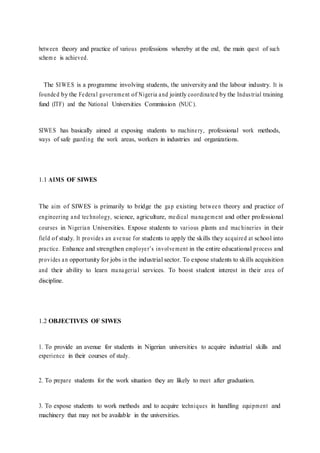
There are many different kinds of cements. In concrete, the most commonly used is
Portland cement, hydraulic cement which sets and hardens by chemical reaction with water
and is capable of doing so under water. Cement is the “glue” that binds the concrete
ingredients together and is instrumental for the strength of the composite. Although cements
and concrete have beenaround for thousands of years, modern Portland cement was invented
in 1824 by Joseph Aspdin of Leeds, England. The name derives from its resemblance of the
natural building stone quarried in Portland, England.
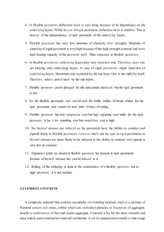
Fig 3.1- Portland cement
ii. Aggregate
The aggregate is a granular material, such as sand, gravel, crushed stone, or iron-blast furnace
slag. It is graded by passing it through a set of sieves with progressively smaller mesh sizes.
All material that passes through sieve #4 [0.187 in. (4.75 mm) openings] is conventionally](https://image.slidesharecdn.com/itreportc1-220822031324-e1017ca1/85/ITREPORTC-1-docx-72-320.jpg)


![reaction, often after years of seemingly satisfactory service. Other common causes of chemical
attack are sulphates found in soils, chlorides in seawater, acid rain, and other industrial
pollutants.
Generally, structures built with well-designed concrete mixes, having low porosity or high
density and minimal cracking, are likely to resist most causes of chemical attack, although for
service in particularly aggressive environments special countermeasures may have to be taken.
Under repeated load applications, structures can experience fatigue failure, as each successive
load cycle increases the degree of cracking and material deterioration to the point where the
material itself may gradually lose its strength or the increased extent of cracking is the source
of loss of durability.
Thermal and other properties
The heavy weight of concrete [its specific gravity is typically 2.4 g/cm3 (145 lb/ft3)] is the
source of large thermal mass. For this reason, massive concrete walls and roof and floor slabs
are well suited for storing thermal energy. Because of this heat capacity of concrete, together
with its reasonably low thermal conductivity, concrete structures can moderate extreme
temperature cycles and increase the comfort of occupants. Well designed concrete mixes are
impermeable to liquids and therefore suitable for storage tanks without the need for
impermeable membranes or liners. Although steel reinforcing bars conduct electricity and
influence magnetic fields, the concrete itself does neither.
Batching of Concrete:
Batching is the process of measuring concrete mix ingredients by either mass or volume and
introducing them into the mixer. To produce concrete of uniform quality, the ingredients must
be measured accurately for each batch. Most specifications require that batching be done by
mass rather than by volume (ASTM C 94 or AASHTO M 157). Water and liquid admixtures
can be measured accurately by either volume or mass. Volumetric batching (ASTM C 685 or
AASHT O M 241) is used for concrete mixed in continuous mixers. Specifications generally
require that materials be measured for individual batches within the following percentages of
accuracy: cementation material: l% aggregates: 2%, water: l%, and admixtures: 3%.
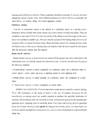
Mixing of concrete:
All concrete should be mixed thoroughly until it is uniform in appearance, with all ingredients
evenly distributed. Mixers should not be loaded above their rated capacities and should be
operated at the mixing speed recommended by the manufacturer. Increased output should be
obtained by using a larger mixer or additional mixes, rather than byspeeding up or overloading](https://image.slidesharecdn.com/itreportc1-220822031324-e1017ca1/85/ITREPORTC-1-docx-82-320.jpg)