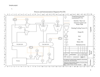
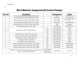
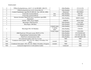
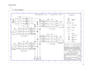
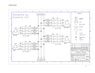
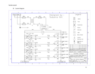
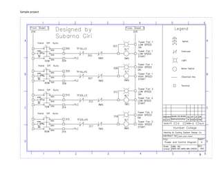
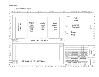
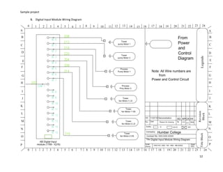
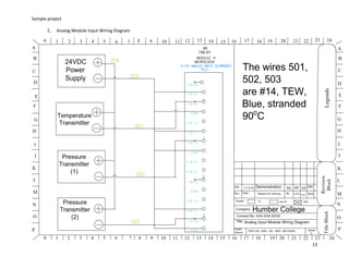
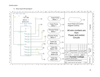
Sample project
1
A sample Project (control Design)
Overview
Prepare engineering design schematic drawings and documentation to control the temperature and pressure of a Water Cooling
System. The drawings have to be completed using AutoCAD to engineering design standards.
The Water Cooling System has two (2) hydraulic water Runs: Hot Water Run and Cool Water Run. The Hot Water Run is for hot
water and the Cool Water Run is for cool water. Each Run has a tank.
A PLC is used to control the Water Cooling System.
In the Hot Water Run, hot water is pumped from the Hot Water Tank by two (2) Tower Pumps (one for each Cooling Tower). The hot
water is then cooled in the two (2) Cooling Towers. Each Cooling Tower has a fan which can be used to cool the water even more as it
is sprayed down the Cooling Tower. Each fan can be run at a high or a low speed to get the required cooling. The water thus cooled
then flows back to the Cool Water Tank by gravity.
In the Cool Water Run, two (2) Process Pumps take cool water from the Cool Water Tank and pump it to the Process. The Process
heats the water and the heated water is then returned to the Hot Water Tank by gravity.
The temperature of the cool water in the Cool Water Tank is monitored by the PLC.
The pressure of the water going to the Process is also monitored by the PLC.
The PLC is programmed to Stop and Start the pumps and fans to maintain the water at the desired temperature and pressure.
The PLC is to be located inside the electrical control panel together with the motor starters, fuses and other associated hardware.
The operator will be able to monitor the Process via an HMI located on the door of the electrical control panel.
Each pump and fan motor will have its own selector switch so that the operator can manually control each pump and fan separately.
Motor Specifications
Supply voltage: 3 phase, 460 Volts, 60 Hz.
All motors are started across the line using Magnetic Motor Starters.
All motors run at the supply voltage.
Tower Pump motors: WEG, Three Phase General Purpose, ODP, Foot Mount, NEMA 254T Frame, 15hp at 1800 rpm
Sample project
2
Tower Fan motors: WEG, TEFC general purpose, Cooling Tower Motor, Double Speed, NEMA 254T Frame, High Efficiency, 3.75hp at
900 rpm / 15hp at 1800 rpm.
Process Pump motors: WEG, Three Phase general purpose, ODP, Foot Mount, NEMA 286T Frame, 30hp at 1800 rpm
Transmitter Specifications
Temperature Transducer, Cool Water Tank: 0-100o
C, RTD 4-20 mA
Pressure Transducer, Process Pump 1: 0-100 psi 4-20 mA
Pressure Transducer, Process Pump 2: 0-100 psi 4-20 mA
Table of Content
1. P & ID Diagram
2. Bill of material (BOM)
3. Power and Control Wiring Diagram
4. PLC & HMI Wiring Diagram
5. Control Panel Arrangement
6. Ladder Logic PLC Program (Using RSLogix5000, RSLogix500, PLC-5 or Omron)
7. HMI Program (using PanelBuilder32, CX Designer, PV+
software)
8. Control remotely using either Serial or Ethernet connection with LAN or WAN directly to a PC collaborating with
FactoryTalk View Studio software.
Sample project
3
1.
Sample project
4
2.
Bill of Material: Assignment #2 (Control Design)
Qty/Tag Description manufacturer Model
1 Electrical Panel Rittal Freestanding,NEMA 4 rated Rittal TSFM636312NC
2 Tower Pump Motor (TPM), 15hp, 460VAC, 60Hz WEG Motor 01518OT3E254T
2 Tower Fan Motor (TFM), 15/3.75hp, 460VAC, 60Hz WEG Motor
01589EP3QCT254VF1-
W2
2 Process Pump Motor (PPM), 30hp, 460VAC, 60Hz WEG Motor 03018OT3E286T
1 Disconnect Switch, TYPE OES ,3-poles, 460V,200A ABB OS200J03
1 Power Distribution Block, 460V,3-poles Allen Bradley 1492-PD31123
6
Motor Fuses, TYPE J, Time delay Fuses
9A Farraz Shawmut AJT9
12 25A Farraz Shawmut AJT25
6 45A Farraz Shawmut AJT45
2 Transformer Fuses, TYPE J, Time delay Fuses 1.6A Farraz Shawmut AJT1-6/10
1 Transformer Fuses, TYPE J, Time delay Fuses 8A Farraz Shawmut AJT8
2 Fuse Holders, TYPE J, Transformers Fuses 30A Farraz Shawmut US3J1I
6 Fuse Holder, TYPE J, motors,Fuses 30A Farraz Shawmut US3J3I
2 Fuse Holder, TYPE J, motors,Fuses 60A Farraz Shawmut US6J3I
2 Contactor, Motor and Fan, TYPE 100-C, IEC, 24VDC 9A Allen Bradley 100-C09UEJ10
4 Contactor, Motor and Fan, TYPE 100-C, IEC, 24VDC 23A Allen Bradley 100-C23EJ01
2 Contactor, Motor and Fan, TYPE 100-C, IEC, 24VDC 43A Allen Bradley 100-C43EJ10
4
TPM/TFM↑ -Overload devices,IEC, manual reset, adjustment range
(A) 12…32, for 100-C09..100-C23
IEC, Manual
Reset for 3Φ
Applications
Allen Bradley 193-EA4GB
Sample project
5
2 TFM↓-Overload devices,..(A)3.7..12, for100-M05..100-C23 Allen Bradley 193-EA1FB
2 PPM-Overload devices (A)14..45,for100-C43 Allen Bradley 193-EA4JD
1 Control Transformer, type PH, Pri 460VAC, Sec 120VAC, 60Hz Hammond PH150MLI
3 Touch Safe Terminal Blocks 24A Allen Bradley 1492-W3
1 Touch Safe Terminal Blocks 41A Allen Bradley 1492-W6
8
Selector Switches, Hand-Off-Auto (3 position), type-800F,
Illuminated
Allen Bradley 800FP-LSM33
1 24VDC 120W, Power Supply OMRON S8VS-12024
1 Micrologix 1500 Processor Allen Bradley 1764-LRP
1 Micrologix 1500 Base Allen Bradley 1764-24BWA
1 Micrologix PLC I/O Modules
8-digital input Allen Bradley 1769-IQ16
3- analog
input
Allen Bradley 1769-IF4
8-relay output Allen Bradley 1769-OW8
1 HMI Panelview 550 touch screen, RS232, 0.75A Allen Bradley 2711P-B10C4A8
1 Programming Communication Cable Allen Bradley 1747-PIC SLC500
1 PanelView communication Cable Allen Bradley IJ85J-M8TBJM-1M9
19 I/O connection probes with #14, Cu-wire TBD TBD
TBD
Conductor with-in panel - #0/2, #8, #14 - Black, #14-white, #14-
green
stranded TBD TWE
TBD Conductor from panel - #0/2, #8, #14 - Black, #14-white, #14-green stranded TBD T90
TBD Lamacoid (engraved on 2-color plastic) Labels Lamacoid TBD
Sample project
6
3.
A. Power Diagram
Sample project
7
Sample project
8
B. Control Diagram
Sample project
9
Sample project
10
4.
Wire no. # Size Description Wire no. # Size Description Wire no. # Size Description
a 000 TEW, Black,90c 128 14 TEW, Black 90C 209 14 TEW, Blue 90 C
b 000 TEW, Black,90c 129 14 TEW, Black 90C 210 14 TEW, Blue 90 C
c 000 TEW, Black,90c 130 14 T90, Black 90 C 211 14 TEW, Blue 90 C
100 000 T90, Black,90c 131 14 T90, Black 90 C 212 14 TEW, Blue 90 C
101 000 T90, Black,90c 132 14 T90, Black 90 C 213 14 TEW, Blue 90 C
102 000 T90, Black,90c 133 14 TEW, Black,90c 214 14 TEW, Blue 90 C
103 14 TEW, Black,90c 134 14 TEW, Black,90c 215 14 TEW, Blue 90 C
104 14 TEW, Black 90 C 135 14 TEW, Black,90c 216 14 TEW, Blue 90 C
105 14 TEW, Black 90 C 136 14 T90, Black 90 C 217 14 TEW, Blue 90 C
106 14 T90, Black 90 C 137 14 T90, Black 90 C 218 14 TEW, Blue 90 C
107 14 T90, Black 90 C 138 14 T90, Black 90 C 219 14 TEW, Blue 90 C
108 14 T90, Black 90 C 139 8 TEW, Black 90 C 220 14 TEW, Blue 90 C
109 14 TEW, Black 90 C 140 8 TEW, Black,90c 221 14 TEW, Blue 90 C
110 14 TEW, Black 90 C 141 8 TEW, Black,90c 300 14 TEW, Blue 90 C
111 14 TEW, Black 90 C 142 8 T90, Black 90 C 301 14 TEW, Blue 90 C
112 14 T90, Black 90 C 143 8 T90, Black 90 C 302 14 TEW, Blue 90 C
113 14 T90, Black 90 C 144 8 T90, Black 90 C 303 14 TEW, Blue 90 C
114 14 T90, Black 90 C 145 8 TEW, Black,90c 304 14 TEW, Blue 90 C
115 14 TEW, Black 90C 146 8 TEW, Black,90c 305 14 TEW, Blue 90 C
116 14 TEW, Black 90C 147 8 TEW, Black,90c 306 14 TEW, Blue 90 C
117 14 TEW, Black 90C 148 8 T90, Black 90 C 307 14 TEW, Blue 90 C
118 14 T90, Black 90 C 149 8 T90, Black 90 C 308 14 TEW, Blue 90 C
119 14 T90, Black 90 C 150 8 T90, Black 90 C 309 14 TEW, Blue 90 C
120 14 T90, Black 90 C GND 8 T90, Green 90 C 310 14 TEW, Blue 90 C
121 14 TEW, Black 90C 200 14 TEW, Black 90 C 311 14 TEW, Blue 90 C
122 14 TEW, Black 90C 201 14 TEW, Black 90 C 312 14 TEW, Blue 90 C
123 14 TEW, Black 90C 202 14 TEW, Black 90 C 313 14 TEW, Blue 90 C
124 14 T90, Black 90 C 203 14 TEW, Black 90 C 314 14 TEW, Blue 90 C
125 14 T90, Black 90 C 204 14 TEW, Blue 90 C 315 14 TEW, Blue 90 C
126 14 T90, Black 90 C 205 14 TEW, Blue 90 C 316 14 TEW, Blue 90 C
127 14 TEW, Black 90C 206 14 TEW, Blue 90 C 317 14 TEW, Blue 90 C
400 000 TEW, Black, 90c 207 14 TEW, Blue 90 C 318 14 TEW, Blue 90 C
401 000 TEW, Black, 90c 208 14 TEW, Blue 90 C 319 14 TEW, Blue 90 C
402 000 TEW, Black, 90c N 14 T90, White 90C
4. Wire
Specification
Table
Note: All wires
are stranded
Sample project
11
A. PLC and HMI Block Diagram
Sample project
12
B. Digital Input Module Wiring Diagram
Sample project
13
C. Analog Module Input Wiring Diagram
Sample project
14
D. Relay output Wiring Diagram
Sample project
15
5. Panel layouts
A.
Sample project
16
B.
Sample project
17
C.
Sample project
18
D.
Sample project
19
6. PLC Ladder Logix

A sample Control Design Project

  • 1.
    Sample project 1 A sampleProject (control Design) Overview Prepare engineering design schematic drawings and documentation to control the temperature and pressure of a Water Cooling System. The drawings have to be completed using AutoCAD to engineering design standards. The Water Cooling System has two (2) hydraulic water Runs: Hot Water Run and Cool Water Run. The Hot Water Run is for hot water and the Cool Water Run is for cool water. Each Run has a tank. A PLC is used to control the Water Cooling System. In the Hot Water Run, hot water is pumped from the Hot Water Tank by two (2) Tower Pumps (one for each Cooling Tower). The hot water is then cooled in the two (2) Cooling Towers. Each Cooling Tower has a fan which can be used to cool the water even more as it is sprayed down the Cooling Tower. Each fan can be run at a high or a low speed to get the required cooling. The water thus cooled then flows back to the Cool Water Tank by gravity. In the Cool Water Run, two (2) Process Pumps take cool water from the Cool Water Tank and pump it to the Process. The Process heats the water and the heated water is then returned to the Hot Water Tank by gravity. The temperature of the cool water in the Cool Water Tank is monitored by the PLC. The pressure of the water going to the Process is also monitored by the PLC. The PLC is programmed to Stop and Start the pumps and fans to maintain the water at the desired temperature and pressure. The PLC is to be located inside the electrical control panel together with the motor starters, fuses and other associated hardware. The operator will be able to monitor the Process via an HMI located on the door of the electrical control panel. Each pump and fan motor will have its own selector switch so that the operator can manually control each pump and fan separately. Motor Specifications Supply voltage: 3 phase, 460 Volts, 60 Hz. All motors are started across the line using Magnetic Motor Starters. All motors run at the supply voltage. Tower Pump motors: WEG, Three Phase General Purpose, ODP, Foot Mount, NEMA 254T Frame, 15hp at 1800 rpm
  • 2.
    Sample project 2 Tower Fanmotors: WEG, TEFC general purpose, Cooling Tower Motor, Double Speed, NEMA 254T Frame, High Efficiency, 3.75hp at 900 rpm / 15hp at 1800 rpm. Process Pump motors: WEG, Three Phase general purpose, ODP, Foot Mount, NEMA 286T Frame, 30hp at 1800 rpm Transmitter Specifications Temperature Transducer, Cool Water Tank: 0-100o C, RTD 4-20 mA Pressure Transducer, Process Pump 1: 0-100 psi 4-20 mA Pressure Transducer, Process Pump 2: 0-100 psi 4-20 mA Table of Content 1. P & ID Diagram 2. Bill of material (BOM) 3. Power and Control Wiring Diagram 4. PLC & HMI Wiring Diagram 5. Control Panel Arrangement 6. Ladder Logic PLC Program (Using RSLogix5000, RSLogix500, PLC-5 or Omron) 7. HMI Program (using PanelBuilder32, CX Designer, PV+ software) 8. Control remotely using either Serial or Ethernet connection with LAN or WAN directly to a PC collaborating with FactoryTalk View Studio software.
  • 3.
  • 4.
    Sample project 4 2. Bill ofMaterial: Assignment #2 (Control Design) Qty/Tag Description manufacturer Model 1 Electrical Panel Rittal Freestanding,NEMA 4 rated Rittal TSFM636312NC 2 Tower Pump Motor (TPM), 15hp, 460VAC, 60Hz WEG Motor 01518OT3E254T 2 Tower Fan Motor (TFM), 15/3.75hp, 460VAC, 60Hz WEG Motor 01589EP3QCT254VF1- W2 2 Process Pump Motor (PPM), 30hp, 460VAC, 60Hz WEG Motor 03018OT3E286T 1 Disconnect Switch, TYPE OES ,3-poles, 460V,200A ABB OS200J03 1 Power Distribution Block, 460V,3-poles Allen Bradley 1492-PD31123 6 Motor Fuses, TYPE J, Time delay Fuses 9A Farraz Shawmut AJT9 12 25A Farraz Shawmut AJT25 6 45A Farraz Shawmut AJT45 2 Transformer Fuses, TYPE J, Time delay Fuses 1.6A Farraz Shawmut AJT1-6/10 1 Transformer Fuses, TYPE J, Time delay Fuses 8A Farraz Shawmut AJT8 2 Fuse Holders, TYPE J, Transformers Fuses 30A Farraz Shawmut US3J1I 6 Fuse Holder, TYPE J, motors,Fuses 30A Farraz Shawmut US3J3I 2 Fuse Holder, TYPE J, motors,Fuses 60A Farraz Shawmut US6J3I 2 Contactor, Motor and Fan, TYPE 100-C, IEC, 24VDC 9A Allen Bradley 100-C09UEJ10 4 Contactor, Motor and Fan, TYPE 100-C, IEC, 24VDC 23A Allen Bradley 100-C23EJ01 2 Contactor, Motor and Fan, TYPE 100-C, IEC, 24VDC 43A Allen Bradley 100-C43EJ10 4 TPM/TFM↑ -Overload devices,IEC, manual reset, adjustment range (A) 12…32, for 100-C09..100-C23 IEC, Manual Reset for 3Φ Applications Allen Bradley 193-EA4GB
  • 5.
    Sample project 5 2 TFM↓-Overloaddevices,..(A)3.7..12, for100-M05..100-C23 Allen Bradley 193-EA1FB 2 PPM-Overload devices (A)14..45,for100-C43 Allen Bradley 193-EA4JD 1 Control Transformer, type PH, Pri 460VAC, Sec 120VAC, 60Hz Hammond PH150MLI 3 Touch Safe Terminal Blocks 24A Allen Bradley 1492-W3 1 Touch Safe Terminal Blocks 41A Allen Bradley 1492-W6 8 Selector Switches, Hand-Off-Auto (3 position), type-800F, Illuminated Allen Bradley 800FP-LSM33 1 24VDC 120W, Power Supply OMRON S8VS-12024 1 Micrologix 1500 Processor Allen Bradley 1764-LRP 1 Micrologix 1500 Base Allen Bradley 1764-24BWA 1 Micrologix PLC I/O Modules 8-digital input Allen Bradley 1769-IQ16 3- analog input Allen Bradley 1769-IF4 8-relay output Allen Bradley 1769-OW8 1 HMI Panelview 550 touch screen, RS232, 0.75A Allen Bradley 2711P-B10C4A8 1 Programming Communication Cable Allen Bradley 1747-PIC SLC500 1 PanelView communication Cable Allen Bradley IJ85J-M8TBJM-1M9 19 I/O connection probes with #14, Cu-wire TBD TBD TBD Conductor with-in panel - #0/2, #8, #14 - Black, #14-white, #14- green stranded TBD TWE TBD Conductor from panel - #0/2, #8, #14 - Black, #14-white, #14-green stranded TBD T90 TBD Lamacoid (engraved on 2-color plastic) Labels Lamacoid TBD
  • 6.
  • 7.
  • 8.
  • 9.
  • 10.
    Sample project 10 4. Wire no.# Size Description Wire no. # Size Description Wire no. # Size Description a 000 TEW, Black,90c 128 14 TEW, Black 90C 209 14 TEW, Blue 90 C b 000 TEW, Black,90c 129 14 TEW, Black 90C 210 14 TEW, Blue 90 C c 000 TEW, Black,90c 130 14 T90, Black 90 C 211 14 TEW, Blue 90 C 100 000 T90, Black,90c 131 14 T90, Black 90 C 212 14 TEW, Blue 90 C 101 000 T90, Black,90c 132 14 T90, Black 90 C 213 14 TEW, Blue 90 C 102 000 T90, Black,90c 133 14 TEW, Black,90c 214 14 TEW, Blue 90 C 103 14 TEW, Black,90c 134 14 TEW, Black,90c 215 14 TEW, Blue 90 C 104 14 TEW, Black 90 C 135 14 TEW, Black,90c 216 14 TEW, Blue 90 C 105 14 TEW, Black 90 C 136 14 T90, Black 90 C 217 14 TEW, Blue 90 C 106 14 T90, Black 90 C 137 14 T90, Black 90 C 218 14 TEW, Blue 90 C 107 14 T90, Black 90 C 138 14 T90, Black 90 C 219 14 TEW, Blue 90 C 108 14 T90, Black 90 C 139 8 TEW, Black 90 C 220 14 TEW, Blue 90 C 109 14 TEW, Black 90 C 140 8 TEW, Black,90c 221 14 TEW, Blue 90 C 110 14 TEW, Black 90 C 141 8 TEW, Black,90c 300 14 TEW, Blue 90 C 111 14 TEW, Black 90 C 142 8 T90, Black 90 C 301 14 TEW, Blue 90 C 112 14 T90, Black 90 C 143 8 T90, Black 90 C 302 14 TEW, Blue 90 C 113 14 T90, Black 90 C 144 8 T90, Black 90 C 303 14 TEW, Blue 90 C 114 14 T90, Black 90 C 145 8 TEW, Black,90c 304 14 TEW, Blue 90 C 115 14 TEW, Black 90C 146 8 TEW, Black,90c 305 14 TEW, Blue 90 C 116 14 TEW, Black 90C 147 8 TEW, Black,90c 306 14 TEW, Blue 90 C 117 14 TEW, Black 90C 148 8 T90, Black 90 C 307 14 TEW, Blue 90 C 118 14 T90, Black 90 C 149 8 T90, Black 90 C 308 14 TEW, Blue 90 C 119 14 T90, Black 90 C 150 8 T90, Black 90 C 309 14 TEW, Blue 90 C 120 14 T90, Black 90 C GND 8 T90, Green 90 C 310 14 TEW, Blue 90 C 121 14 TEW, Black 90C 200 14 TEW, Black 90 C 311 14 TEW, Blue 90 C 122 14 TEW, Black 90C 201 14 TEW, Black 90 C 312 14 TEW, Blue 90 C 123 14 TEW, Black 90C 202 14 TEW, Black 90 C 313 14 TEW, Blue 90 C 124 14 T90, Black 90 C 203 14 TEW, Black 90 C 314 14 TEW, Blue 90 C 125 14 T90, Black 90 C 204 14 TEW, Blue 90 C 315 14 TEW, Blue 90 C 126 14 T90, Black 90 C 205 14 TEW, Blue 90 C 316 14 TEW, Blue 90 C 127 14 TEW, Black 90C 206 14 TEW, Blue 90 C 317 14 TEW, Blue 90 C 400 000 TEW, Black, 90c 207 14 TEW, Blue 90 C 318 14 TEW, Blue 90 C 401 000 TEW, Black, 90c 208 14 TEW, Blue 90 C 319 14 TEW, Blue 90 C 402 000 TEW, Black, 90c N 14 T90, White 90C 4. Wire Specification Table Note: All wires are stranded
  • 11.
    Sample project 11 A. PLCand HMI Block Diagram
  • 12.
    Sample project 12 B. DigitalInput Module Wiring Diagram
  • 13.
    Sample project 13 C. AnalogModule Input Wiring Diagram
  • 14.
    Sample project 14 D. Relayoutput Wiring Diagram
  • 15.
  • 16.
  • 17.
  • 18.
  • 19.