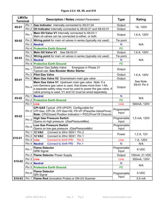
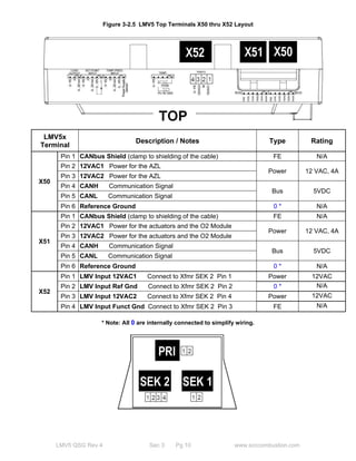
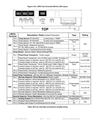
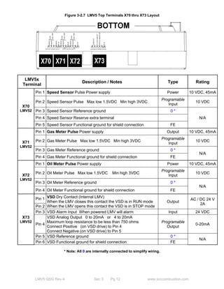
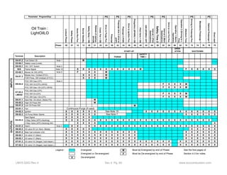
This document provides an overview and specifications for the Siemens LMV5 Burner Management System. It describes the base unit options, display options, actuator options, flame detector options and accessories, temperature and pressure sensor options, oxygen trim accessories, variable speed drive accessories, and general accessories. It also provides examples of typical BMS systems that would include components like the basic unit, display, actuators, flame scanner, temperature/pressure sensors, and transformers.
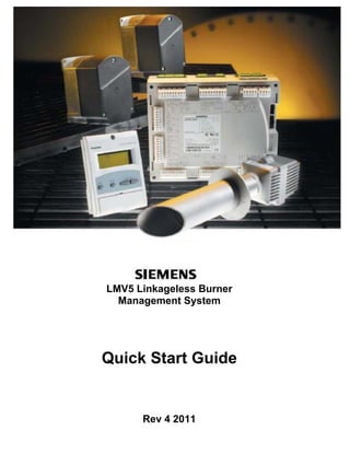

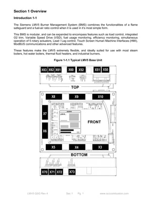
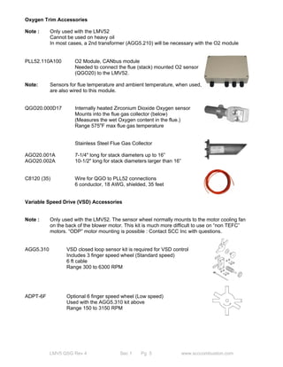


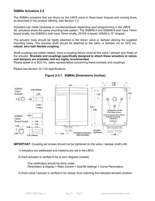


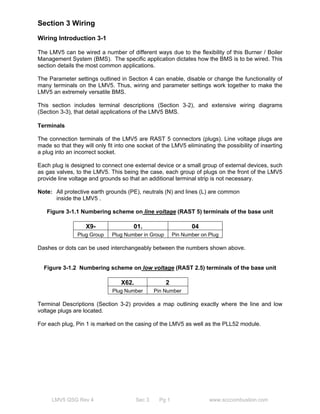
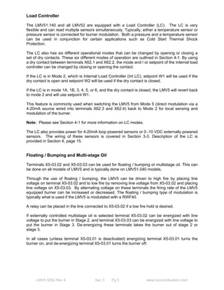


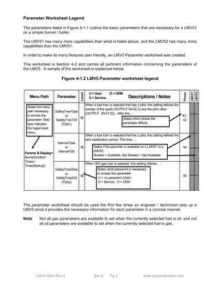
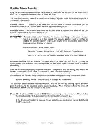
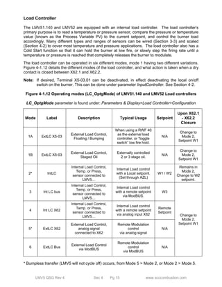


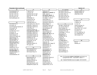
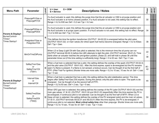
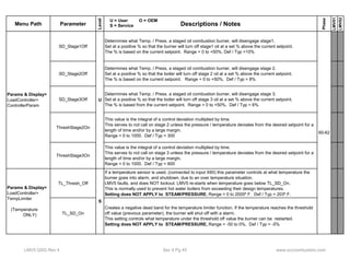
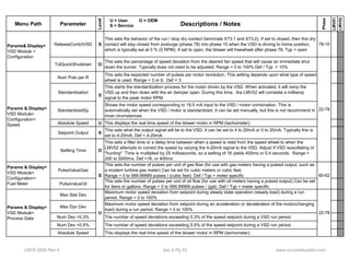

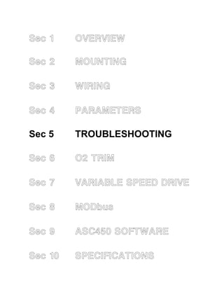
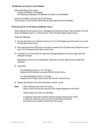
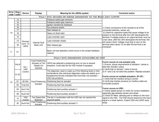
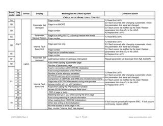
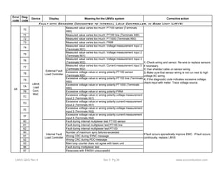
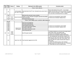

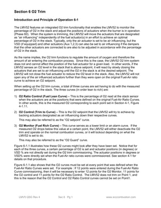
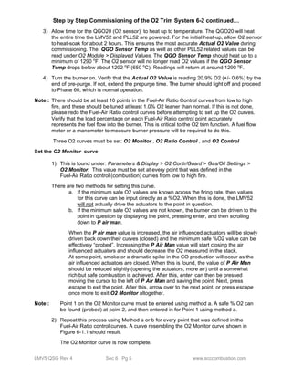
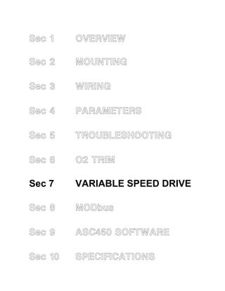

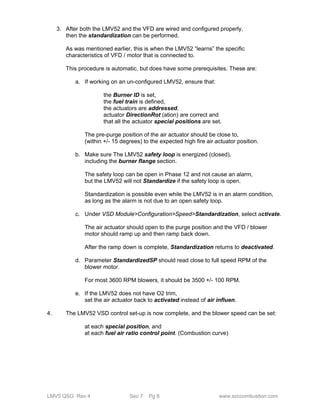

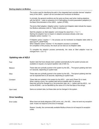
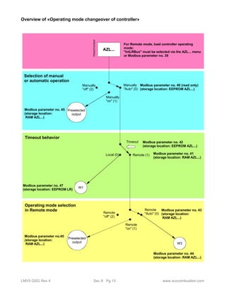
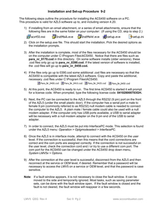
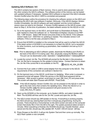
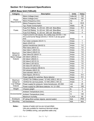
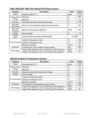
![Mapping words
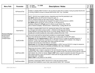
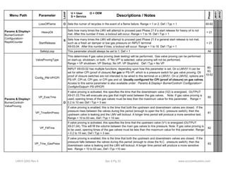
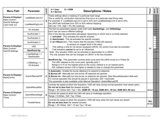
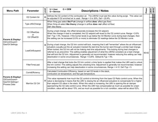
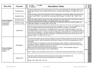
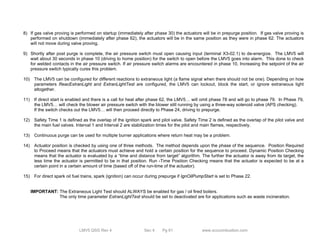
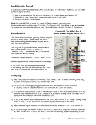
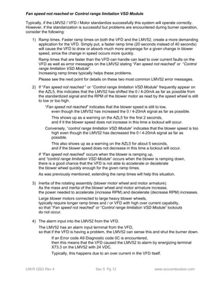
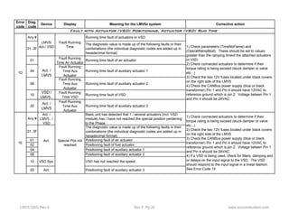
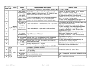
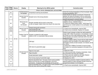
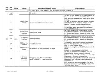
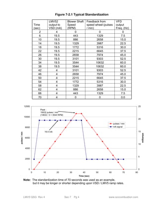
B0 B1 B2 B3 B4 B5 B6 B7 B8 B9 B10 B11 B12 B13 B14 B15
Byte High Byte Low
Transmission mode: The LSB (least significant bit) is transmitted first.
Mapping long values
Byte High Byte Low Byte High Byte Low
Word Low Word High
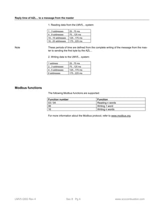
Communication process
Start and end of a data block are characterized by transmission pauses. The maximum
permissible time between 2 successive characters is 3.5 times the time required for the
transmission of once character.
The character transmission time is dependent on the Baud rate and the data format used.
Having a data format of 8 data bits, no parity bit and one stop, the character transmission
time is calculated as follows:
Character transmission time [ms] = 1000 * 9 bits / Baud rate
And with other data formats:
Character transmission time [ms] = 1000 * 10 bits / Baud rate
Data query from the master
Transmission time = n characters * 1000 * x bits / Baud rate
Marking for end of data query
3.5 characters * 1000 * x bits / Baud rate
Data query handling by the slave
Reply of slave
Transmission time = n characters * 1000 * x bits / Baud rate
Marking for end of reply
3.5 characters * 1000 * x bits / Baud rate
Marking for data query or end of reply with data format 10 / 9 bits
Waiting time = 3.5 characters * 1000 * x bits / Baud rate
Baud rate [Baud] Data format [bit] Waiting time [ms]
9600 10 3.125
9 2.813
Process
Example
LMV5 QSG Rev 4 Sec 8 Pg 2 www.scccombustion.com](https://image.slidesharecdn.com/lmv5-quickstartguide-141111081345-conversion-gate02/85/Lmv5-quickstartguide-196-320.jpg)
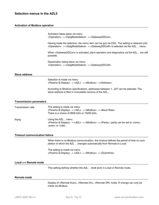
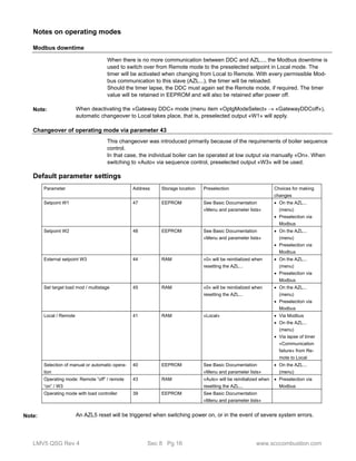
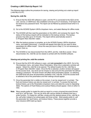
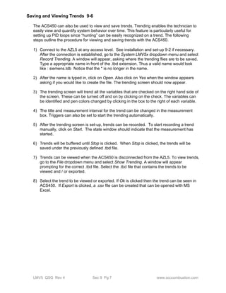
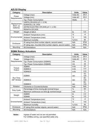
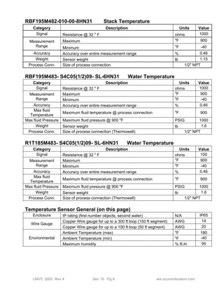
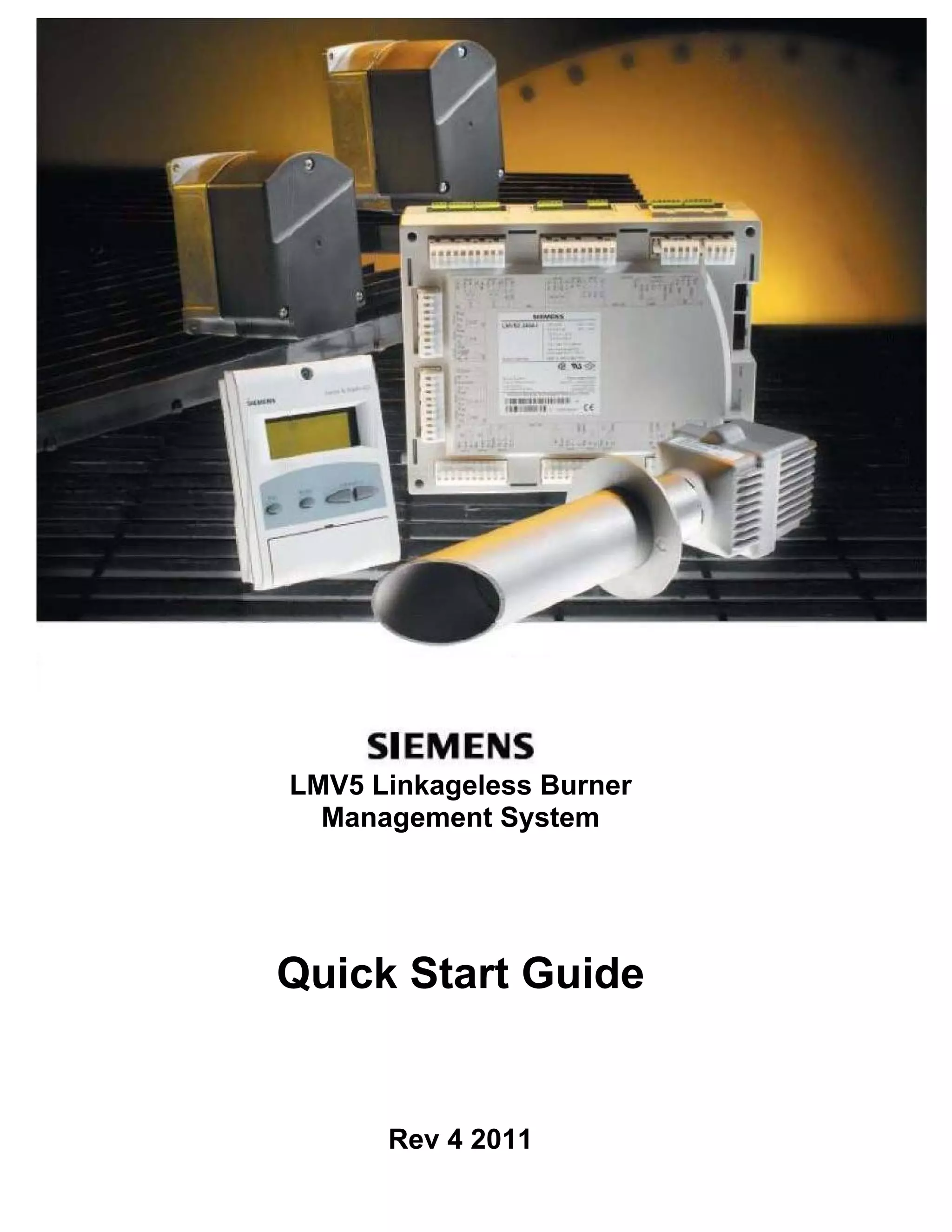
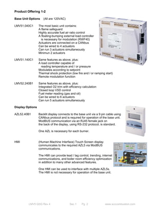
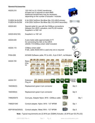
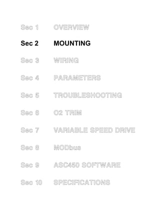
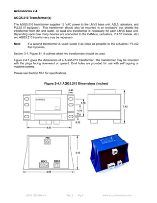
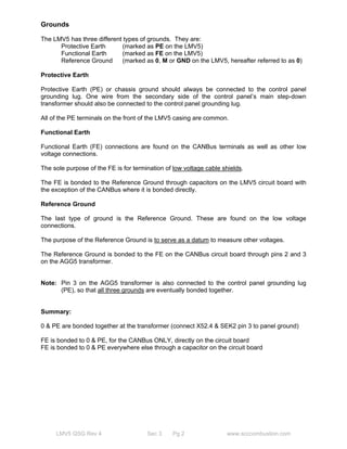
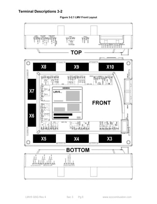
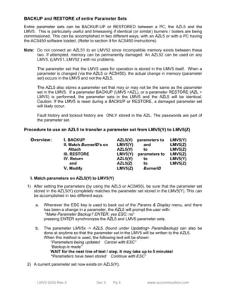
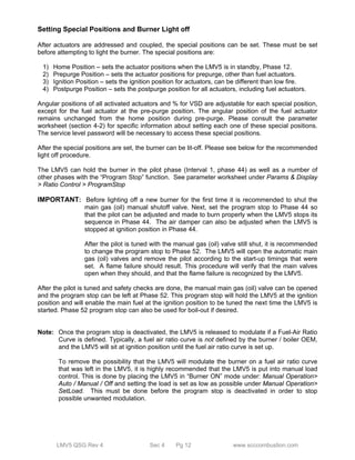
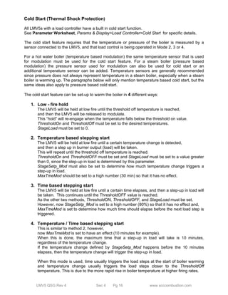
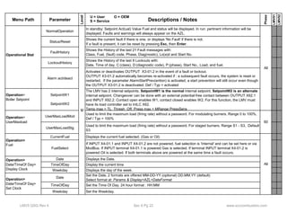
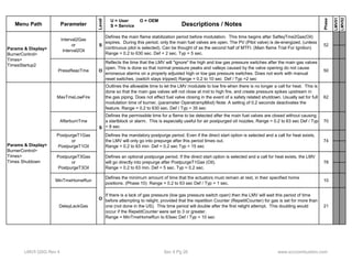
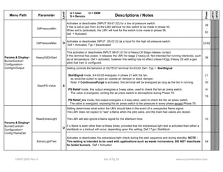
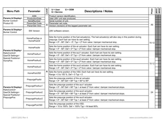
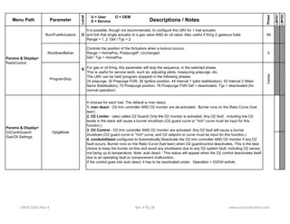
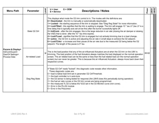
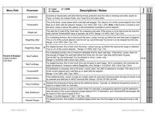
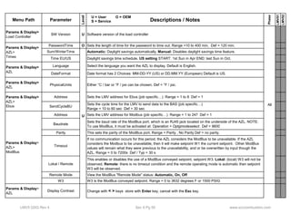
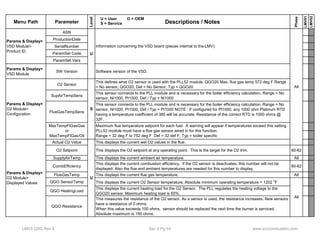
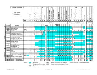
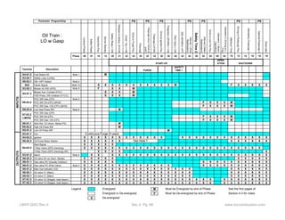
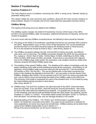
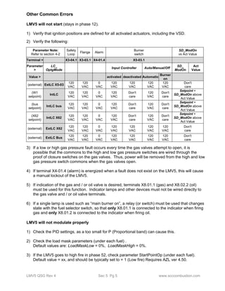
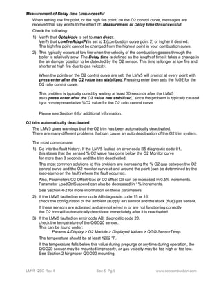
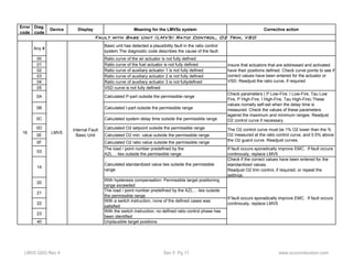
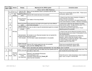
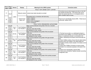
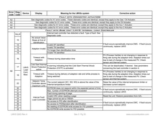
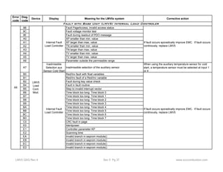
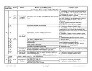
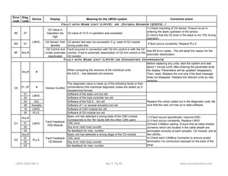
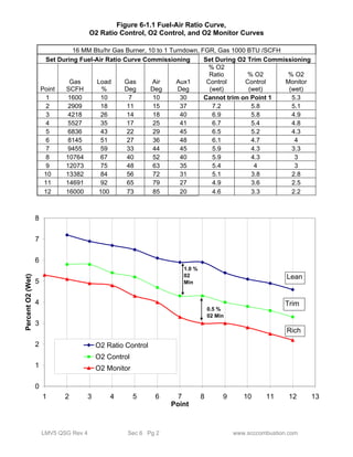
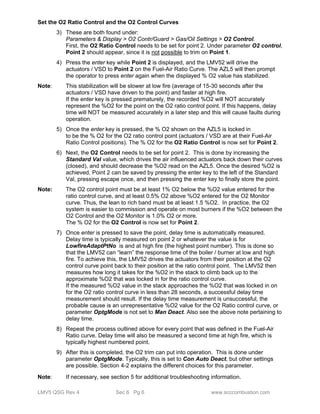
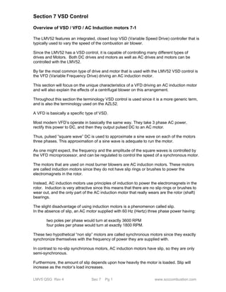
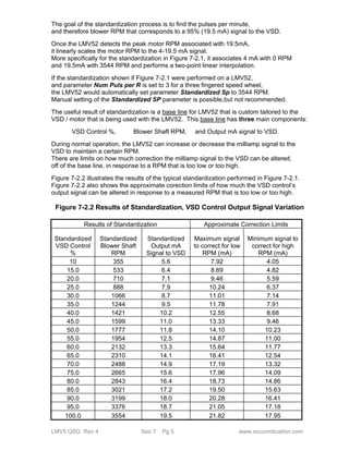
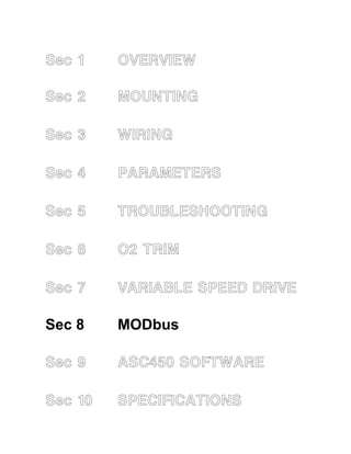
![Function Address Number
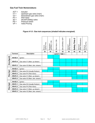
of
words
Data designation Access Data
format
Data type /
coding
Range Updating
rate
R 03/04
W 06/16
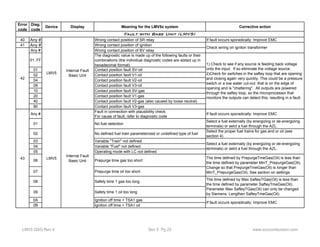
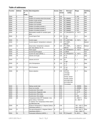
42 1 Modbus downtime:
Max. time with no communication. When this
time has elapsed, automatic changeover
from Remote to Local takes place
R/W* U16 0…7200 s Slow
R 03/04
W 06/16
43 1 Operating mode in Remote mode.
Auto, Remote ON, Remote OFF
R/W U16 0 = Auto
1 = ON
2 = OFF
0…2 Fast
R 03/04
W 06/16
44 1 External setpoint W3
Unit: See address 18 / 19
R/W U16 PT_TEMP_
DRUCK
See ”Data
types” on
page 15
Fast
R 03/04
W 06/16
45 1 Predefined output mod. / multistage R/W U16 PT_LEISTUNG See ”Data
types” on
page 15
Fast
R 03/04
W 06/16
46 1 Fuel selection AZL... R/W* U16 0 = Gas
1 = Oil
0…1 Slow
R 03/04
W 06/16
47 1 Setpoint W1 R/W U16 PT_TEMP_
DRUCK
See ”Data
types” on
page 15
Slow
R 03/04
W 06/16
48 1 Setpoint W2 R/W U16 PT_TEMP_
DRUCK
See ”Data
types” on
page 15
Slow
R 03/04
W 06/16
49 1 Weekday R/W U16 0 = Sunday
1 = Monday
...
0…6 Slow
R 03/04
W 16
50 3 Date R/W U16[3] Data structure
Date
Slow
R 03/04
W 16
53 3 Time of day R/W U16[3] Data structure
Time of day
Slow
R 03/04
W 16
56 2 Hours run gas (adjustable) R/W* S32 0...999999 h Slow
R 03/04
W 16
58 2 Hours run oil stage 1 or modulating
(adjustable)
R/W* S32 0...999999 h Slow
R 03/04
W 16
60 2 Hours run oil stage 2 or modulating
(adjustable)
R/W* S32 0...999999 h Slow
R 03/04
W 16
62 2 Hours run oil stage 3 or modulating
(adjustable)
R/W* S32 0...999999 h Slow
R 03/04
W 16
64 2 Hours run total (can be reset) R/W* S32 0...999999 h Slow
03/04 66 2 Hours run total (read only) R S32 0...999999 h Slow
03/04 68 2 Hours run device connected to power
(read only
R S32 0...999999 h Slow
R 03/04
W 16
70 2 Startup counter gas (adjustable) R/W* S32 0...999999 Slow
R 03/04
W 16
72 2 Startup counter oil (adjustable) R/W* S32 0...999999 Slow
R 03/04
W 16
74 2 Startup counter total (can be reset) R/W* S32 0...999999 Slow
03/04 76 2 Startup counter total (read only) R S32 0...999999 Slow
03/04 78 2 Fuel volume gas (read only)
(resettable from AZL5... version V4.10)
0…199999999.9 m³
0…1999999999 ft³
R/W* S32 See ”Data
types” on
page 15
Slow
LMV5 QSG Rev 4 Sec 8 Pg 7 www.scccombustion.com](https://image.slidesharecdn.com/lmv5-quickstartguide-141111081345-conversion-gate02/85/Lmv5-quickstartguide-201-320.jpg)
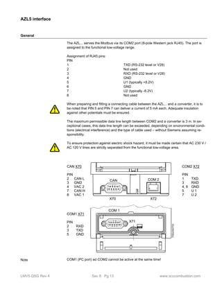
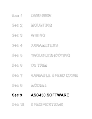
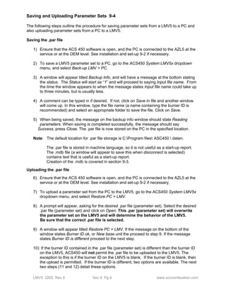
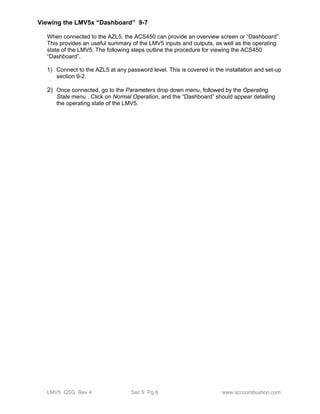
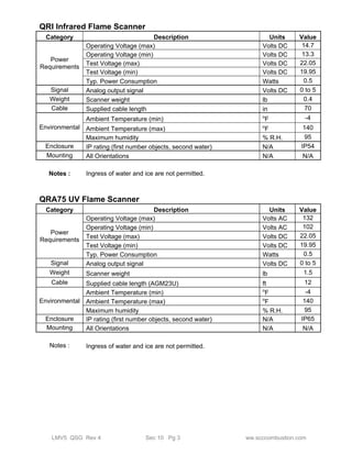
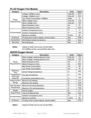
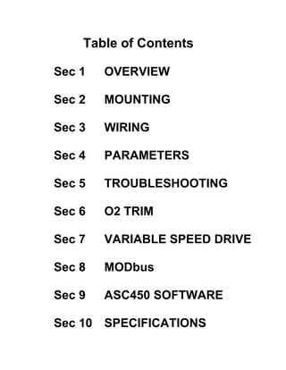
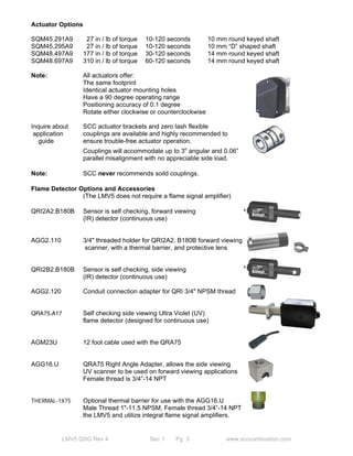
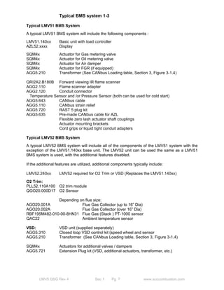
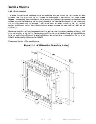
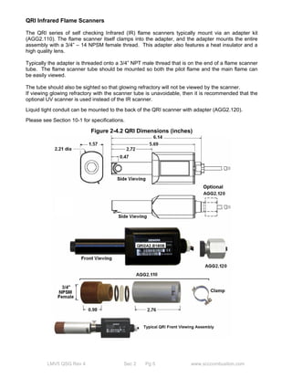
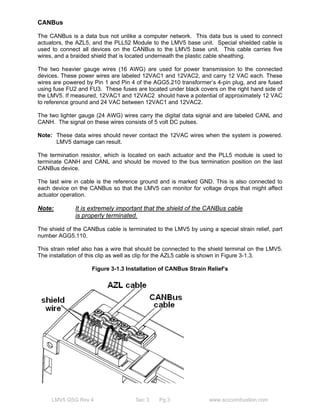
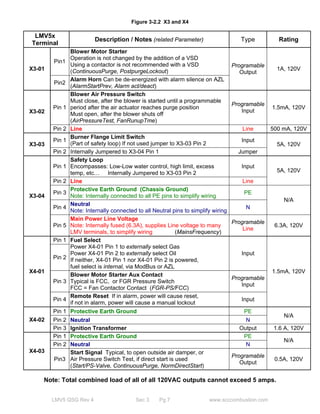
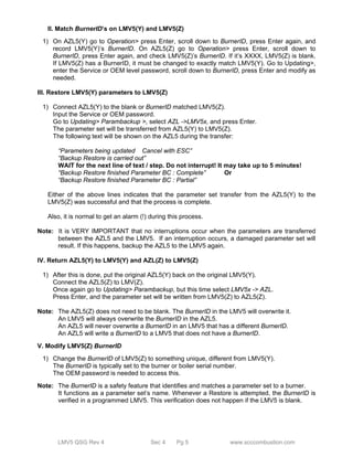
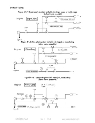
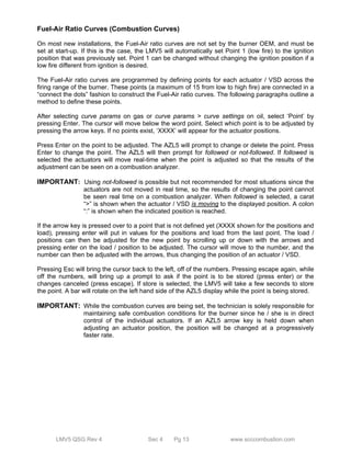
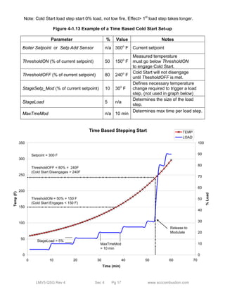
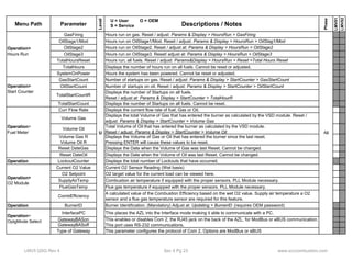
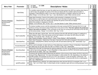
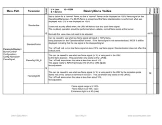
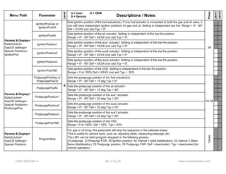
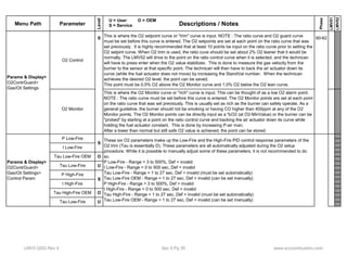
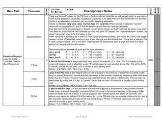
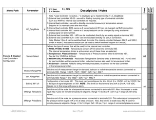
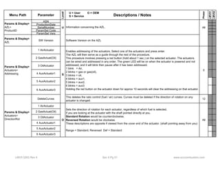
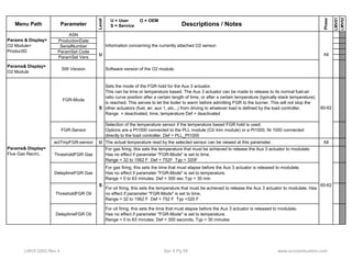
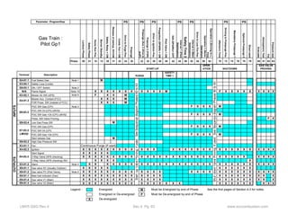
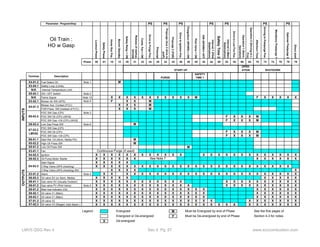
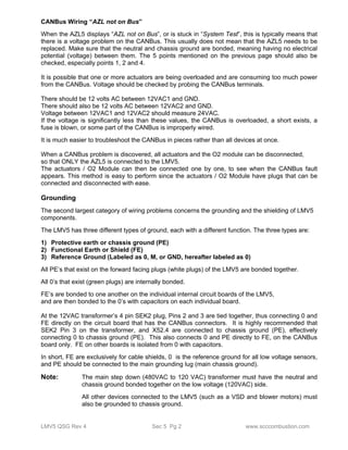
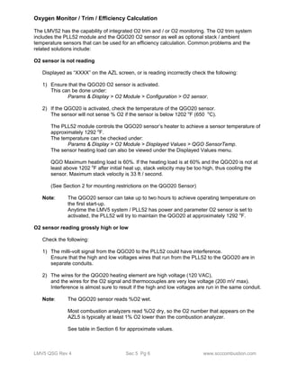
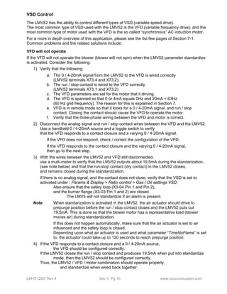
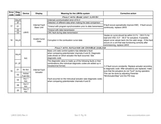
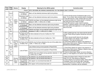
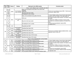
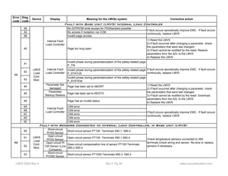
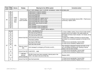
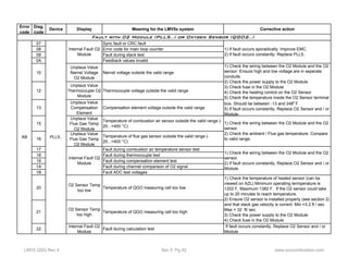
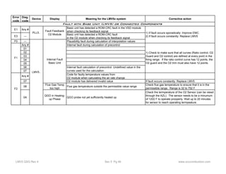
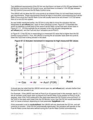
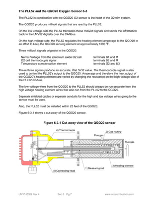
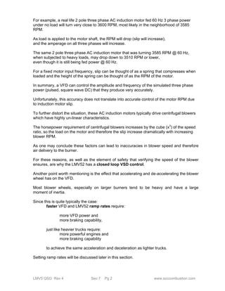
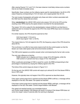
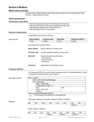
![Function Address Number
of
words
Data designation Access Data
format
Data type /
coding
Range Updating
rate
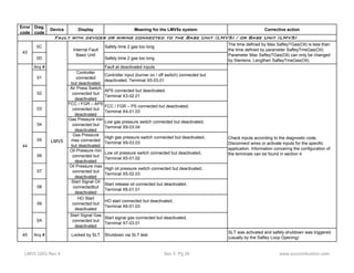
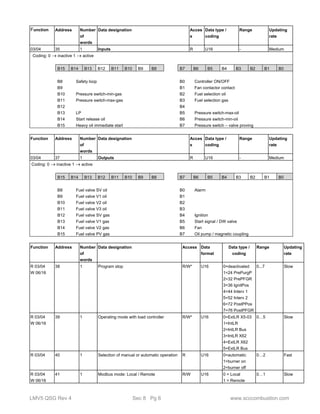
03/04 80 2 Fuel volume oil (read only)
(resettable from AZL5... version V4.10)
0…199999999.9 l
0…199999999.9 gal
R/W* S32 See ”Data
types” on
page 15
Slow
03/04 82 1 Number of lockouts R U16 0…65535 Slow
03/04 83 1 Extra temperature sensor
(from AZL5... version V4.10)
R U16 °C: *1
°F: *1
0..2000 °C
32..3632 °F
Slow
Parameters 84...137 are available from AZL5... version V4.20
03/04 84 8 AZL5... ASN R U8[16] String Constant
03/04 92 1 AZL5... parameter set code R U16 Constant
03/04 93 1 AZL5... parameter set version R U16 Constant
03/04 94 3 AZL5... identification date R U16[3] Date Constant
03/04 97 1 AZL5... identification number R U16 Constant
03/04 98 8 Burner control ASN R U8[16] String Constant
03/04 106 1 Burner control parameter set code R U16 Constant
03/04 107 1 Burner control parameter set version R U16 Constant
03/04 108 3 Burner control identification date R U16[3] Date Constant
03/04 111 1 Burner control identification number R U16 Constant
03/04 112 1 Software version AZL5... R U16 Hexadecimal Constant
03/04 113 1 Software version burner control R U16 Hexadecimal Constant
03/04 114 1 Software version load controller R U16 Hexadecimal Constant
03/04 115 8 Burner identification R U8[16] String Upon
reset
03/04 123 1 Min-output gas R U16 PT_LEISTUNG 0...100 % Slow
03/04 124 1 Max-output gas R U16 PT_LEISTUNG 0...100 % Slow
03/04 125 1 Min-output oil R U16 PT_LEISTUNG 0...100 %
1001...1003
Slow
03/04 126 1 Max-output oil R U16 PT_LEISTUNG 0...100 %
1001...1003
Slow
R 03/04
W 16
127 1 Load limitation enduser (modulating) R/W* U16 PT_LEISTUNG 0...100 % Slow
R 03/04
W 16
128 1 Load limitation enduser (multistage) R/W* U16 0: S1
1: S2
2: S3
0...2 Slow
03/04 129 1 Temperature limiter switching differential ON
(in address 29: Temperature limiter OFF
threshold, in degrees Celsius / Fahrenheit)
R S16 PT_Prozent1 -50...0 % Slow
03/04 130 1 Measuring range temperature sensor R U16 0: 150°C / 302°F
1: 400°C / 752°F
2: 850°C / 1562F
0...2 Slow
03/04 131 1 Adaption active / inactive R U16 0: Inactive
1: Active
0...1 Fast
03/04 132 1 Adaption state R U16 PT_ADAPTION 0...12 Slow
R 03/04
133 1 Start adaption R/W U16 0: Reset value
W 16
1: Start
2: Abort
0...2 Slow
R 03/04
W 16
134 1 Adaption output
Permissible values: 40 %, 50 %, 60 %,
70 %, 80 %, 90 %, 100 %
R/W* U16 PT_Prozent1 40...100 % Slow
R 03/04
W 16
135 1 P-value R/W* U16 PT_Prozent01 2...500 % Slow
R 03/04
W 16
136 1 I-value R/W* U16 Seconds 0...2000 s Slow
LMV5 QSG Rev 4 Sec 8 Pg 8 www.scccombustion.com](https://image.slidesharecdn.com/lmv5-quickstartguide-141111081345-conversion-gate02/85/Lmv5-quickstartguide-202-320.jpg)
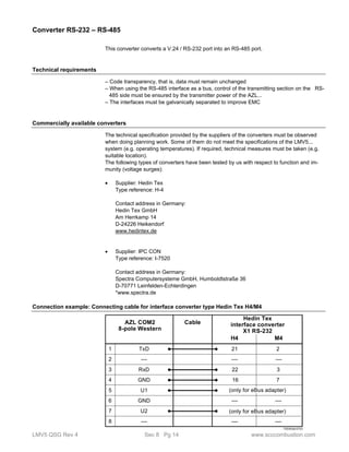
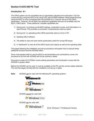
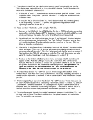
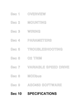
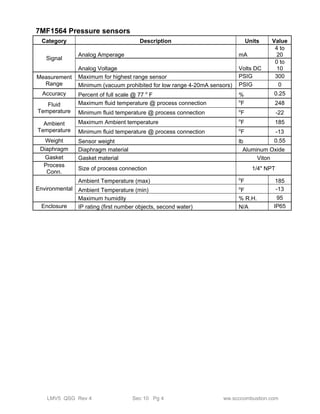
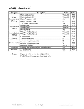
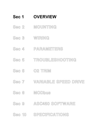
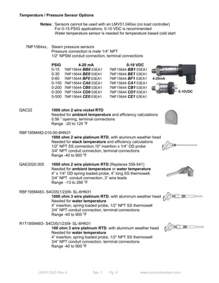
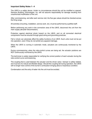
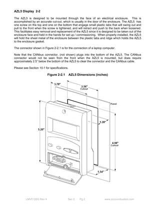
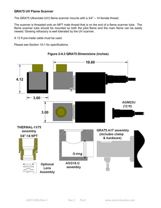
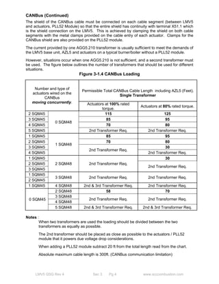
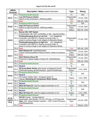
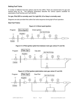
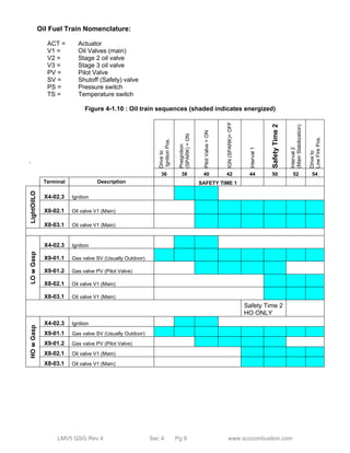
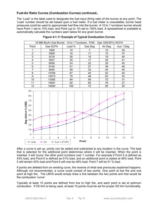
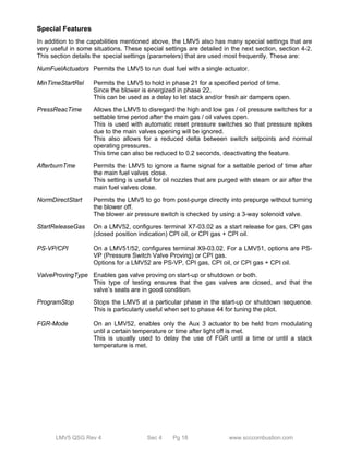
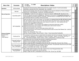
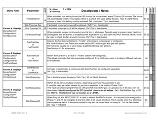
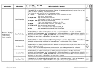
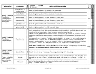
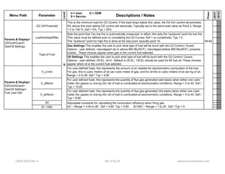
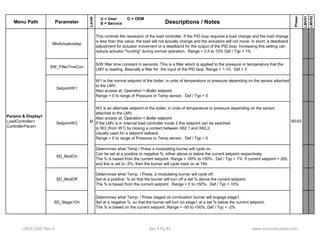
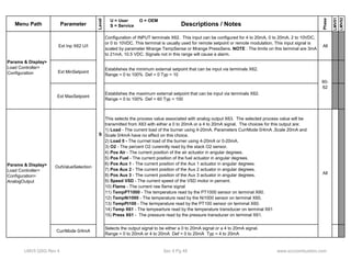
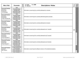
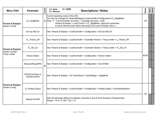
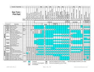
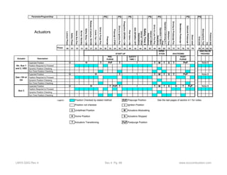
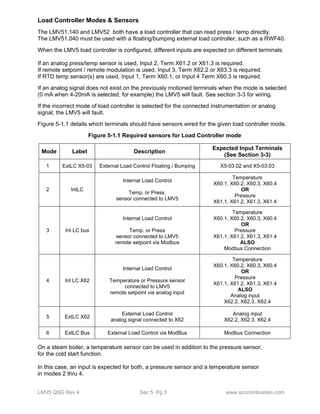
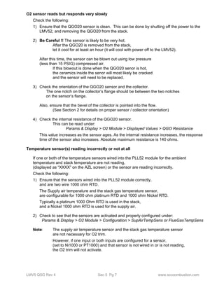
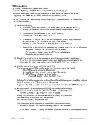
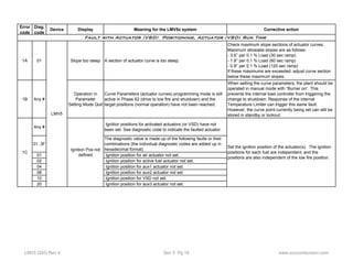
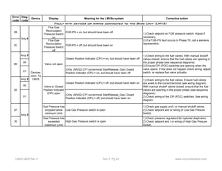
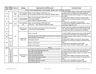
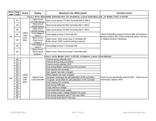
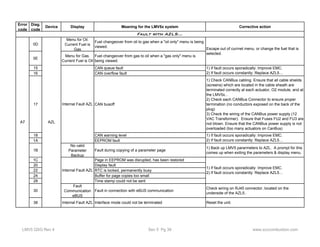
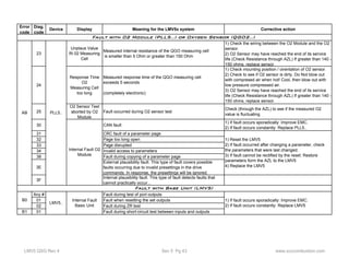
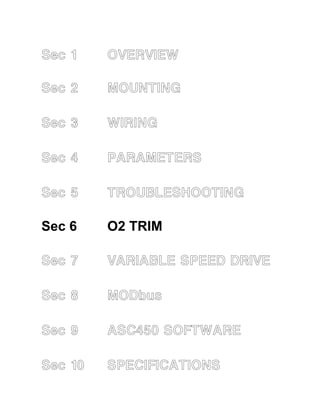
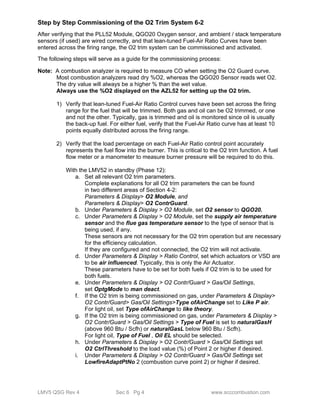
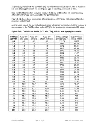
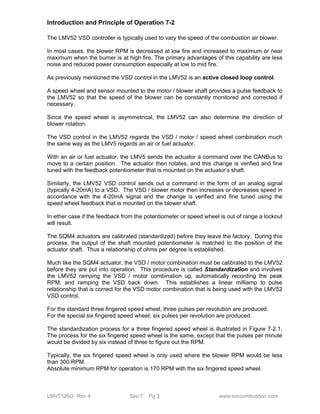
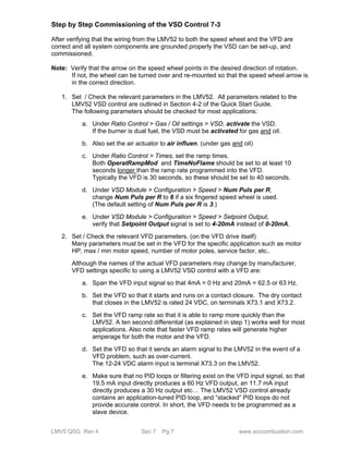
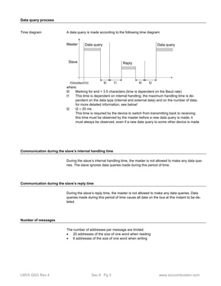
![Function Address Number
of
words
Data designation Access Data
format
Data type /
coding
Range Updating
rate
R 03/04
W 16
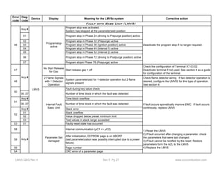
137 1 D-value R/W* U16 Seconds 0...1000 s Slow
03/04 400 16 Lockout history (current lockout) R U16/U32 [] Fast
03/04 416 16 Lockout history (current lockout -1) R U16/U32 [] Fast
03/04 432 16 Lockout history (current lockout -2) R U16/U32 [] Fast
: : : : : :
03/04 528 16 Lockout history (current lockout -8) R U16/U32 [] Fast
03/04 544 8 Error history (current error) R U16/U32 [] Fast
03/04 552 8 Error history (current error -1) R U16/U32 [] Fast
: : : : : :
03/04 704 8 Error history (current error -20) R U16/U32 [] Fast
* These parameters need not be continually written since they are stored in EEPROM,
which only permits a limited number of write accesses over its lifecycle (< 100,000)
Data structures
Date U16 Year
Month
Day
Time of day U16 Hour
Minute
Second
Lockout history U16 Error code
Error diagnostics
Error class
Error phase
Fuel
Output
Date: Year
Date: Month
Date: Day
Time of day: Hours
Time of day: Minutes
Time of day: Seconds
U32 Startup counter total
Hours run total
Error history U16 Error code
Error diagnostics
Error class
Error phase
Fuel
Dummy
Output
U32 Startup counter total
LMV5 QSG Rev 4 Sec 8 Pg 9 www.scccombustion.com](https://image.slidesharecdn.com/lmv5-quickstartguide-141111081345-conversion-gate02/85/Lmv5-quickstartguide-203-320.jpg)
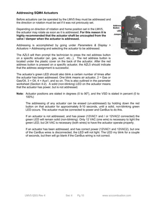
![Legend to address table
Access R Value can only be read
R / W Value can be read and written
Data format U16 16 bit integer, not subject to sign
S32 32 bit integer, subject to sign
Note:
In the AZL..., this data type is also used to
mark an invalid or non-available value by
using the value of «-1»
[ ] Data array
¹) Refer to section «Data structures»
* These parameters need not be continually written since they are stored in EEPROM,
which only permits a limited number of write accesses over its lifecycle (< 100,000)
Data types
TYPE Phys. Int. range Resolution Conversion int. / phys.
PT_PROZENT01 0...100 % 0...1000 0.1 % / 10
PT_PROZENTFU 0...110 % 0...1100 0.1 % / 10
PT_WINKEL -3.0...93.0° -30...930 0.1° / 10
PT_TEMP_
DRUCK
0...2000°
32...3632 °F
0...100 bar
0...1449 psi
0...2000
32...3632
0...1000
0...1449
1 °C
1 °F
0.1 bar
1 psi
1
1
/ 10
1
PT_LEISTUNG Modulating opera-tion:
0...100 %
Multistage opera-tion:
1001 = stage 1
1002 = stage 2
1003 = stage 3
0...1003 Modulating
operation:
0.1 %
Multistage
operation:
1
Modulating operation:
/ 10
Multistage operation:
- 1000
PT_ADAPTION 0: Undefined
1: Identification completed, parameter determined
2: Undefined
3: Adaption aborted by user
4: Temperature differential too small, temperature will be lowered with low-fire
5: Monitoring time running
6: Delivery of identification load set
7: Error during identification (path)
8: Error during identification (internally)
9: Monitoring time running
10: Changeover from modulating to multistage during an identification
11: Timeout monitoring time
12: Timeout heating output on path with monitoring
LMV5 QSG Rev 4 Sec 8 Pg 10 www.scccombustion.com](https://image.slidesharecdn.com/lmv5-quickstartguide-141111081345-conversion-gate02/85/Lmv5-quickstartguide-204-320.jpg)