Download to read offline
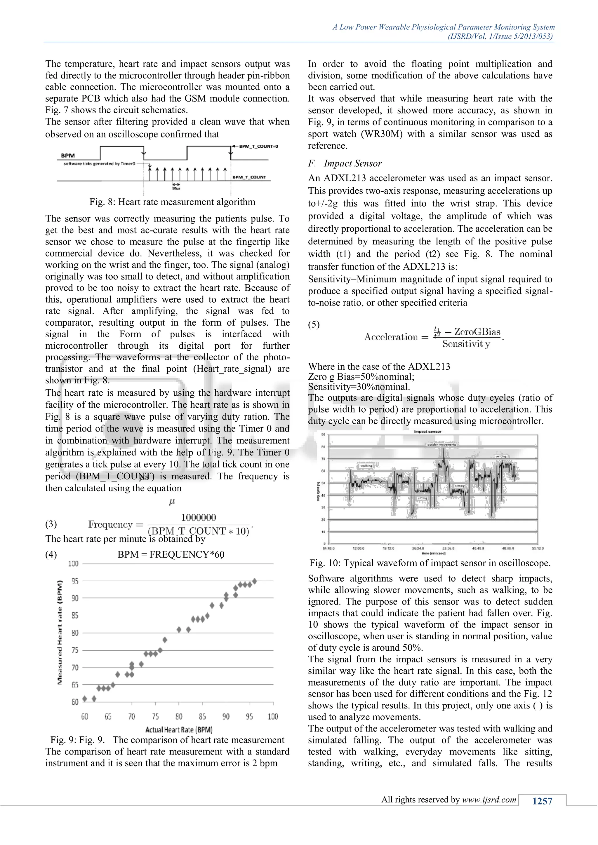
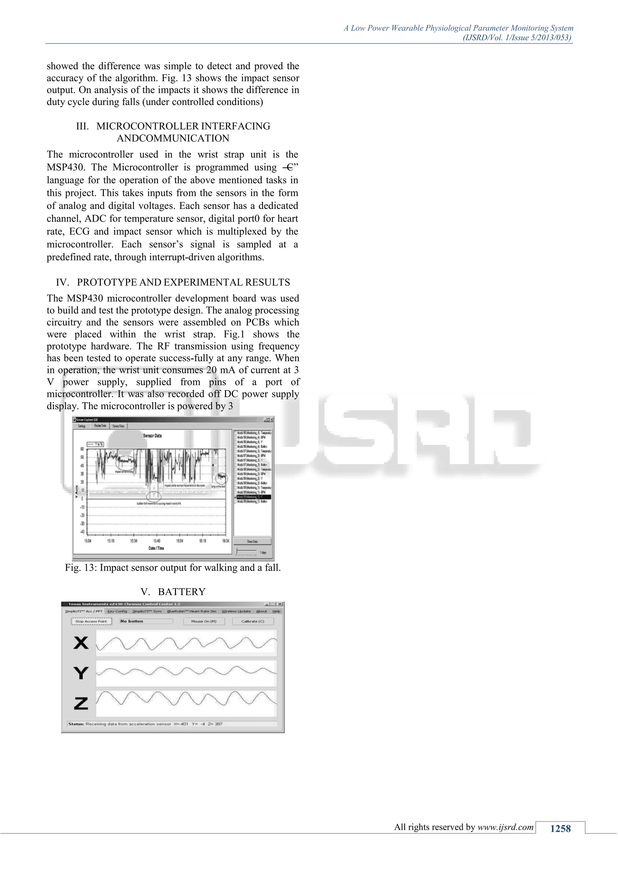

This paper presents the design and development of a low-power wearable physiological parameter monitoring system capable of tracking ECG signals, body temperature, and heartbeat for at-risk individuals. The system employs wireless sensors for continuous health monitoring in a home setting, facilitating early detection of emergencies like falls or health deterioration. The prototype has been tested successfully, showing promise for cost-effective telemedicine applications, particularly for the elderly and patients recuperating at home.