This document presents a modified True Single Phase Clock (TSPC) logic design style to implement high-speed pipelined circuits with improved performance. The modified style reduces transistor count by 40-50% compared to the standard TSPC style by allowing logic functions to be implemented using either the N-block or P-block. A 3-bit pipelined adder was designed using the modified style and showed a 46-47% reduction in transistors and 50% reduction in clock cycles compared to the standard style. The modified style offers benefits like lower transistor count, reduced latency, increased throughput, and lower power consumption for pipelined circuits.
![ACEEE International Journal on Communication, Vol 1, No. 1, Jan 2010
A High Speed Pipelined Dynamic Circuit
Implementation Using Modified TSPC Logic
Design Style With Improved Performance
Abhijit Asati and Chandrashekhar2
1
Birla Institute of Technology and Science, EEE Group, Pilani, India
Email: abhijitmicro@gmail.com
2
Central Electronics Engineering Research Institute, IC Design Group, Pilani, India
Email: chandra@ceeri.ernet.in
Abstract— The high-speed dynamic True Single Phase clock skew problem and increases the speed [1], [2],
Clock (TSPC) logic design style offer fully pipelined logic [8]. The TSPC Logic style shows a robust cell
circuits using only one clock signal, which makes clock characteristic and therefore the standard cell
distribution simple and compact. The conversion of simple implementation is possible. The TSPC-cell consists of
logic gates to pipelined TSPC logic gates increases transistor
count since standard cell implementation for a logic function
one N-block and one P-block each driven by single clock
uses both N-block as well as P-block to remove transparency signal (φ) [1], [2], [5], [7]. In standard TSPC logic style
between pipelined stages, despite the fact that logic the implementation of simple gates like AND, OR, XOR
functions are only implemented with N-block. In this paper increases the transistor count since each logic cell
we present a technique in which a TSPC logic cell are implementation use both N-block together with P-block
implemented both as cell_N and cell_P cells, where each cell to remove transparency between the pipelined stages,
block is performing a logic function along with only one while logic function is implemented only with N-block
type latching operation. Such an implementation allows a [3], [5]; therefore it makes the P-block redundant, since it
systematic approach for converting un-pipelined circuits to
perform no logic function other than latching. Although
fully pipelined circuits. The alternate cell_N and cell_P
behaves as dynamic register and removes transparency logic merging is possible [1], [2] in standard TSPC cell
between pipelined stages. The appropriate numbers of by implementing logic functions with both the N-block
dynamic registers are used to equalize stage delays for all and P-block, but such a logic merging is inefficient, since
paths and to remove transparency between pipelined stages. in practical cases inputs to a gate may appear after
The modified TSPC implementation shows almost 40% to different cycle delays, which may not allow effective
50% reduction in transistor counts and almost 50% logic merging. The implementation complexity also
reduction in clock cycles as compared to worst-case increases due to reduced freedom for logic merging; since
standard TSPC implementation. The worst-case standard it requires the careful and tedious mapping of logic
TSPC implementation assumes that no logic merging is
functions with both the blocks. The worst-case standard
possible with P-block, since input to any cell appears after
different cycle delays. The modified TSPC logic circuit TSPC logic implementation assumes that each cell logic
implementation preserves all the advantages of standard function is implemented with N-block only, while P-
TSPC logic implementation and in addition offers the block do not implement any logic but provide dynamic
reduced circuit complexity due to reduced transistor count latching to avoid the transparency between pipelined
per logic cell. The proposed logic design style reduces layout stages (i.e. no logic merging possible). Furthermore, the
area and average power consumption as compared to the pipelined circuit requires the stage registers (REG) to
standard TSPC pipelined circuit implementation. equalize the stage delays for all paths, which are
Index Terms—TSPC, dynamic, pipelined, high speed, implemented as one LATCH_N and LATCH_P in
transistor count, circuit complexity
cascade. In standard TSPC logic cells if logic merging is
not efficient, it increases pipelined stages that need the
I. INTRODUCTION extra register operation, which increases the transistor
Conventional static CMOS circuit implementation count [3], [6]. In this paper we present a technique in
cannot fulfill the requirements of high throughput which a TSPC logic cells are implemented as cell_N and
pipelined digital designs therefore dynamic logic circuits cell_P, where each cell is performing a logic function
can be used to speed-up digital designs. The high-speed along with only one type latching operation (either N-
dynamic True Single Phase Clock (TSPC) logic design latch or P-latch). The transparency between the pipelined
style offer fully pipelined logic circuits using only one stages can be removed by alternate cell_N and cell_P
clock signal, which makes clock distribution simple and assignment. Since each cell performs a logic operation
compact [1], [2], [8]. The simple clock distribution of the along with latching, such an implementation will reduce
TSPC circuits reduces the layout area for clock lines, no the number of redundant transistors due to efficient
merging of logic.
Footnotes: 8-point Times New Roman font; copyright credit, project
number, corresponding author, etc. The circuit complexity gets reduced due to decrease in
transistor count per logic cell. Since each cell performs
the logic function, therefore the burden of stage register
operations to equalize the stage delays for all paths gets
24
© 2010 ACEEE
DOI: 01.ijcom.01.01.06](https://image.slidesharecdn.com/06-120919010945-phpapp02/85/A-High-Speed-Pipelined-Dynamic-Circuit-Implementation-Using-Modified-TSPC-Logic-Design-Style-With-Improved-Performance-1-320.jpg)
![ACEEE International Journal on Communication, Vol 1, No. 1, Jan 2010
A High Speed Pipelined Dynamic Circuit
Implementation Using Modified TSPC Logic
Design Style With Improved Performance
Abhijit Asati and Chandrashekhar2
1
Birla Institute of Technology and Science, EEE Group, Pilani, India
Email: abhijitmicro@gmail.com
2
Central Electronics Engineering Research Institute, IC Design Group, Pilani, India
Email: chandra@ceeri.ernet.in
Abstract— The high-speed dynamic True Single Phase clock skew problem and increases the speed [1], [2],
Clock (TSPC) logic design style offer fully pipelined logic [8]. The TSPC Logic style shows a robust cell
circuits using only one clock signal, which makes clock characteristic and therefore the standard cell
distribution simple and compact. The conversion of simple implementation is possible. The TSPC-cell consists of
logic gates to pipelined TSPC logic gates increases transistor
count since standard cell implementation for a logic function
one N-block and one P-block each driven by single clock
uses both N-block as well as P-block to remove transparency signal (φ) [1], [2], [5], [7]. In standard TSPC logic style
between pipelined stages, despite the fact that logic the implementation of simple gates like AND, OR, XOR
functions are only implemented with N-block. In this paper increases the transistor count since each logic cell
we present a technique in which a TSPC logic cell are implementation use both N-block together with P-block
implemented both as cell_N and cell_P cells, where each cell to remove transparency between the pipelined stages,
block is performing a logic function along with only one while logic function is implemented only with N-block
type latching operation. Such an implementation allows a [3], [5]; therefore it makes the P-block redundant, since it
systematic approach for converting un-pipelined circuits to
perform no logic function other than latching. Although
fully pipelined circuits. The alternate cell_N and cell_P
behaves as dynamic register and removes transparency logic merging is possible [1], [2] in standard TSPC cell
between pipelined stages. The appropriate numbers of by implementing logic functions with both the N-block
dynamic registers are used to equalize stage delays for all and P-block, but such a logic merging is inefficient, since
paths and to remove transparency between pipelined stages. in practical cases inputs to a gate may appear after
The modified TSPC implementation shows almost 40% to different cycle delays, which may not allow effective
50% reduction in transistor counts and almost 50% logic merging. The implementation complexity also
reduction in clock cycles as compared to worst-case increases due to reduced freedom for logic merging; since
standard TSPC implementation. The worst-case standard it requires the careful and tedious mapping of logic
TSPC implementation assumes that no logic merging is
functions with both the blocks. The worst-case standard
possible with P-block, since input to any cell appears after
different cycle delays. The modified TSPC logic circuit TSPC logic implementation assumes that each cell logic
implementation preserves all the advantages of standard function is implemented with N-block only, while P-
TSPC logic implementation and in addition offers the block do not implement any logic but provide dynamic
reduced circuit complexity due to reduced transistor count latching to avoid the transparency between pipelined
per logic cell. The proposed logic design style reduces layout stages (i.e. no logic merging possible). Furthermore, the
area and average power consumption as compared to the pipelined circuit requires the stage registers (REG) to
standard TSPC pipelined circuit implementation. equalize the stage delays for all paths, which are
Index Terms—TSPC, dynamic, pipelined, high speed, implemented as one LATCH_N and LATCH_P in
transistor count, circuit complexity
cascade. In standard TSPC logic cells if logic merging is
not efficient, it increases pipelined stages that need the
I. INTRODUCTION extra register operation, which increases the transistor
Conventional static CMOS circuit implementation count [3], [6]. In this paper we present a technique in
cannot fulfill the requirements of high throughput which a TSPC logic cells are implemented as cell_N and
pipelined digital designs therefore dynamic logic circuits cell_P, where each cell is performing a logic function
can be used to speed-up digital designs. The high-speed along with only one type latching operation (either N-
dynamic True Single Phase Clock (TSPC) logic design latch or P-latch). The transparency between the pipelined
style offer fully pipelined logic circuits using only one stages can be removed by alternate cell_N and cell_P
clock signal, which makes clock distribution simple and assignment. Since each cell performs a logic operation
compact [1], [2], [8]. The simple clock distribution of the along with latching, such an implementation will reduce
TSPC circuits reduces the layout area for clock lines, no the number of redundant transistors due to efficient
merging of logic.
Footnotes: 8-point Times New Roman font; copyright credit, project
number, corresponding author, etc. The circuit complexity gets reduced due to decrease in
transistor count per logic cell. Since each cell performs
the logic function, therefore the burden of stage register
operations to equalize the stage delays for all paths gets
24
© 2010 ACEEE
DOI: 01.ijcom.01.01.06](https://image.slidesharecdn.com/06-120919010945-phpapp02/75/A-High-Speed-Pipelined-Dynamic-Circuit-Implementation-Using-Modified-TSPC-Logic-Design-Style-With-Improved-Performance-1-2048.jpg)
![ACEEE International Journal on Communication, Vol 1, No. 1, Jan 2010
reduced by almost 50% as compared to worst-case
standard TSPC logic implementation. The proposed
technique reduces the latency and increases the
throughput of digital pipelined circuit implementation
since the number of clock cycle gets reduced by almost
50%. The proposed logic design style offers advantages
like pipelining, low average power, low latency and high
throughput. A 3-bit pipelined adder is designed using
modified TSPC logic style and compared with standard
TSPC logic circuit implementation. Logic
implementation using the proposed logic design style is
described in Section II; circuit implementation is
discussed in Section III. Section IV shows the
comparison between standard TSPC and modified TSPC
and section V concludes the paper.
II. LOGIC IMPLEMENTATION
The proposed modified TSPC implementation allows
(a) AND_N
the flexibility of implementing logic function with both
N-block as well as with P-block, hence converting the
simpler logic cells to pipelined logic cells shows large
reduction in the transistor count as compared to standard
TSPC logic design style. The simple logic cells like
AND, OR, XOR can be designed using both N-block
logic cell as well as P-block logic cell, thus the logic cells
produced for AND function will be AND_N & AND_P;
OR, XOR in similar way produces OR_N & OR_P,
XOR_N & XOR_P respectively. A simple AND2 gate
can be implemented in two different ways (AND2_N and
AND2_P) as shown in Figure 1. The operations of
AND_N and AND2_P are shown in table I. REG can be
split into LATCH_N and LATCH_P. The latching can be
performed by these two latches are shown in Figure 2.
These latches are used to equalize cycle delays, since the
alternate LATCH_N and LATCH_P form a dynamic (b) AND_P
register REG [4]. Table II explains operation of both the
latches. For a pipelined circuit implementation the cell-N
and cell-P must be kept one after other in cascaded TABLE II. OPERATIONS OF LATCH_N AND LATCH_P
manner with appropriate latching to equalize stage delays
for all paths as explained in section III. The operation of
OPERATION OF LATCH_N
cell_N/cell_P and LATCH_N/LATCH_P are summarized
in table III.
A φ Y Comment
0 1 0 N1 is weak ON
TABLE I. OPERATION OF AND_N AND OPERATION OF AND_P
1 1 1 P1 strong ON
0 0 Latch Dynamic latch
OPERATION OF AND_N 1 0 Latch Dynamic latch
A B φ Y Comments OPERATION OF LATCH_P
0 0 0 0 Dynamic evaluation
0 1 0 0 Dynamic evaluation
1 0 0 0 Dynamic evaluation A φ Y Comment
1 1 0 1 Dynamic evaluation 0 0 0 N2 is strong ON
X X 1 Latch Dynamic latch 1 0 1 P2 weak ON
0 1 Latch Dynamic latch
OPERATION OF AND_P 1 1 Latch Dynamic latch
A B φ Y Comments
0 0 1 0 Dynamic evaluation
0 1 1 0 Dynamic evaluation
25
© 2010 ACEEE
DOI: 01.ijcom.01.01.06](https://image.slidesharecdn.com/06-120919010945-phpapp02/85/A-High-Speed-Pipelined-Dynamic-Circuit-Implementation-Using-Modified-TSPC-Logic-Design-Style-With-Improved-Performance-2-320.jpg)
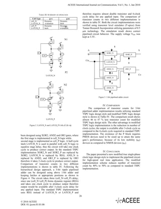
![ACEEE International Journal on Communication, Vol 1, No. 1, Jan 2010
B0 A0 B1 A1 B2 A2
φ φ
φ
Ci FA LATCH_N LATCH_N LATCH_N LATCH_N
S CO
φ
φ φ
LATCH_P LATCH_P LATCH_P LATCH_P
φ
LATCH_N
φ
FA LATCH_N LATCH_N
φ S CO
LATCH_P φ
φ
LATCH_P
φ LATCH_P
φ LATCH_N φ
LATCH_N
φ
φ FA
φ LATCH_P S CO
LATCH_P
S0 S1 S2 C2
Figure 4. 3-bit pipelined adder circuit
TABLE IV. COMPARISON TABLE
standard TSPC Modified TSPC
Cell No of No. of Sub Cell Type No of No. of Sub
transistor in Total cells transistor in Total
Type cells
each cell each cell
XOR2 6 19 114 XOR2_N/XOR2_P 6 13 78
AND2 9 13 117 AND2_N/AND2_P 9 7 63
OR3 3 14 42 OR3_N/ OR3_P 3 8 24
REG 21 11 231 LATCH_N/LATCH_P 21 5 105
The proposed logic style offers almost 50% reduction [3] Pareira, J.A. Michell, and J.M Solana “ Fully pipelined
in the number of clock cycle therefore the pipelined logic TSPC Barrel shifter for High-Speed Applications,” IEEE J.
circuit can be designed to offer reduced latency and Solid-State Circuits, Vol. 30, pp. 686-690, June 1996.
[4] Jiren Yuan and Christer Svensson, “High-speed CMOS
increased throughput as compared to standard TSPC
Circuit Technique,” IEEE J. Solid-State Circuits, Vol. 24,
circuit implementation. The proposed modified TSPC pp. 62-69, February 1989.
logic design style is best suited for converting un- [5] S. Flügel, F. Grassert, M. Grothmann, M. Haase, P.
pipelined circuits to fully pipelined circuits with effective Nimsch,H. Ploog, D. Timmermann, A. Wassatsch “A
logic merging. The circuit complexity reduces due to Design Flow for 12.8 GBit/s Triple DES using Dynamic
reduced number of transistors per logic cell. The Logic and Standard Synthesis Tools,” SNUG Europe-2001.
proposed logic style implementation offers compact [6] Johnny Pihl “Design Automation with the TSPC Circuit
layout area and the reduced average power consumption Technique: A High-Performance Wave Digital Filter,”
for pipelined circuit implementations. Use of single clock IEEE Transactions on very large scale integration (VLSI)
Systems, VOL. 8, NO. 4, pp. 456-459, August 2000
makes clock distribution simple and compact.
[7] Yuan ji-ren, Ingemar Karlsson, Christer Svensson, “A True
Single-Phase-Clock Dynamic CMOS Circuit Technique,”
REFERENCES IEEE J. Solid-State Circuits, Vol. SC-22, NO. 5, pp. 899-
[1] Jan M. Rabaey, Anantha Chandrakasan, Borivose Nikolic, 901, October 1987.
“Digital Integrated Circuits,” Second Edition Prentice–Hall [8] Seokjin Kim and Ramalingam Sridhar “Buffered Single-
of India Private Limited, 2004. phase Clocked Logic for High-speed CMOS Pipelined
[2] S.M. kang, Yusuf Leblebici, “CMOS Digital integrated Circuits,” 1997 IEEE International Symposium on Circuits
Circuits, Analysis and Design,” Third edition McGrawhill, and Systems, pp.1901-1903, June 9-12,1997, Hong Kong
2003.
27
© 2010 ACEEE
DOI: 01.ijcom.01.01.06](https://image.slidesharecdn.com/06-120919010945-phpapp02/85/A-High-Speed-Pipelined-Dynamic-Circuit-Implementation-Using-Modified-TSPC-Logic-Design-Style-With-Improved-Performance-4-320.jpg)