This document summarizes research on a four power-piston low-temperature differential Stirling engine using simulated solar energy as a heat source. Key findings include:
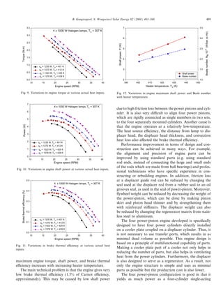
1) The engine was tested at various solar intensities up to a maximum of 1378 W and a heater temperature of 439 K.
2) At these maximum conditions, the engine produced a maximum torque of 2.91 N m, shaft power of 6.1 W, and brake thermal efficiency of 0.44% at 20 rpm.
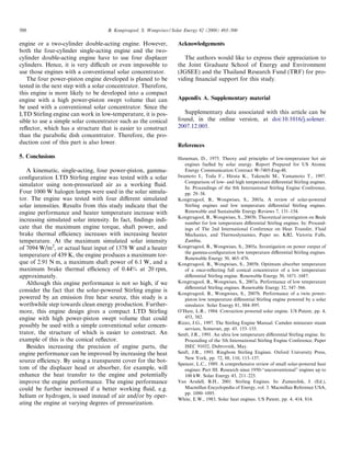
3) Research is summarized on using low-temperature heat sources for Stirling engines and measuring their performance characteristics including Beale number.
A solar ejector cooling system using refrigerant r141bMark Murray
This document describes a solar ejector cooling system that uses R141b as the working fluid. Key points:
- The system achieves a high coefficient of performance (COP) of 0.5 experimentally for single-stage cooling at a generation temperature of 90°C, condensing temperature of 28°C, and evaporating temperature of 8°C.
- For solar cooling, the overall COP is estimated to be around 0.22 at a generation temperature of 95°C, evaporating temperature of 8°C, and solar radiation of 700 W/m2.
- The solar ejector cooling system is simpler than absorption cooling systems and has potential for solar refrigeration applications with an optimum overall
This document analyzes the energy and exergy of an extraction back-pressure steam turbine used in a power plant in India. It evaluates the turbine's energy efficiency, exergy destruction, and exergy efficiency at 70% and 85% of maximum continuous rating. The analysis shows that operating the turbine at 85% rating improves the heat rate by 17.01 kJ/kWh, reducing CO2 emissions by 26.89 kg/h, SO2 emissions by 26.89 kg/h, and ash generation by 41.47 kg/day. Exergy, or the useful work potential of energy, provides a more complete analysis than energy alone by considering both quantity and quality of energy.
Thermal power plants generate electricity through combustion of fuels like coal and gas. The key components are the boiler, steam turbine, and electric generator. Control systems regulate critical functions like fuel and air management, steam temperatures, feedwater levels, and turbine speed. Supercritical plants operate at higher pressures and temperatures for greater efficiency. Combined cycle plants further improve efficiency by capturing waste heat from gas turbines to power additional steam turbines.
Using coolant modulation and pre cooling to avoid turbine bladeRakesh Rauth
This document examines methods to prevent turbine blade overheating when firing a gas turbine combined cycle power plant with low calorific value gas. Decreasing the firing temperature can prevent blade overheating but significantly reduces power output. Modulating the coolant supply to each blade row results in a much lower power penalty compared to under-firing. Pre-cooling the coolant before supplying it to the turbine further enhances power output by reducing the required coolant flow. Pre-cooling recovers 80% of the power gain possible from switching to low calorific value gas while providing higher combined cycle efficiency than under-firing.
Ash Cooler Heat Recovery Under Energy Conservation SchemeIJAPEJOURNAL
A healthy fluidization state in circulating fluidized-bed combustion (CFBC) combustor is attributed to proper quantity of hot bed material (ash), which acts as a thermal fly-wheel. It receives & stores thermal energy from the burning of fuel (lignite) & distributes uniformly throughout the combustor & helps in maintaining a sustained combustion. The quantity of bed ash inside the combustor or size of the bed, depends upon boiler load & subsequently upon combustor temperature, lignite feed rate and ash % in lignite. As these parameters varies during process continuously, sometimes it becomes necessary to drain out the ash from the combustor. As & when differential pressure across the bed is increased from a justified level, draining of hot bed ash starts into Ash Coolers. Bed ash is drained at very high temperature of 850 oC & it also contains burning particles of lignite. This paper describes the heat recovery from bed ash, unloaded from the combustor into ash cooler, by pre-heating the condensate water of turbine cycle in a 125 MW CFB boiler of Surat Lignite Power Plant in India. The thermal performance of ash cooler was derived by doing a heat balance calculation based on the measured temperature of ash and cooling water with different load. From the heat balance calculation influence of ash temperature and ash amount on heat transfer coefficient is determined. Simulation is carried out around main turbine cycle indicates improved thermal economy of the unit, higher plant thermal efficiency, lower plant heat rate and reduce fuel consumption rate. Also simulation result shows that the heat transfer coefficient increase with ash amount and decreases with increase in ash temperature.
Gas turbines operate using the Brayton cycle, which involves compressing air, adding heat through combustion at constant pressure, expanding the hot gases through a turbine, and rejecting heat at constant pressure. Early gas turbines had low efficiency around 17% but efficiency has increased through higher turbine inlet temperatures, more efficient components, and modifications like regeneration, intercooling, and reheating. Regeneration improves efficiency by heating the compressed air with the turbine exhaust, while intercooling and reheating involve multistage compression and expansion with cooling or heating between stages. Open cycle gas turbines exhaust combustion gases while closed cycle models re-circulate gases, improving efficiency but requiring more complex components.
Hrsg & turbine as run energy efficiency assessmentD.Pawan Kumar
The document provides measurements and performance data from an assessment of a heat recovery steam generator (HRSG) and steam turbine system. Key findings include:
- The HRSG achieved an overall thermal efficiency of 84.43% based on measured temperature and flow data.
- Heat was recovered across multiple components, with the high pressure evaporator recovering the most at 41.95% of total heat.
- The steam turbine achieved an overall efficiency of 78.40% based on measured steam and electrical output values.
This document summarizes the development of a small 50W class Stirling engine. Key points include:
- A gamma type Stirling engine was designed with a simple moving-tube heat exchanger and Rhombic mechanism. The target was 50W output at 4000rpm.
- Performance tests without load used air and showed the engine could run. Higher heat exchanger performance and lower mechanical losses are needed to reach targets.
- Mechanical loss measurements under pressure found friction torque increased linearly with speed. The viscosity coefficient was determined to be 2.03×10⁻⁴ (Nms).
Thermal Analysis and Optimization of a regenerator in a Solar Stirling engineRohith Jayaram
This document analyzes and optimizes the regenerator of a solar Stirling engine. It aims to minimize various losses in the regenerator that reduce engine efficiency. These losses include fluid friction, reheat, conduction through the matrix, temperature swing, and shuttle conduction. The document models heat transfer and fluid flow through the regenerator. It calculates expressions for each loss type based on regenerator geometry, material properties, and operating parameters. The objective is to determine optimal values for properties like wire diameter, porosity, and material to maximize heat transfer while minimizing losses and pressure drop through the regenerator matrix.
The document summarizes Chapter 7 of a textbook on thermodynamics. It includes in-text concept questions, concept problems, sections on heat engines/refrigerators, the second law and processes, Carnot cycles and absolute temperature, finite temperature heat transfer, and ideal gas Carnot cycles. It also includes review problems at the end. The chapter examines concepts related to heat engines, refrigerators, the second law of thermodynamics, and Carnot cycles.
This document discusses a steam power cycle with a closed feedwater heater (CFwH) that has drains cascaded backwards. It provides the T-s diagram for the cycle, noting that the terminal temperature difference (TTD) is typically around 3°C for the low-pressure heater and negative for the high-pressure heater due to superheating. Mass and energy balances must be applied to the heaters to analyze the cycle. An example problem is also provided to calculate values like steam extraction and pump work for a given set of temperatures.
Basic Scheme Open Cycle Gas Turbine Plant Aman Gupta
This document discusses open cycle gas turbine power plants. It begins with an introduction to gas power plants and the history of gas turbines. It then covers the basic working principle of gas turbine power plants, including the main components of air compressor, combustion chamber, and turbine. Applications and advantages/disadvantages of gas turbines are also summarized. Finally, it describes the open cycle gas power plant configuration and methods to improve the thermal efficiency, such as regeneration, reheating, and intercooling.
Gas turbines are internal combustion engines that produce power by burning an air-fuel mixture to spin a turbine and drive a generator. They work by compressing air, igniting the air-fuel mixture at high temperatures, spinning turbine blades with the hot gases, and using the spinning turbine to power a generator and produce electricity. Gas turbines can operate on a wide range of gaseous, liquid, and solid fuels. Fuel injectors introduce fuel into the combustion chamber in atomized form. Emissions like CO, NOx, and UHC are controlled through techniques like optimized fuel-air ratios, improved mixing, and exhaust gas recirculation. CFD analysis is used to study internal cooling schemes in turbine blades.
International Journal of Engineering Research and Applications (IJERA) is an open access online peer reviewed international journal that publishes research and review articles in the fields of Computer Science, Neural Networks, Electrical Engineering, Software Engineering, Information Technology, Mechanical Engineering, Chemical Engineering, Plastic Engineering, Food Technology, Textile Engineering, Nano Technology & science, Power Electronics, Electronics & Communication Engineering, Computational mathematics, Image processing, Civil Engineering, Structural Engineering, Environmental Engineering, VLSI Testing & Low Power VLSI Design etc.
This document summarizes a study that developed a calculation technique to determine the optimal size of flat panel solar thermoelectric systems for combined heat and power production. The technique directly calculates the heat and electric power output based on system parameters like solar irradiation, thermoelectric generator size, and temperatures. The technique was validated through experiments with five commercial thermoelectric generators of varying sizes. Both the calculated and measured results showed there is an optimum system size that achieves maximum heat and electric power output, demonstrating the effectiveness of the developed calculation technique.
1. The document discusses a gas turbine generator site with power demands of 23MW. The gas turbines on site are Siemens SGT-400 models rated at 13.9MW each.
2. It describes challenges with using higher hydrocarbon and hydrogen-rich fuels in gas turbines, such as increased risk of flashback and combustion instability. Heavier fuels require heating to maintain a suitable modified Wobbe index.
3. Solutions proposed include heating the fuel gas to adjust its Wobbe index, and rig testing of combustors with higher calorific value, high hydrogen fuels to evaluate performance.
This document provides information about a lecture on reheat and intercooling in gas turbine systems. It includes:
- An explanation of the concepts and purposes of using reheat and intercooling in gas turbines.
- An example problem calculating efficiency and mass flow rate for a gas turbine cycle with reheat and intercooling.
- Diagrams of gas turbine cycles with the different enhancements labeled.
This document discusses gas turbine power generation. It begins by defining a gas turbine as a machine that extracts mechanical power from flowing gases. It then discusses the key components of a gas turbine - the compressor, combustion chamber, and turbine. The compressed air is heated in the combustion chamber before expanding through the turbine. The document provides diagrams of open and closed gas turbine cycles. It discusses applications of gas turbines such as aircraft engines and power generation. It also covers topics like emissions, efficiency, and the needs for future gas turbine development.
The open gas-turbine cycle works as follows:
1. Air is compressed in a compressor, increasing its pressure and temperature.
2. The high-pressure air enters a combustion chamber where fuel is burned at constant pressure.
3. The high-temperature gas expands in a turbine, producing work and reducing to ambient pressure.
The Brayton cycle models the gas-turbine cycle with constant-pressure heat addition and rejection processes. Actual cycles have irreversibilities from non-isentropic compression/expansion and pressure drops. Efficiency can be improved with regeneration, intercooling, reheating, and multistage designs.
This document provides information on entropy and thermodynamics concepts including:
1. Entropy is a measure of irreversibilities and increases for all actual processes, being conserved only for idealized reversible processes.
2. Processes can only occur in the direction that complies with the increase of entropy principle.
3. Gas turbine cycles including Brayton, jet propulsion, and modifications like regeneration, intercooling and reheating are discussed. The efficiency and performance of these cycles depends on parameters like pressure and temperature ratios.
The document discusses steam power plant cycles. It begins by introducing the Rankine cycle as the ideal cycle for steam power plants. The Rankine cycle involves isothermal heat addition in a boiler, isentropic expansion in a turbine, isothermal heat rejection in a condenser, and isentropic compression in a pump. The document then discusses ways to increase the efficiency of the Rankine cycle, including lowering the condenser pressure, superheating steam to higher temperatures, increasing the boiler pressure, and adding reheat stages. Reheating steam between turbine stages allows higher boiler pressures without excessive moisture at the turbine exit. The ideal reheat Rankine cycle provides higher efficiency than a simple Rankine cycle.
Co2 emission rate per MWh of energy generated from coal fired plantsDavid Palmer, EIT
It has been proven that carbon dioxide emissions (greenhouse gases GHGs) absorb energy, slowing or preventing the loss of heat to space. In this way, GHGs act like a blanket, making Earth warmer than it would otherwise be. This process is commonly known as the “greenhouse effect”. How much GHGs are actually emitted from Ontario plants.
FINAL Report for Development of Enclosed Combustion Right for SCRAMJET Fuel S...Dan Martin
This document describes the development of an enclosed combustion rig to study ignition of fuels for scramjet engines. The rig uses an opposed jet burner configuration to produce a stable stagnation flame for experimentation. A double helix silicon carbide heating rod is inserted into the top burner to heat the opposing air flow and achieve ignition of fuel-air mixtures passing through the bottom burner. The rig has been tested and can sustain stable stagnation flames. Future work will quantify the effects of heated flow and calibrate the rig to ignite fuels and measure flame properties like ignition temperature, propagation speed, and extinction strain rate. This will provide data on cracked states of jet fuel to inform scramjet combustion design.
This document summarizes the key differences between open cycle and closed cycle gas turbines. It explains that open cycle gas turbines involve irreversible compression and expansion processes, while closed cycle gas turbines involve ideal isentropic compression and expansion. The document also discusses gas turbine cycles with intercooling and reheat to increase output, as well as regenerative cycles to improve efficiency. Additional sections cover the advantages of gas turbines over internal combustion engines and steam turbines.
This document provides a reference list of 78 CHP (combined heat and power) projects completed by BROAD Group between 2001 and 2008. It includes information such as the location, cooling and heating capacities, energy source, and generator type for each project. The projects range in size from 20kW to over 9000kW and served a variety of customers including universities, industrial plants, commercial buildings, and utilities in countries around the world.
This document provides definitions and explanations of various mechanical engineering terms related to mechanics, materials, thermodynamics, and manufacturing processes. Key terms defined include torque, stress, strain, stiffness, heat transfer, gear trains, welding, machine tools, and jigs/fixtures. Thermodynamics laws and concepts such as the first and second laws of thermodynamics and entropy are also summarized.
The document contains multiple choice and short answer questions related to thermodynamics and heat engines. Some sample questions include identifying the process represented by lines on a T-s diagram, defining key thermodynamic cycles like Otto and Diesel, and calculating efficiency and heat supplied for ideal Brayton cycles. Short answer questions provide definitions for terms like refrigerating capacity and differentiate concepts such as normal and shear stress. Numerical problems involve truss analysis and calculating properties of gas turbine cycles.
The document summarizes the regenerative feed water heating cycle used in steam power plants. It describes how steam from the turbine is used to preheat feedwater in heat exchangers before it enters the boiler. This improves the efficiency of the Rankine cycle by reducing the heat added from the boiler at the lower feedwater temperatures. The regenerative cycle captures additional heat from the steam that would otherwise be lost, improving the overall thermodynamic efficiency of the steam power generation process.
Analytical model for predicting the effect of operating speed on shaft powergargashrut91
The document presents an analytical model for predicting the relationship between operating speed and shaft power output of Stirling engines. The model uses a lumped mass approach to analyze transient temperature variations in the expansion and compression spaces. Results show that shaft power output initially increases with operating speed, reaches a maximum at a critical speed, and then decreases at higher speeds as temperature differences are reduced. Power output is also affected by parameters like air mass, thermal resistances, and regenerator effectiveness.
Analysis and design consideration of mean temperature differentialgargashrut91
This document presents the analysis and design considerations for a mean temperature differential Stirling engine intended for solar applications. The engine is designed to operate with a temperature difference of 300°C, assuming a constant heat source of 320°C from a solar dish concentrator and a 20°C heat sink. The mathematical model accounts for various losses in the engine, including pressure drops and heat transfer losses in the heat exchangers, internal conduction losses, external conduction losses through the regenerator, and shuttle heat transfer losses from the displacer movement. The model is used to optimize design parameters like swept volume and dead volume to maximize power output for a given operating frequency and temperature difference.
A Stirling engine is a heat engine that operates by cyclic compression and expansion of air or other gas (the working fluid) at different temperatures, such that there is a net conversion of heat energy to mechanical work. More specifically, a closed-cycle regenerative heat engine with a permanently gaseous working fluid.
1. The document summarizes the design, construction, and performance testing of a low temperature difference (LTD) Stirling engine.
2. The maximum efficiency of 24.52% was achieved at 74 rpm with a temperature difference of 71-91°C.
3. The study showed that LTD Stirling engines can be part of sustainable energy solutions when combined with renewable sources.
Iris Publishers- Journal of Engineering Sciences | Performance and Design Opt...IrisPublishers
The aim of this work is to optimize the design and performance of solar powered γ Stirling engine based on genetic algorithm (GA). A second-order mathematical model which includes thermal losses coupled with genetic algorithm GA has been developed and used to find the best values for different design variables. The physical geometry of the γ Stirling engine has been used as an objective variable in the genetic algorithm GA to determine the optimal parameters. The design geometry of the heat exchanger was considered to be the objective variable. The heater slots height, heater effective length, cooler slots height, cooler effective length, re-generator foil unrolled length and re-generator effective length are assumed to be the objective variables. Also, three different types of working fluids have been used in the model simulation to investigate the effect of the different working fluid on the engine performance. The comparison between the results obtained from the simulation by using the original parameters and the results from the optimized parameters when the engine was powered by solar energy; the higher temperature was 923 K applied to the working fluid when the air, helium, and hydrogen were used as working fluid. The engine power increases from 140.58 watts to 228.54 watts, and it is enhanced by approximately 50%, when the heating temperature is 923 K and the air is used as working fluid. The result showed that the working temperature is one of the most important parameters; because the output power increases by increasing of the hot side temperature.
1. The report analyzes heat exchange properties of small scale Stirling engines through experiments testing different materials for heat exchangers, working fluids, and the addition of fins.
2. The experiments found that copper heat exchangers performed best at higher temperatures, and that the working fluid helium produced higher engine performance than air or carbon dioxide.
3. The addition of fins to the engine provided no significant benefit to performance in low temperature Stirling engines.
The Design of Small Solar Thermal Dish Stirling 500 W Stand Alone in Thailand.Jack Wong
This document summarizes the design of a small 500W solar thermal dish Stirling system for use in Thailand. Key aspects include:
1. Thailand has average daily solar insolation of 550W/m2, requiring the system to be designed to operate at lower insolation levels than existing 1000W/m2 systems.
2. The design includes a 2.5m diameter parabolic dish, 4-cylinder gamma type Stirling engine with rotary drive mechanism and regenerator, able to produce 550W of power.
3. Testing of a prototype was conducted at AREF in Bangkok, showing it could produce 550W of power at an operating temperature of 650C and speed of 1200rpm when
Engine Block/Cylinder Block is the structure which contains the cylinders, and other parts, of an internal combustion engine. In an early automotive engine, the engine block consisted of just the cylinder block, to which a separate crankcase was attached. Engine block is affected by pressure and the thermal conditions happen inside the engine. So we come up with static structural and transient thermal analysis on the engine block. This report provides Stress, Strain and Total Deformation of Engine due to Pressure, Temperature and Heat Flux. We come up with the fatigue life of the Engine Block due to different loading conditions.
A cylinder block is an integrated structure comprising the cylinder(s) of a reciprocating engine and often some or all of their associated surrounding structures. The term engine block is often used synonymously with "cylinder block" The analysis of the combustion chamber is done by using different materials. By conducting the above analysis on the combustion chamber combustion rate, pressure and temperature gradient conditions are found and the best material for the combustion chamber is suggested.
Thermal analysis is conducted to find heat dissipation rate in engine block with the variation of materials Structural and fatigue analysis (dynamic) is conduct on engine block at working load conditions to evaluate and compare stress, strain, deformation and fatigue life with the variation of materials.
Frequency analysis is conducted on engine block with the variation of materials to evaluate frequency, Using these values material selection will be done, the value should be nearby previous one (cast iron) maximum accepted variation value 65HZ.
The document discusses closed cycle gas power plants. It begins with an introduction that defines closed cycle systems as those where a working gas like air is compressed, heated, expanded through a turbine to produce power, cooled, and recycled through the system. It then discusses the main components of closed cycle plants including compressors, combustion chambers, turbines, generators, and intercoolers. The working principle involves isentropic compression, constant pressure heating, isentropic expansion in the turbine, and constant pressure cooling. Key improvements discussed include higher operating temperatures through improved materials and cooling, and cycle modifications like regeneration to increase efficiency. Advantages are high efficiency while disadvantages include greater complexity versus open cycle plants.
Analysis of Energy Generation from Exhaust of Automobile using Peltier Thermo...ijtsrd
In recent past days, big deal of the automobile industry's RESEARCH and DEVELOPMENT Practicing on improving overall efficiency of vehicle. It has brought a major interest in the field of making internal combustion engines highly efficient 1 . In past days, only 25 30 energy is used in the vehicle and rest is exposed to surroundings. The useful energy is used to run the engine as well as generator. So the efficiency of those engine were very less. But the efficiency can be improved by utilizing waste heat that is exhaust of vehicle. One of the best technology that was found to be useful for this purpose were thermoelectric generator. In this, we study and investigated the use of thermoelectric generator for power production 2 . Thermoelectric generator works by imparting exhaust's gas stream on its surface and small D.C. electric current developed due to difference in temperature across heat exchanger that is put in the pathway of exhaust gas i.e. working on seebeck effect principle. An output Voltage of 200mV was generated using a single Bi2Te3 thermoelectric module for a temperature difference of about 40o C which can be used in charging battery, headlight, G.P.S. systems, etc. Such that it can reduce the level of alternator's frictional power that is used to save fuel and also in automotive industry to increase the efficiency of engine 1 . Naveen Kumar | Vaibhav Setia | Sunil Kumar Patel | Satyam Upadhyay, | Saurabh Chauhan, | Prakhar Bajpai ""Analysis of Energy Generation from Exhaust of Automobile using Peltier (Thermoelectric Generator)"" Published in International Journal of Trend in Scientific Research and Development (ijtsrd), ISSN: 2456-6470, Volume-3 | Issue-3 , April 2019, URL: https://www.ijtsrd.com/papers/ijtsrd22986.pdf
Paper URL: https://www.ijtsrd.com/engineering/transport-engineering/22986/analysis-of-energy-generation-from-exhaust-of-automobile-using-peltier-thermoelectric-generator/naveen-kumar
The document discusses Stirling engines and thermoelectric generators. It covers their configurations, design considerations, materials used, parts, types, calculations, efficiency, and applications. Stirling engines can convert heat into mechanical work through the compression and expansion of air or other gases. Thermoelectric generators directly convert temperature differences into electric voltage. Both have advantages like reliability and using wasted heat but also disadvantages like low efficiency.
The document discusses Stirling engines and their operation using biomass as fuel. Some key points:
- Stirling engines can run on various fuels and are simpler than internal combustion engines, making them suitable for biomass fuels.
- Thailand has potential for biomass energies from agricultural residues, and Stirling engines are a good option due to their simple design, quiet operation, and lack of emissions when using biomass.
- Stirling engines operate based on the Stirling thermodynamic cycle and are being investigated for sustainable power generation applications.
ANALYZE THE THERMAL PROPERTIES BY VARYING GEOMETRY, MATERIAL AND THICKNESS ...IAEME Publication
The Engine cylinder is one of the major automobile components, which is subjected to high temperature variations and thermal stresses. In order to cool the cylinder, fins are provided on the cylinder to increase the rate of heat transfer. By doing thermal analysis on the engine cylinder fins, it is helpful to know the heat dissipation inside the cylinder. The principle implemented in this project is to increase the heat dissipation rate The parametric model is created by varying the geometry, rectangular, circular and curved shaped fins and also by varying thickness of the fins. The main aim is to analysis thermal properties by varying geometry, material and thickness of cylinder fins.
Analyze the thermal properties by varying geometry material and thickness of ...IAEME Publication
The document summarizes research from multiple papers on analyzing the thermal properties of engine cylinder fins by varying the fin geometry, material, and thickness. The key points are:
1) A model of cylinder fins was created in ProEngineer and analyzed in ANSYS to determine temperatures, heat flux, and thermal gradients.
2) Simulations were run for rectangular fins made of materials like magnesium, aluminum alloys, and beryllium at thicknesses of 3mm and 2.5mm.
3) The simulations showed that reducing fin thickness from 3mm to 2.5mm increased heat transfer rates, with maximum rates reaching over 20W/mm2 for some materials.
International Journal of Computational Engineering Research (IJCER) is dedicated to protecting personal information and will make every reasonable effort to handle collected information appropriately. All information collected, as well as related requests, will be handled as carefully and efficiently as possible in accordance with IJCER standards for integrity and objectivity.
This document presents a summary of a dynamic model developed for simulating the operation of a steam turbine in a full scope power plant. It describes the basic components and types of steam turbines, including impulse and reaction turbines. It also discusses compounding methods used in steam turbines. The dynamic model accounts for thermal and rotational inertia effects during startup and shutdown. The model is used to analyze casing temperature variations over time during turbine operation. Simulation results from the model match actual plant operating data closely.
This document provides a review of previous research on thermoelectric generators. It begins with an introduction to solar energy and thermoelectric generation technologies. It then discusses the basic components of a thermoelectric module, including the thermocouple. The document reviews three previous works: 1) fabrication and testing of flat plate solar thermoelectric generators for near-earth orbits, which achieved power outputs of 3-3.3 watts; 2) development of a high efficiency thermoelectric power generator using bismuth telluride that achieved a maximum efficiency of 1.85%; 3) parametric analysis and modeling of a solar heat pipe thermoelectric generator unit comprising a thermoelectric module, finned heat pipe,
1) Reverend Dr. Robert Stirling studied divinity and became a minister before obtaining a patent for his "Heat Economiser" in 1816, now known as the regenerator, which he used to build the first practical Stirling engine in 1818.
2) The thermodynamic cycle driving Stirling engines, known as the Stirling cycle, involves four processes - two isothermal and two isometric - and was fully understood after the work of Sadi Carnot and others.
3) Recent studies have analyzed optimization of Stirling engine efficiency and power output, finite time thermodynamic effects, heat transfer and pressure losses in oscillating flow, and the effect of operating speed on output.
1) The document discusses heat transfer analysis methods to optimize the water cooling scheme for combustion devices used in torpedo propulsion systems.
2) It describes the components of the combustion chamber including the inner and outer walls that form the coolant passageway. Heat transfer is highest in the nozzle throat region.
3) Methods for calculating heat transfer rates, temperatures, velocities and other parameters on both the gas and coolant sides are presented using equations from heat transfer theory. The analysis can be used to optimize the cooling system design.
Heat Transfer Analysis to Optimize The Water Cooling Scheme For Combustion De...IJERA Editor
Thermal Propulsion system is one kind of propulsion system which is used to drive torpedo. The present study focuses mainly on design of combustion device known to be thrust chamber or thrust cylinder. The chamber and nozzle wall and the injector face plate must be made of metals selected for high strength at elevated temperature coupled with good thermal conductivity, resistance to high temperature oxidation. chemical inertness on the coolant on the coolant side, and suitability for the fabrication method to be employed. In the case of certain monopropellants, the metal must not catalyze the decomposition. Although aluminum and copper alloys have been used successfully for combustion chambers and nozzles, stainless steels and carbon steels are in widest use today.A cooling jacket permits the circulation of a coolant, which, in the case of flight engines is usually one of the propellants. Water is the only coolant recommended. The cooling jacket consists of an inner and outer wall. The combustion chamber forms the inner wall and another concentric but larger cylinder provides the outer wall. The space between the walls serves as the coolant passage. The nozzle throat region usually has the highest heat transfer intensity and is, therefore, the most difficult to cool.
Similar to A four power piston low-temperature differential stirling (20)
Heat Transfer Analysis to Optimize The Water Cooling Scheme For Combustion De...
A four power piston low-temperature differential stirling
1. Available online at www.sciencedirect.com
Solar Energy 82 (2008) 493–500
www.elsevier.com/locate/solener
A four power-piston low-temperature differential Stirling
engine using simulated solar energy as a heat source
Bancha Kongtragool, Somchai Wongwises *
Fluid Mechanics, Thermal Engineering and Multiphase Flow Research Laboratory (FUTURE), Department of Mechanical Engineering,
Faculty of Engineering, King Mongkut’s University of Technology Thonburi, Bangmod, Bangkok 10140, Thailand
Received 21 August 2007; received in revised form 3 December 2007; accepted 14 December 2007
Available online 11 January 2008
Communicated by: Associate Editor Robert Pitz-Paal
Abstract
In this paper, the performances of a four power-piston, gamma-configuration, low-temperature differential Stirling engine are pre-
sented. The engine is tested with air at atmospheric pressure by using a solar simulator with four different solar intensities as a heat
source. Variations in engine torque, shaft power and brake thermal efficiency with engine speed and engine performance at various heat
inputs are presented. The Beale number obtained from the testing of the engine is also investigated. The results indicate that at the maxi-
mum actual energy input of 1378 W and a heater temperature of 439 K, the engine approximately produces a maximum torque of
2.91 N m, a maximum shaft power of 6.1 W, and a maximum brake thermal efficiency of 0.44% at 20 rpm.
Ó 2008 Published by Elsevier Ltd.
Keywords: Stirling engine; Hot-air engine; Solar-powered heat engine; Solar simulator
1. Introduction (5) Displacer stroke is small.
(6) Dwell period at the end of the displacer stroke is
The low-temperature differential (LTD) Stirling engine slightly longer than the normal Stirling engine.
is a type of Stirling engine that can run with a small tem- (7) Operating speed is low.
perature difference between the hot and cold ends of the
displacer cylinder. The LTD Stirling engine is therefore While the Stirling engine has been studied by a large
able to operate with various low-temperature heat sources. number of researchers, the LTD Stirling engine has
Some characteristics of the LTD Stirling engine are as received comparatively little attention. Many studies
follows: related to solar-powered Stirling engines and LTD Stirling
engines have been reviewed in the authors’ previous works
(1) Displacer to power-piston swept volumes ratio or (Kongtragool and Wongwises, 2003a). Some of these
compression ratio is large. works are described as follows:
(2) Diameters of displacer cylinder and displacer are Haneman (1975) studied the possibility of using air with
large. low-temperature sources. This led to the construction of an
(3) Displacer length is short. unusual engine, in which the exhaust heat was still suffi-
(4) Effective heat transfer surfaces on both end plates of ciently hot to be useful for other purposes.
the displacer cylinder are large. A simply constructed low-temperature heat engine mod-
eled on the Stirling engine configurations was patented by
*
Corresponding author. Tel.: +662 4709115; fax: +662 4709111. White (1983). White suggested improving performance by
E-mail address: somchai.won@kmutt.ac.th (S. Wongwises). pressurizing the displacer chamber. Efficiencies were
0038-092X/$ - see front matter Ó 2008 Published by Elsevier Ltd.
doi:10.1016/j.solener.2007.12.005
2. 494 B. Kongtragool, S. Wongwises / Solar Energy 82 (2008) 493–500
Nomenclature
A absorber area (m2) q total heat input from heat source (W)
cp specific heat of water at constant pressure r dynamometer brake drum radius (m)
(4186 J/kg K) S spring balance reading (N)
EH heat source efficiency T engine torque (N m)
EBT brake thermal efficiency TC cooler wall temperature (K)
f engine frequency (Hz) TH heater wall temperature (K)
I average intensity on absorber plate (W/m2) Tw1 initial water temperature (K)
mw mass of water to absorb heat (kg) Tw2 final water temperature (K)
N engine speed (rpm, rps) t1 initial time at water temperature of Tw1 (s)
NB Beale number (W/bar cm3 Hz) t2 final time at water temperature of Tw2 (s)
P shaft power (W) VP power-piston swept volume (cc)
pm engine mean-pressure (bar) W loading weight (N)
qin actual heat input to the engine (W)
claimed to be around 30%, which is regarded as quiet high Kongtragool and Wongwises (2003b) investigated the
for a low-temperature engine. Beale number for LTD Stirling engines by collecting the
O’Hare (1984) patented a device which passed cooled existing Beale number data for various engine specifica-
and heated streams of air through a heat exchanger by tions from the literature. They concluded that the Beale
changing the pressure of air inside the bellows. The practi- number for a LTD Stirling engine could be found from
cal usefulness of this device was not shown in detail as in the mean-pressure power formula.
the case of Haneman’s work. Spencer (1989) reported that, Kongtragool and Wongwises (2005a) theoretically
in practice, such an engine would produce only a small investigated the power output of a gamma-configuration
amount of useful work relative to the collector system size, LTD Stirling engine. Former works on Stirling engine
and would give little gain compared to the additional main- power output calculations were studied and discussed.
tenance required. They pointed out that the mean-pressure power formula
Senft’s work (Senft, 1991) showed the motivation in the was the most appropriate for LTD Stirling engine power
use of Stirling engine. Their target was to develop an engine output estimation. However, the hot-space and cold-space
operating with a temperature difference of 2 °C or lower. working fluid temperatures were needed in the mean-pres-
Senft (1993) described the design and testing of a small sure power formula.
LTD Ringbom Stirling engine powered by a 60° conical Kongtragool and Wongwises (2005b) presented the opti-
reflector. He reported that the tested 60° conical reflector, mum absorber temperature of a once-reflecting full-conical
producing a hot end temperature of 93 °C under running reflector for a LTD Stirling engine. A mathematical model
conditions, worked very well. for the overall efficiency of a solar-powered Stirling engine
Rizzo (1997) reported that Kolin experimented with 16 was developed and the limiting conditions of both maximum
LTD Stirling engines, over a period of 12 years. Kolin pre- possible engine efficiency and power output were studied.
sented a model that worked on a temperature difference Results showed that the optimum absorber temperatures
between the hot and cold ends of the displacer cylinder obtained from both conditions were not significantly differ-
which was as low as 15 °C. Iwamoto et al. (1997) compared ent. Furthermore, the overall efficiency in the case of the
the performance of a LTD Stirling engine with a high-tem- maximum possible engine power output was very close to
perature differential Stirling engine. They concluded that that of the real engine of 55% Carnot efficiency.
the LTD Stirling engine efficiency at its rated speed was Kongtragool and Wongwises (2007a) also reported the
approximately 50% of the Carnot efficiency. However, performance of two LTD Stirling engines tested using
the compression ratio of their LTD Stirling engine was LPG gas burners as heat sources. The first engine was a
approximately equal to that of a conventional Stirling twin-power-piston engine and the second one was a four-
engine. Its performance, therefore, seemed to be the perfor- power-piston engine. Engine performances, thermal perfor-
mance of a common Stirling engine operating at a low mances, including the Beale’s numbers were presented.
operating temperature. Recently, Kongtragool and Wongwises (2007b) pre-
Senft Van Arsdell (2001) made an in-depth study of the sented the performance of a twin-power-piston Stirling
Ringbom engine and its derivatives, including the LTD engine powered by a solar simulator. This engine was the
engine. Senft’s research into LTD Stirling engines resulted same as the engine described in (Kongtragool and
in an interesting engine, which had an ultra-low tempera- Wongwises, 2007a). However, the heat source was a solar
ture difference of 0.5 °C. It has been very difficult for any- simulator made from a 1000 W halogen lamp. Compari-
one to create an engine with a result better than this. sons were made between the characteristics of the
3. B. Kongtragool, S. Wongwises / Solar Energy 82 (2008) 493–500 495
high-temperature differential (HTD) and LTD Stirling Table 1
engine and methods for performance improvement were Engine main design parameters
also discussed. Mechanical configuration Gamma
Although some information is currently available on the Power piston
LTD Stirling engine, there still remains room for further bore (cm) Â stroke (cm) 13.3 Â 13.3
research. In particular a detailed investigation is lacking swept volume (cm3) 7391
into the LTD Stirling engine using solar energy as a heat Displacer
source. As a consequence, in this paper, the testing of the bore (cm) Â stroke (cm) 60 Â 14.48
swept volume (cm3) 40,941
performance of a LTD Stirling engine using simulated
Compression ratio 5.54
solar energy is presented. The LTD Stirling engine tested Phase angle 90°
in this paper is a kinematics, single-acting, four power-
piston, gamma-configuration. Non-pressurized air is used
as a working fluid and a solar simulator fabricated from act as the crank discs for the power-pistons, are attached
four 1000 W tungsten halogen lamps is used as a heat to both ends of the crankshaft.
source. Since the gamma-configuration provides a large The power cylinders and pistons are made from steel.
regenerator heat transfer area and is easy to be constructed, The piston surfaces have brass lining and oil grooves,
this is configuration which is used in this study. 1 mm  1 mm with 10 mm spacing. The clearance between
piston and bore is approximately 0.02 mm. The displacer
cylinder and head is made from a 1 mm thick stainless steel
2. Experimental apparatus and procedure plate and the clearance between them is 2 mm. The displac-
er also serves as a regenerator, which is made from a
The engine schematic diagram and main design param- round-hole perforated steel sheet. The stainless steel pot
eters are shown in Fig. 1 and Table 1, respectively. To elim- scourer is used as a regenerator matrix.
inate the machining difficulties experienced with a single The displacer rod, made from a stainless steel pipe, is
large power-piston, it is designed with four single-acting guided by two brass bushings placed inside the displacer
power-pistons. Two power-pistons are connected with pis- rod guide house. Leakage through these bushings is pre-
ton rods and a flat bar (see Fig. 2). Four power cylinders vented by two rubber seals. Both ends of the power-piston
are directly connected to the cooler plate to minimize the and displacer connecting rod which are made from steel,
cold-space and dead volume transfer-port. Furthermore, are fitted with two ball bearings. Details of the testing facil-
the cooler plate is a part of the cooling water pan. ities are shown in Fig. 2. The intensity placed on the absor-
In order to make the engine compact and to minimize ber plate (or displacer head) is measured by a pyranometer
the number of engine parts, a simple crank mechanism is (Lambert model 00.16103.000000 CM3, calibrated con-
used in this engine. The crankshaft, which is supported stant of which is 23.66 lV/WmÀ2). The sensitivity of the
by two ball bearings, is made from a steel shaft, two crank intensity measurement obtained from the pyranometer is
discs and a crank pin. The crank pin is connected to the ±0.05%.
displacer connecting rod. Two steel flywheels, which also The cooler temperature (TC) and heater temperature
(TH) are measured by T-type and K-type thermocouples,
respectively. The accuracy of temperature measurement is
±0.1 °C. Four 1000 W tungsten halogen lamps (Osram
Crank disc Flywheel Haloline 64740 L J R7s) are used as a solar simulator. A
data logger (DataTaker model DT 50) is used to collect
Power piston
connecting rod
data from thermocouples and pyranometer.
Crankshaft bearing
The engine torque is measured by a rope-brake dyna-
Displacer Power piston
mometer. A displacer crank disc, which is 8.95 cm in
connecting rod cylinder radius, is used as a brake drum. The braking load is mea-
sured by the loading weight and spring balance reading.
Displacer guide A photo tachometer with ±0.1 rpm accuracy is used to
Displacer cylinder measure the engine speed. The engine tests are performed
using four distances from the lamp to the absorber. The
average simulated intensities (I) on the absorber plate are
5380, 5772, 6495, and 7094 W/m2. The actual heat input
to the engine (qin), at the above mentioned intensities, is
experimentally determined by using water to absorb this
heat. The concentrated heat (q) on the absorber plate,
actual heat input into the engine (qin), absorber tempera-
ture, and the engine performance (Pmax) resulting from
Fig. 1. Schematic diagram of the tested Stirling engine. these simulated intensities are shown in Table 2.
4. 496 B. Kongtragool, S. Wongwises / Solar Energy 82 (2008) 493–500
Flywheel
Flat bar
Piston rod
Weight hanger
Data logger
Thermocouple
Displacer cylinder
Halogen lamp
Thermocouple
Stopwatch
Digital tachometer
Loading weight Pyranometer
Fig. 2. Engine with testing facilities.
Table 2
Maximum engine performance and Beale number at TC = 307 K
I (W/m2) q (W) qin (W) TH (K) Tmax (N m) Pmax (W) EBTmax (%) NB (W/bar cm3 Hz)
5380 1521 1235 401 2.21 at 19.0 rpm 4.39 at 19.0 rpm 0.36 at 19.0 rpm 1.8757 Â 10À3
5772 1632 1272 412 2.96 at 15.3 rpm 4.87 at 18.8 rpm 0.38 at 18.8 rpm 2.1029 Â 10À3
6495 1837 1323 425 2.78 at 18.5 rpm 5.44 at 19.6 rpm 0.41 at 19.6 rpm 2.2532 Â 10À3
7094 2006 1378 439 2.91 at 20.0 rpm 6.10 at 20.0 rpm 0.44 at 20.0 rpm 2.4760 Â 10À3
3. Experimental procedures
3.1. Intensity test Solar simulator
A measurement of the actual intensity placed on the
absorber plate is needed for the engine performance calcu-
lation. The experiment for determination of the actual Pyranometer Data Logger
intensity on the engine absorber at various distances from
halogen lamp to absorber was carried out first. A pyranom-
eter was used to measure the intensity on the displacer
cylinder head that acted as the absorber plate. A data
Displacer cylinder
logger and a personal computer were used to collect data PC
from the pyranometer. The schematic diagram of this test
is shown in Fig. 3. The testing procedure was as follows: Fig. 3. Schematic diagram of the simulated solar intensity test.
5. B. Kongtragool, S. Wongwises / Solar Energy 82 (2008) 493–500 497
– The displacer cylinder and the halogen lamp were put on TW
the stand. Displacer cylinder
– The distance from the halogen lamp to the absorber Thermocouple
plate was set as required.
– The pyranometer was placed on the absorber plate at 17
positions as shown in Fig. 4.
Water Thermocouple
– The pyranometer was connected to the data logger and
computer. TH
– The halogen lamp was turned on and the intensity was
collected at that position.
– The pyranometer was placed to other positions. Solar simulator
– The testing was repeated for other intensities by chang-
ing the distance between lamp and absorber. Fig. 5. Schematic diagram of the heat source efficiency test.
The test results from those twelve distances are shown in
absorber. The test results from four intensities are shown
Fig. 7.
in Table 2.
The heat source efficiency (EH) can be determined from
3.2. Heat source test the following equation (Kongtragool and Wongwises,
2007b):
The actual or useful heat input can not be determined qin mw cp ðT w2 À T w1 Þ
directly while the engine is running due to difficulties EH ¼ ¼ ð1Þ
q IAðt2 À t1 Þ
caused by instrumentation. In order to determine the
actual heat input to the engine, therefore, this experiment where mw is the mass of water to absorb heat transferred
was carried out before the real performance test had begun. from the heat source, cp is the specific heat of water at con-
The schematic diagram of the heat source test is shown in stant pressure, Tw1 and Tw2 are the initial water tempera-
Fig. 5. The testing procedure was as follows: ture and the maximum water temperature, respectively, t1
The displacer cylinder, insulated with 25.4 mm thick and t2 are initial and final times at the water temperature
insulation was put on the stand. Thirty kg of water was of Tw1 and Tw2, respectively, I is the intensity from a solar
poured into the displacer cylinder. This water was used simulator, and A is the absorber area.
to absorb the heat from the solar simulator. The absorbed
heat was the useful heat input to the displacer cylinder. 3.3. Performance test
The thermocouples for measuring the displacer cylinder
head wall temperature and the water temperature were The schematic diagram of the engine performance test is
installed. Three T-type thermocouples were used to mea- shown in Fig. 6. Before the engine was started, all thermo-
sure the water temperature in the displacer cylinder, while couples were connected to the data logger and computer
three K-type thermocouples were used to measure the dis-
placer cylinder head wall temperatures.
The halogen lamp was placed at the required distance, Brake Drum
Digital Tachometer
underneath the displacer cylinder head. The initial water
temperature was recorded and the halogen lamp was
turned on. Before the boiling point was reached, all tem-
peratures were taken at every 1-min interval using a data Spring Balance
Loading Weight
logger and personal computer.
The testing was repeated with another heat input by TC Thermocouple
changing the distance between the halogen lamp and the
Cooling water inlet Cooling water outlet
Stirling engine
520 mm diameter Thermocouple
320 mm diameter TH
Pyranometer Solar simulator
Fig. 6. Schematic diagram of the four power-piston Stirling engine
Fig. 4. Positions of pyranometer in the simulated solar intensity test. performance test by a solar simulator.
6. 498 B. Kongtragool, S. Wongwises / Solar Energy 82 (2008) 493–500
8000 ized engines, the pm = 1 bar is used in the calculation as de-
Heat source: 4 x 1000 W Halogen lamp
7000
scribed by Senft (1993).
Experimental data
Average intensity (W/m2)
6000
4. Experimental results and discussion
5000
4000 In the engine test, as the load is gradually applied to the
3000
engine, its speed is gradually reduced, until eventually it
stops. The characteristics are shown in the form of the vari-
2000 ation of torque, shaft power and brake thermal efficiency
1000 with the engine speed. Only engine performance at the
maximum average simulated intensity is presented as a typi-
0
0 200 400 600 800 1000 1200
cal performance as shown in Fig. 8.
Distance from lamps to absorber (mm) From Fig. 8, it can be noted that the engine torque
decreases with increasing engine speed. Furthermore, the
Fig. 7. Average intensity on absorber plate versus distance from lamp to
absorber.
shaft power increases with increasing engine speed until
the maximum shaft power is reached and then decreases
with increasing engine speed. This decreasing shaft power
and the cooling water system was connected to the engine after the maximum point, results from the friction that
cooling pan. The cooling water flow rate was adjusted in increases with increasing speed together with inadequate
order to keep water level in the cooling pan constant. Some heat transfer at higher speed. Since the brake thermal effi-
lubricating oil was ejected into the power-pistons, cylin- ciency is the shaft power divided by a constant heat input,
ders, and the displacer guide bushing. the curve of brake thermal efficiency has the same trend as
The solar simulator was placed underneath the displacer the shaft power.
head at a specified distance. The halogen lamp was then Figs. 9–11 show the variations of engine torque, shaft
switched on. The displacer head was heated up until it power and brake thermal efficiency with engine speed at
reached the operating temperature. The engine was then various heat inputs, respectively. As expected, greater
started and run until a steady condition was reached. engine performance results from the higher heat input.
The engine was loaded by adding a weight to the dyna- An increase of the engine torque, shaft power and brake
mometer. After that, the engine speed reading, spring bal- thermal efficiency is shown to also depend on the heater
ance reading and all temperatures reading from the temperature.
thermocouples were collected. Another loading weight In Fig. 12, the maximum shaft power and Beale number
was added to the dynamometer until the engine was at various heat inputs are plotted against the heater tem-
stopped. The actual shaft power (P) can be calculated perature. As shown in this figure, the shaft power and
from: Beale number increase with an increase in heater
P ¼ 2pTN ¼ 2pðS À W ÞrN ð2Þ temperature.
Results from this study indicate that the engine perfor-
where T is the engine torque, S is the spring balance read- mance and heater temperature increase with increasing
ing, W is the loading weight, r is the brake drum radius, simulated solar intensity. In fact, it can be said that the
and N is the engine speed.
Testing was then repeated with another simulated inten-
sity by changing the distance from the lamp to absorber. 7
2
0.6
I = 7094 W/m , qin = 1378 W, TH = 439 K, TC = 307 K
The actual heat input to the engine (qin) at the above
6
mentioned intensities, was experimentally determined by 0.5
Torque (N.m) and Power (W)
using water to absorb the heat. The concentrated heat (q) 5
on absorber plate, actual heat input to the engine, absorber 0.4
Efficiency, %
temperature, and engine performance resulting from these 4
0.3
simulated intensities are shown in Table 2. In this table,
3
the brake thermal efficiency EBT is calculated from:
0.2
2
EBT ¼ P =qin ð3Þ
Torque 0.1
1
The Beale number is calculated from the Beale formula Shaft power
(Kongtragool and Wongwises, 2003b, 2005a): Brake thermal efficiency
0 0.0
15 20 25 30 35 40
N B ¼ P =ðpm V P f Þ ð4Þ Engine speed (RPM)
Where pm is engine mean-pressure, VP is power-piston Fig. 8. Engine performance at 7094 W/m2 average intensity, 1378 W
swept volume and f is engine frequency. For non-pressur- actual heat input.
7. B. Kongtragool, S. Wongwises / Solar Energy 82 (2008) 493–500 499
3.5 7 3.5
4 x 1000 W Halogen lamps, TC = 307 K
Beale number, NB 10-3 (W/bar cc Hz)
3.0
6 3.0
2.5
Shaft power, P (W)
Torque (N.m)
5 2.5
2.0
1.5
4 2.0
1.0
qin = 1235 W, TH = 401 K
qin = 1272 W, TH = 412 K 3 1.5
0.5 qin = 1323 W, TH = 425 K Shaft power
qin = 1378 W, TH = 439 K Beale number
0.0 2 1.0
10 15 20 25 30 35 40 390 400 410 420 430 440 450
Engine speed (RPM) Heater temperature, TH (K)
Fig. 9. Variations in engine torque at various actual heat inputs. Fig. 12. Variations in engine maximum shaft power and Beale number
with heater temperature.
7
4 x 1000 W Halogen lamps, TC = 307 K
due to high friction loss between the power pistons and cyli-
6
nder. It is also very difficult to align four power pistons,
5
which are rigidly connected as single members in two sets,
to the four separately mounted cylinders. Another cause is
Power (W)
4 that the engine operates at a relatively low-temperature.
The heat source efficiency, the distance from lamp to dis-
3
placer head, the displacer head thickness, and convection
2
heat loss also affected the brake thermal efficiency.
qin = 1235 W, TH = 401 K
qin = 1272 W, TH = 412 K Performance improvement in terms of design and con-
1 qin = 1323 W, TH = 425 K struction can be achieved in many ways. For example,
qin = 1378 W, TH = 439 K the alignment and precision of engine parts can be
0
10 15 20 25 30 35 40 improved by using standard parts (e.g. using standard
Engine speed (RPM) rod ends, instead of connecting the large and small ends
of the rods which are made from ball bearings) and profes-
Fig. 10. Variations in engine shaft power at various actual heat inputs.
sional technicians who have specific experience in con-
structing or rebuilding engines. In addition, friction loss
0.5 at a displacer guide rod can be reduced by changing the
4 x 1000 W Halogen lamps, TC = 307 K
seal used at the displacer rod from a rubber seal to an oil
0.4
grooves seal, as used in the seal of power-piston. Moreover,
Brake thermal efficiency (%)
flywheel weight can be reduced by decreasing the weight of
the power-piston, which can be done by making piston
0.3
skirt and piston head thinner and by strengthening them
with reinforced stiffeners. The displacer weight can also
0.2 be reduced by changing the regenerator matrix from stain-
less steel to aluminum.
qin = 1235 W, TH = 401 K
0.1 qin = 1272 W, TH = 412 K
The four power-piston engine developed is specifically
qin = 1323 W, TH = 425 K designed to have four power cylinders directly installed
qin = 1378 W, TH = 439 K on a cooler plate coupled on a displacer cylinder. Thus, it
0.0
10 15 20 25 30 35 40 is not necessary to use transfer ports, which results in as
Engine speed (RPM) minimal dead volume as possible. This engine design is
based on a principle of multifunctional capability of parts.
Fig. 11. Variations in brake thermal efficiency at various actual heat
inputs.
Making a cooler plate part of a cooler not only helps in
reducing the number of parts, but also helps in ventilating
heat from the power cylinders. Furthermore, the displacer
maximum engine torque, shaft power, and brake thermal is also designed to serve as a regenerator. As a result, not
efficiency increases with increasing heater temperature. only the engine structure is simple and uses as minimal
The main technical problem is that the engine gives very parts as possible but the production cost is also lower.
low brake thermal efficiency (1.5% of Carnot efficiency, The four power-piston configuration is good in that it
approximately). This may be caused by low shaft power yields as much power as a four-cylinder single-acting
8. 500 B. Kongtragool, S. Wongwises / Solar Energy 82 (2008) 493–500
engine or a two-cylinder double-acting engine. However, Acknowledgements
both the four-cylinder single-acting engine and the two-
cylinder double-acting engine have to use four displacer The authors would like to express their appreciation to
cylinders. Hence, it is very difficult or even impossible to the Joint Graduate School of Energy and Environment
use those engines with a conventional solar concentrator. (JGSEE) and the Thailand Research Fund (TRF) for pro-
The four power-piston engine developed is planed to be viding financial support for this study.
tested in the next step with a solar concentrator. Therefore,
this engine is more likely to be developed into a compact
engine with a high power-piston swept volume that can Appendix A. Supplementary material
be used with a conventional solar concentrator. Since the
LTD Stirling engine can work in low-temperature, it is pos- Supplementary data associated with this article can be
sible to use a simple solar concentrator such as the conical found, in the online version, at doi:10.1016/j.solener.
reflector, which has a structure that is easier to construct 2007.12.005.
than the parabolic dish concentrator. Therefore, the pro-
duction cost of this part is also lower.
References
5. Conclusions Haneman, D., 1975. Theory and principles of low-temperature hot air
engines fuelled by solar energy. Report Prepared for US Atomic
A kinematic, single-acting, four power-piston, gamma- Energy Communication Contract W-7405-Eng-48.
configuration LTD Stirling engine was tested with a solar Iwamoto I., Toda F., Hirata K., Takeuchi M., Yamamoto T., 1997.
Comparison of low- and high temperature differential Stirling engines.
simulator using non-pressurized air as a working fluid.
In: Proceedings of the 8th International Stirling Engine Conference,
Four 1000 W halogen lamps were used in the solar simula- pp. 29–38.
tor. The engine was tested with four different simulated Kongtragool, B., Wongwises, S., 2003a. A review of solar-powered
solar intensities. Results from this study indicate that the Stirling engines and low temperature differential Stirling engines.
engine performance and heater temperature increase with Renewable and Sustainable Energy Reviews 7, 131–154.
Kongtragool, B., Wongwises, S., 2003b. Theoretical investigation on Beale
increasing simulated solar intensity. In fact, findings indi-
number for low temperature differential Stirling engines. In: Proceed-
cate that the maximum engine torque, shaft power, and ings of The 2nd International Conference on Heat Transfer, Fluid
brake thermal efficiency increases with increasing heater Mechanics, and Thermodynamics, Paper no. KB2, Victoria Falls,
temperature. At the maximum simulated solar intensity Zambia.
of 7094 W/m2, or actual heat input of 1378 W and a heater Kongtragool, B., Wongwises, S., 2005a. Investigation on power output of
the gamma-configuration low temperature differential Stirling engines.
temperature of 439 K, the engine produces a maximum tor-
Renewable Energy 30, 465–476.
que of 2.91 N m, a maximum shaft power of 6.1 W, and a Kongtragool, B., Wongwises, S., 2005b. Optimum absorber temperature
maximum brake thermal efficiency of 0.44% at 20 rpm, of a once-reflecting full conical concentrator of a low temperature
approximately. differential Stirling engine. Renewable Energy 30, 1671–1687.
Although this engine performance is not so high, if we Kongtragool, B., Wongwises, S., 2007a. Performance of low temperature
differential Stirling engines. Renewable Energy 32, 547–566.
consider the fact that the solar-powered Stirling engine is
Kongtragool, B., Wongwises, S., 2007b. Performance of a twin power-
powered by an emission free hear source, this study is a piston low temperature differential Stirling engine powered by a solar
worthwhile step towards clean energy production. Further- simulator. Solar Energy 81, 884–895.
more, this engine design gives a compact LTD Stirling O’Hare, L.R., 1984. Convection powered solar engine. US Patent, pp. 4,
engine with high power-piston swept volume that could 453, 382.
Rizzo, J.G., 1997. The Stirling Engine Manual. Camden miniature steam
possibly be used with a simple conventional solar concen-
services, Somerset, pp. 43. 153–155.
trator, the structure of which is easier to construct. An Senft, J.R., 1991. An ultra low temperature differential Stirling engine. In:
example of this is the conical reflector. Proceeding of the 5th International Stirling Engine Conference, Paper
Besides increasing the precision of engine parts, the ISEC 91032, Dubrovnik, May.
engine performance can be improved by increasing the heat Senft, J.R., 1993. Ringbom Stirling Engines. Oxford University Press,
New York, pp. 72, 88, 110, 113–137.
source efficiency. By using a transparent cover for the bot-
Spencer, L.C., 1989. A comprehensive review of small solar-powered heat
tom of the displacer head or absorber, for example, will engines: Part III. Research since 1950-‘‘unconventional” engines up to
enhance the heat transfer to the engine and potentially 100 kW. Solar Energy 43, 211–225.
improve the engine performance. The engine performance Van Arsdell, B.H., 2001. Stirling Engines. In: Zumerchik, J. (Ed.),
could be further increased if a better working fluid, e.g. Macmillan Encyclopedia of Energy, vol. 3. Macmillan Reference USA,
pp. 1090–1095.
helium or hydrogen, is used instead of air and/or by oper-
White, E.W., 1983. Solar heat engines. US Patent, pp. 4, 414, 814.
ating the engine at varying degrees of pressurization.