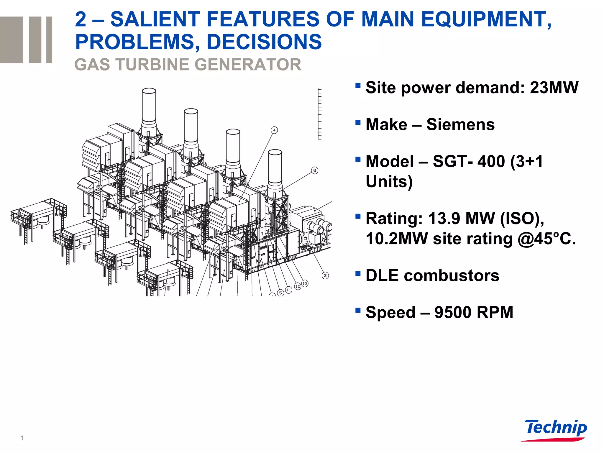
1
GAS TURBINE GENERATOR
 Site power demand: 23MW
 Make – Siemens
 Model – SGT- 400 (3+1
Units)
 Rating: 13.9 MW (ISO),
10.2MW site rating @45°C.
 DLE combustors
 Speed – 9500 RPM
2 – SALIENT FEATURES OF MAIN EQUIPMENT,
PROBLEMS, DECISIONS
Footer can be customized2
Typical Gas Turbine
Typical Gas Turbine
Gas Turbine Combustor
Footer can be customized3
Blue Lines represents Compressed Air
from Axial compressor
Red Lines Represents Fuel Gas and
Hot Gases
DLN / DLE
Combustor
Comparison of Flame Speeds
Footer can be customized4
Flame Speed
Ar-Ratawi Fuel Gas composition
Footer can be customized5
Footer can be customized6
Heavier Hydrocarbon, Flash back
H2, Flash back
Inert Gases,
Blown Out
Fuel Gas Mapping
• High hydrocarbon fuels are significantly more reactive and energetic (Similar to H2) compared to
natural gas.
• Wobbe Index: The index defines the heating value of a quantity of gas that will flow through a
hole of a given size in a given amount of time. The higher the index the higher the heating value.
Footer can be customized7
 Blown Out. Blown out occurs when the flame becomes detached from the location where it is anchored and
is physically “blown out” of the combustor. Due to low WI, Mass flow rate of fuel through injector will increase
(As it is required to provide the same Heat release) resulting in Pressure drop with possible flame
detachment Result : Dynamic Pressure Amplitudes Solution : Changing the Fuel Injector Nozzle design
(High inert gas components)
 Flashback. Flashback occurs when the turbulent flame speed exceeds the flow velocity (Gas Velocity of gas
before combustion), allowing the flame to propagate upstream into the premixing section (Which is not
designed for higher temperature). (High Hydrogen and Higher Hydrocarbons components)
 When Flashback occurs acoustic oscillations in the premixer section causes fluctuations in the fuel and/or air
supply rates, thus producing a reactive mixture whose equivalence ratio changes periodically in time. Result :
Mixture fluctuation is transferred to the flame where it produces heat release oscillations that drive the
Combustion instability.
 Combustion Instability. Combustion instabilities are characterized by large amplitude pressure oscillations
that are driven by unsteady heat release
 Due to Heavier Hydrocarbons / Hydrogen in fuel
composition will Increase the flame speed and change
flame Centre of Mass (Increasing the Burner Metal
Temp.).
 Chances of Hot spot due to shorter convection
time in the combustor.
Footer can be customized8
 Modified Wobbe Index (MWI): By increasing the fuel supply temp wobbe index is altered from
ISO conditions. The fuel supply temperature impacts the actual volumetric fuel flow.
“All gas mixtures that have the same Wobbe number will give the same amount of heat.”
MWI=LHV/(SG * Tgas) 0.5
LHV = Lower heating value of the gas in Btu/scf
SG = Specific gravity of the gas fuel related to air
Tgas= Absolute temperature of the gas fuel in oR
Ethane content vol % 10 15 20 25 30 35 40 45 50
Min Supply Temp C 2.5 3.0 11.0 20.0 29.0 37.0 46.0 54.0 63.0
Dew Point C < -20 < -20 < -20 < -20 < -20 < -20 < -20 < -20 < -20
Temp Corr Wobbe Index kj/m3 48214 48939 48991 48957 48926 48975 48946 48993 48965
Wobbe Index @ iso kj/m3 47156 47909 48650 49380 50101 50811 51513 52205 52888
For standard SGT-400 operation,
Siemens generally accept fuels within
a MWI range 37 – 49MJ/m3.
SOLUTION 1 : Heating the Fuel Gas (Heavier
Hydrocarbon)
Footer can be customized9
SOLUTION 2: RIG TESTING OF COMBUSTORS (High Calorific value High H2)
COMBUSTORS
Footer can be customized10
TEST ARRANGMENT
Footer can be customized11
TYPICAL RESULTS

High Ethane Fuel Gas_ Combustors

  • 1.
    1 GAS TURBINE GENERATOR Site power demand: 23MW  Make – Siemens  Model – SGT- 400 (3+1 Units)  Rating: 13.9 MW (ISO), 10.2MW site rating @45°C.  DLE combustors  Speed – 9500 RPM 2 – SALIENT FEATURES OF MAIN EQUIPMENT, PROBLEMS, DECISIONS
  • 2.
    Footer can becustomized2 Typical Gas Turbine Typical Gas Turbine
  • 3.
    Gas Turbine Combustor Footercan be customized3 Blue Lines represents Compressed Air from Axial compressor Red Lines Represents Fuel Gas and Hot Gases DLN / DLE Combustor
  • 4.
    Comparison of FlameSpeeds Footer can be customized4 Flame Speed
  • 5.
    Ar-Ratawi Fuel Gascomposition Footer can be customized5
  • 6.
    Footer can becustomized6 Heavier Hydrocarbon, Flash back H2, Flash back Inert Gases, Blown Out Fuel Gas Mapping • High hydrocarbon fuels are significantly more reactive and energetic (Similar to H2) compared to natural gas. • Wobbe Index: The index defines the heating value of a quantity of gas that will flow through a hole of a given size in a given amount of time. The higher the index the higher the heating value.
  • 7.
    Footer can becustomized7  Blown Out. Blown out occurs when the flame becomes detached from the location where it is anchored and is physically “blown out” of the combustor. Due to low WI, Mass flow rate of fuel through injector will increase (As it is required to provide the same Heat release) resulting in Pressure drop with possible flame detachment Result : Dynamic Pressure Amplitudes Solution : Changing the Fuel Injector Nozzle design (High inert gas components)  Flashback. Flashback occurs when the turbulent flame speed exceeds the flow velocity (Gas Velocity of gas before combustion), allowing the flame to propagate upstream into the premixing section (Which is not designed for higher temperature). (High Hydrogen and Higher Hydrocarbons components)  When Flashback occurs acoustic oscillations in the premixer section causes fluctuations in the fuel and/or air supply rates, thus producing a reactive mixture whose equivalence ratio changes periodically in time. Result : Mixture fluctuation is transferred to the flame where it produces heat release oscillations that drive the Combustion instability.  Combustion Instability. Combustion instabilities are characterized by large amplitude pressure oscillations that are driven by unsteady heat release  Due to Heavier Hydrocarbons / Hydrogen in fuel composition will Increase the flame speed and change flame Centre of Mass (Increasing the Burner Metal Temp.).  Chances of Hot spot due to shorter convection time in the combustor.
  • 8.
    Footer can becustomized8  Modified Wobbe Index (MWI): By increasing the fuel supply temp wobbe index is altered from ISO conditions. The fuel supply temperature impacts the actual volumetric fuel flow. “All gas mixtures that have the same Wobbe number will give the same amount of heat.” MWI=LHV/(SG * Tgas) 0.5 LHV = Lower heating value of the gas in Btu/scf SG = Specific gravity of the gas fuel related to air Tgas= Absolute temperature of the gas fuel in oR Ethane content vol % 10 15 20 25 30 35 40 45 50 Min Supply Temp C 2.5 3.0 11.0 20.0 29.0 37.0 46.0 54.0 63.0 Dew Point C < -20 < -20 < -20 < -20 < -20 < -20 < -20 < -20 < -20 Temp Corr Wobbe Index kj/m3 48214 48939 48991 48957 48926 48975 48946 48993 48965 Wobbe Index @ iso kj/m3 47156 47909 48650 49380 50101 50811 51513 52205 52888 For standard SGT-400 operation, Siemens generally accept fuels within a MWI range 37 – 49MJ/m3. SOLUTION 1 : Heating the Fuel Gas (Heavier Hydrocarbon)
  • 9.
    Footer can becustomized9 SOLUTION 2: RIG TESTING OF COMBUSTORS (High Calorific value High H2) COMBUSTORS
  • 10.
    Footer can becustomized10 TEST ARRANGMENT
  • 11.
    Footer can becustomized11 TYPICAL RESULTS