Download to read offline
![International Journal of Innovative Research in Advanced Engineering (IJIRAE) ISSN: 2349-2763
Issue 12, Volume 2 (December 2015) www.ijirae.com
____________________________________________________________________________________________________________
IJIRAE: Impact Factor Value - ISRAJIF: 1.857 | PIF: 2.469 | Jour Info: 4.085 | Index Copernicus 2014 = 6.57
© 2014- 15, IJIRAE- All Rights Reserved Page -23
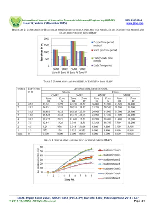
b:The Average displacement in special moment resisting frame is about 40% lesser than that of in ordinary moment resisting frame
obtained by Etabs Software.
c: The Average displacement obtained by Etabs software is almost same that of obtained by Stadd.Pro. software.
d: The max. Average displacement occurred at top story of the building .
e: The min. Average displacement occurred at bottom story of the building.
f: The pattern of storey wise variation of average displacement is same in special moment resisting frame and ordinary moment
resisting frame.
g: The Average displacement under seismic zone III is 33.33% lower than that of under seismic zone IV.
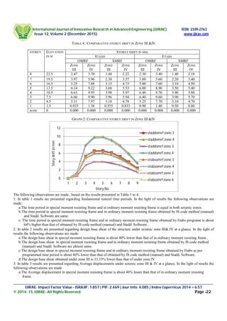
4: In table 4 results are presented regarding story drift under zone III&IV at a glance. In the light of results the following observations
are made:
a:The Story drift in special moment resisting frame is 40% lesser than that of in ordinary moment resisting frame obtained by
Stadd. Pro. Software.
b: The Story drift in special moment resisting frame is 40% lesser than that of in ordinary moment resisting frame obtained by
Etabs Software.
c: The Story drift obtained by Etabs software is almost same that of obtained by Stadd.Pro. Software.
d: The max. Story drift occurred at mid story of the building.
e: The of variation of story drift is increasing in nature from bottom story to mid story and decreasing in nature from midstory to
top story of building.
f: The min. Story drift is at bottom floor.
g:The Storey drift under seismic zone III is 33.33% lower than that of under seismic zone IV.
4. CONCLUSION
In view of the results and observations obtained by the analysis of the considered building structures, following primary conclusions
on the prediction of the concern thesis topic could be made as under.
a:The SMRF structural system is more efficient than OMRF structural system in earthquake design because for a particular
seismic zone, design base shear , average displacement and story drift for SMRF is 40% lower than that of OMRF.
b:The design of buildings using Etabs software as per programmed calculated fundamental natural time period will be more
economical design than that of Stadd.Pro. software because design base shear obtained in first case is 40% lower than that of
second case.
5. SCOPE FOR FUTURE WORK
a:Another field of wide research could be the analysis and design of moment resisting frames considering the infill walls and
shear walls as a part of the structure.
b:The study of seismic behavior of structural system could be extended using one another software.
c:The study of seismic behavior of structural system could be extended considering more than two seismic zones
REFRENCES
[1]. ACI Committee 318, ACI, Structural Building Code and Commentary, American Concrete Institute, 2002.
[2]. Applied Technology Council, ATC 40, Seismic Evaluation and Retrofit of Concrete Buildings, Volume 1-2, California, 1996.
[3]. Army Corps of Engineers, Seismic Evaluation and Rehabilitation for Buildings, US. Washington, 1999.
[4]. Association of Bay Area Governments, ABAG Earthquake and Hazards Program-Mitigation Policy Review, 2005.
[5]. Athanassiadou C.J., Seismic Performance of RC Plane Frames Irregular in Elevation, Engineering Structures, doi:10.1016/
j.engstruct. 2007.07. 2015, 2007.
[6]. Attard T. and Fafitis A., Modeling of Higher-Mode Effects Using an OptimalMulti-Modal Pushover Analysis, Earthquake
Resistant Engineering Structures V, 2005.
[7]. Bayülke N., Kuran F., Dogan A., Kocaman C., Memis H. and Soyal L., Nonlinear Pushover Analysis of Reinforced Concrete
Structures and Comparison with Earthquake Damage, 5th National Conference on Earthquake Engineering, AT-108, Turkey,
2003.
[8]. Chang S. and Kim. S., Structural Behaviour of Soft Story Buildings, National Earthquake Engineering Congress, (449-459),
1994.
[9]. Chintanapakdee C. and Chopra A.K., Evaluation of Modal Pushover Analysis Using Generic Frames, Earthquake Engineering
and Structural Dynamics, Vol. 32, (417-442), 2003.
[10]. Chintanapakdee C. and Chopra A., Evaluation of The Modal Pushover Analysis Procedure Using Vertically Regular and
Irregular Generic Frames, A Report on Research Conducted under Grant No. CMS-9812531 from the National Science
Foundation, 2003.](https://image.slidesharecdn.com/04-160220141159/85/A-COMPARATIVE-STUDY-OF-OMRF-SMRF-STRUCTURAL-SYSTEM-USING-DIFFERENT-SOFTWARES-6-320.jpg)

This study examines the seismic behavior of Ordinary Moment Resisting Frames (OMRF) and Special Moment Resisting Frames (SMRF) using software like STADD.Pro and ETABS, focusing on their performance in seismic zones III and IV in India. The results indicate that SMRF structures demonstrate better ductility and resistance to earthquake forces compared to OMRF structures, as highlighted by analyses including fundamental natural time periods, base shear, and storey displacements. The findings emphasize the need for improved earthquake-resistant design practices in Indian construction to mitigate increasing seismic risks.