The document describes an anti-collision system for shiploaders with the following goals:
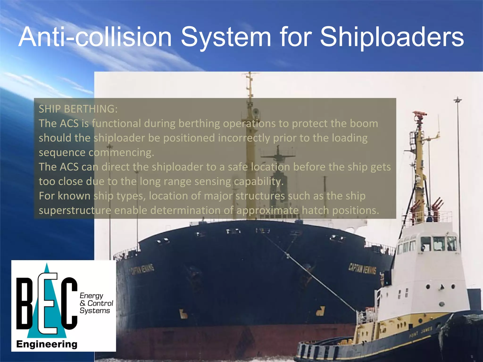
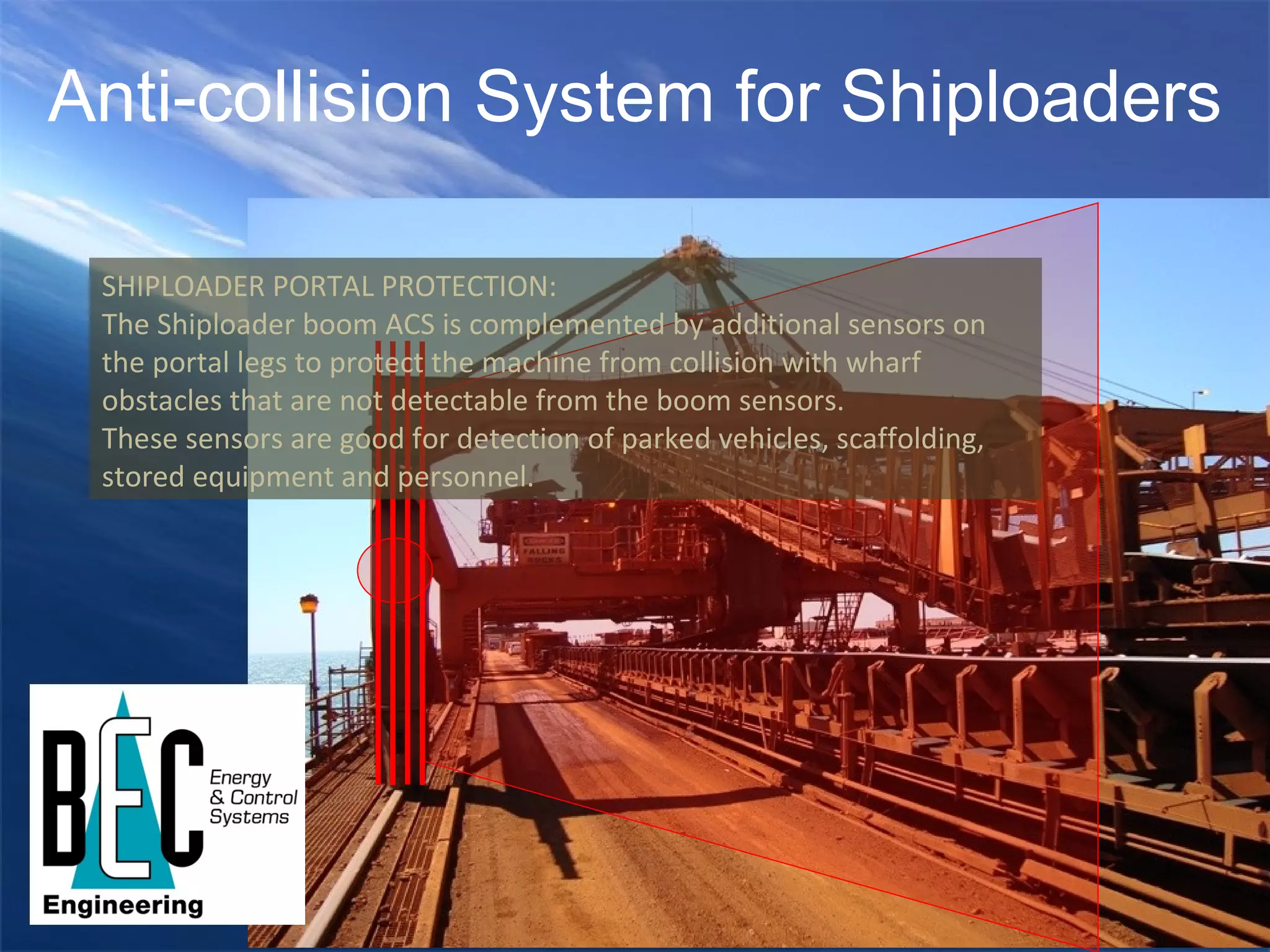
1) Provide fully dynamic and autonomous protection for the shiploader boom from collisions with the ship, wharf, and other moving objects.
2) Maintain a high level of safety integrity for unmanned operation.
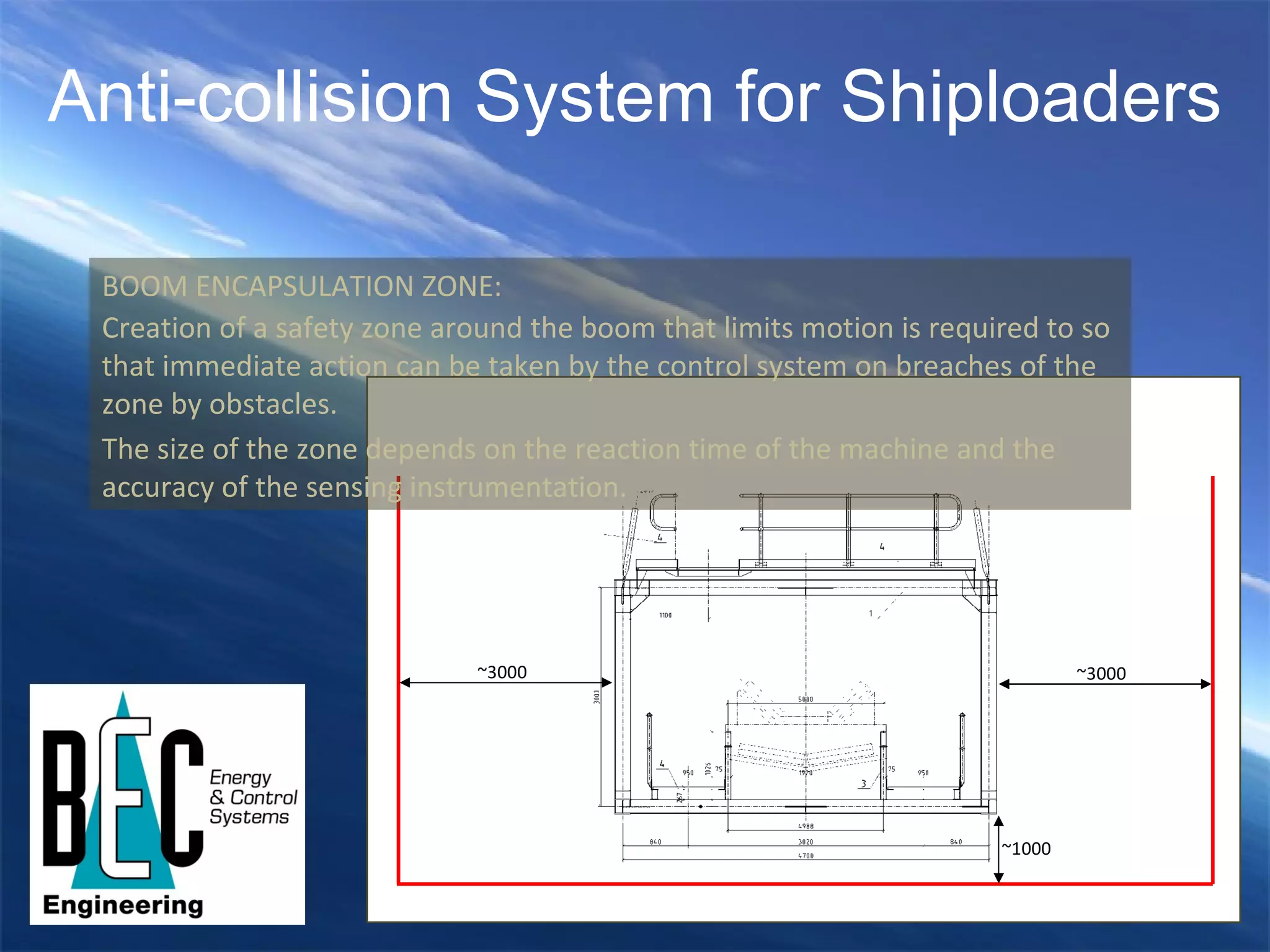
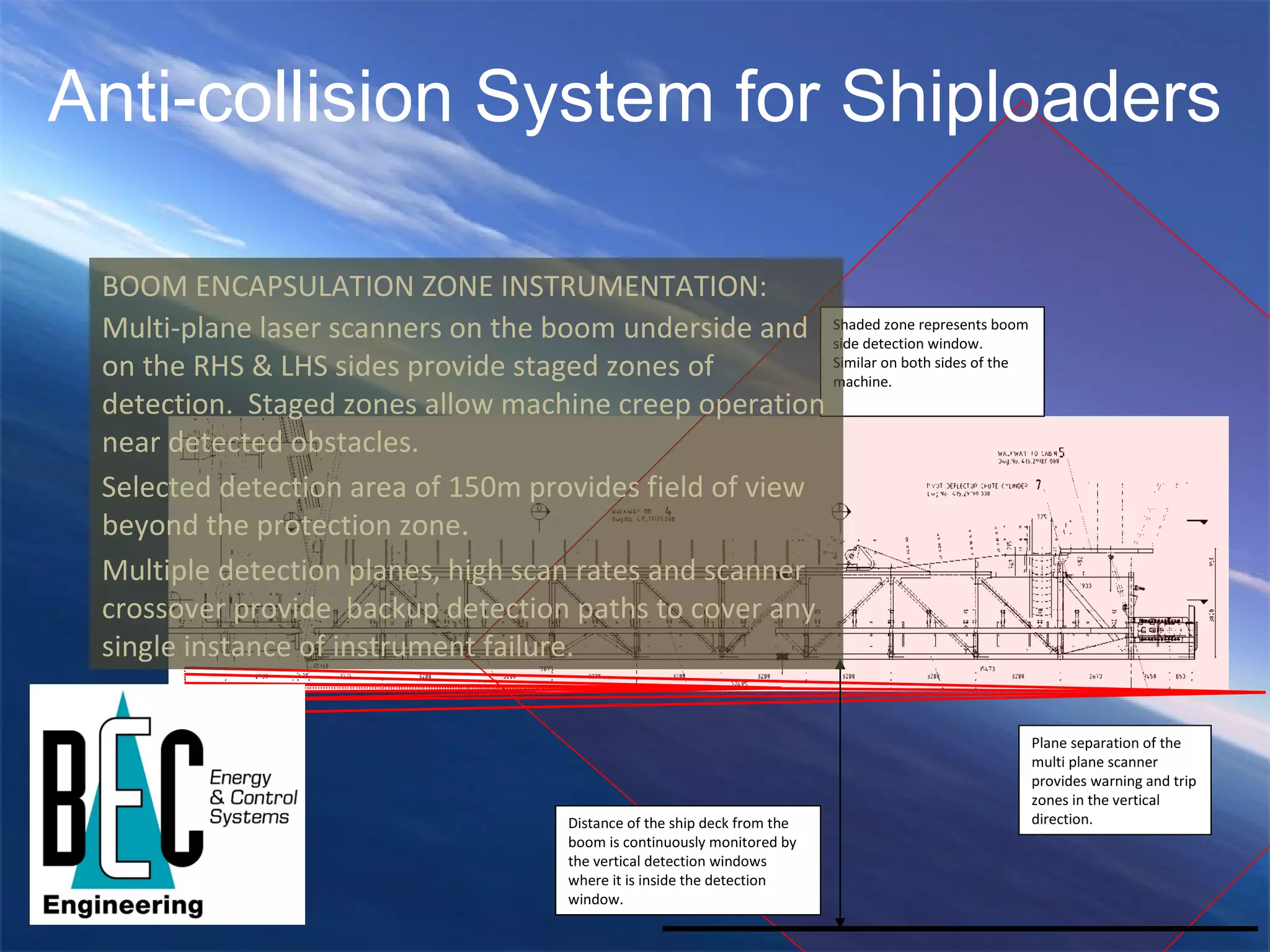
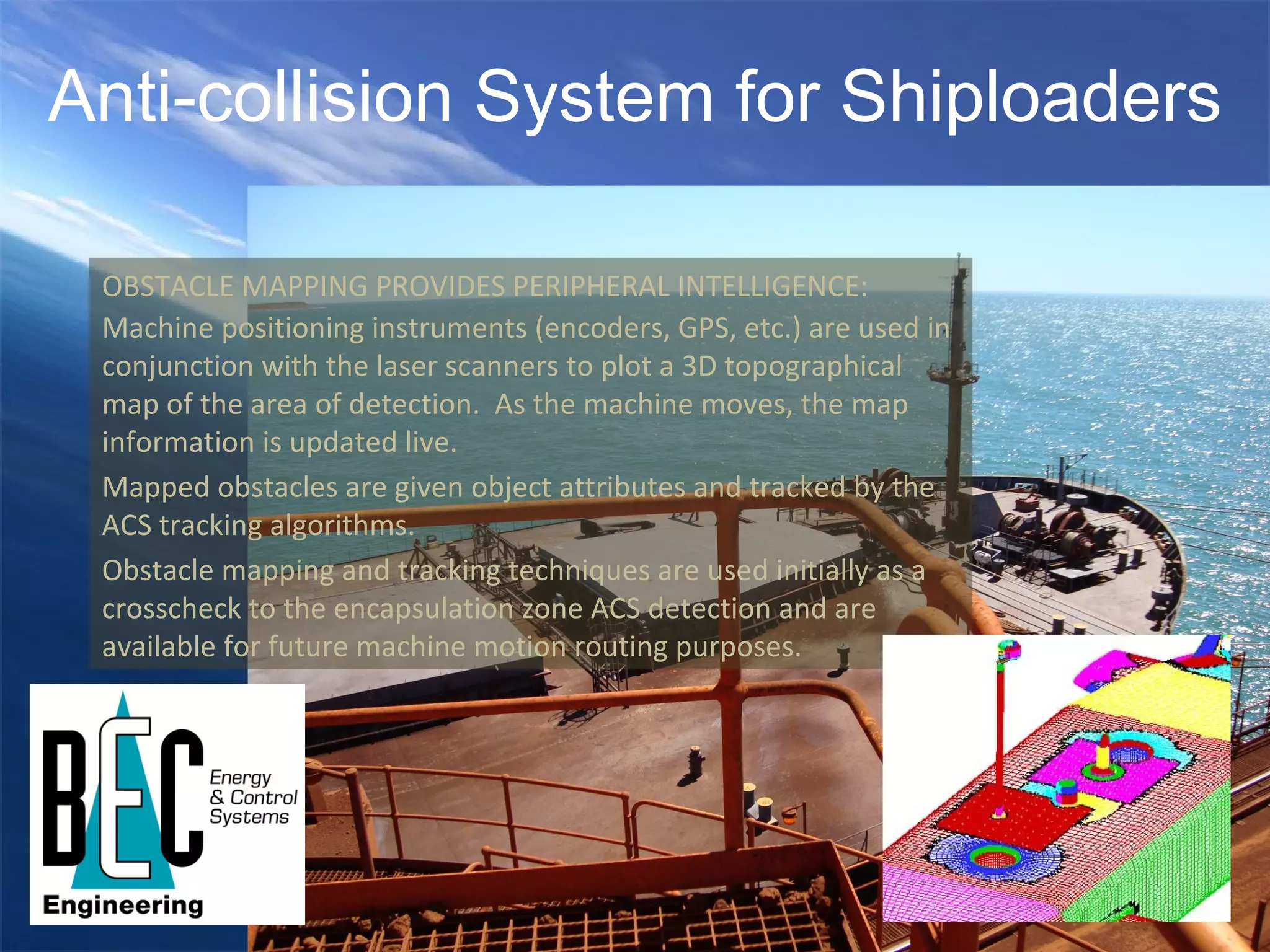
3) Use multi-plane laser scanners and obstacle mapping to create a safety zone around the boom and restrict motion if obstacles are detected.
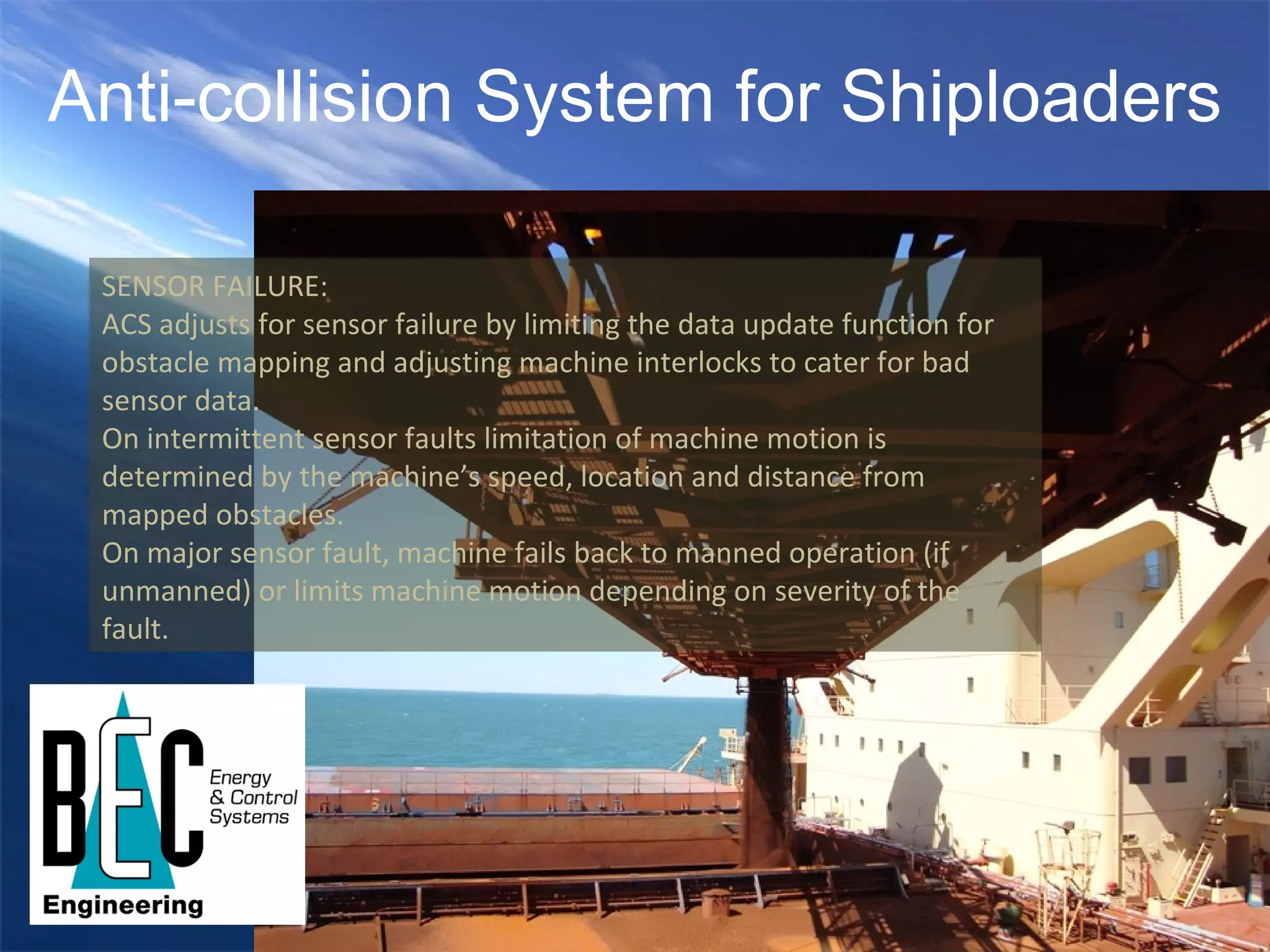
4) Monitor obstacles on the ship and wharf and account for sensor failures to safely operate the shiploader.