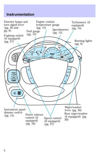
The document provides information about instrumentation, controls, and features for a vehicle. It includes descriptions and illustrations of the instrument cluster, warning lights, gauges, switches, mirrors, climate controls, audio system, and other interior components. Instructions are provided for starting the vehicle, driving, parking brake operation, and safety belt usage. Maintenance and repair information is also included.

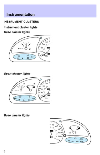
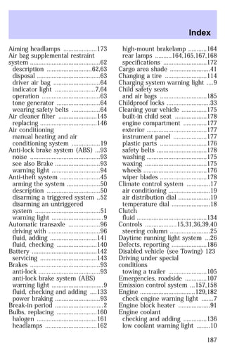
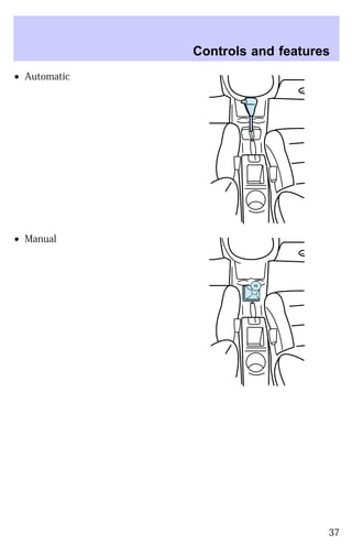
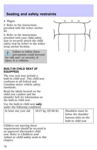
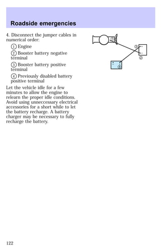
![Sport cluster lights
40
30
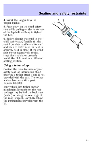
20
140
110 20
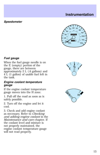
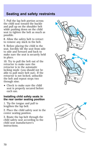
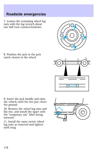
E F C H
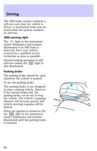
BRAKE
Low fuel
Illuminates when the fuel tank is
almost empty (approximately 8
liters [2 gallons] remain). The
lights will also briefly illuminate
when the ignition key is turned to
ON and the engine is off.
Service engine soon
Illuminates when the engine’s
emissions control system requires
service. The light will also
illuminate, and will remain
illuminated, when the ignition key
is turned to ON and the engine is
off.
Air bag readiness
Illuminates when the air bag
system requires servicing. The
light will also briefly illuminate
when the ignition key is turned to
ON.
0 0 0 0 0 0
0 0 0 0
MPH
km/h
10
50 60 70
80
90
100
120
40
60
80
100
120
160
180
200
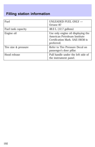
FUEL FILL
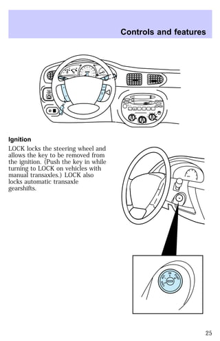
Instrumentation
1/2 2
1
3
4
5
6
7
8
RPM x 1000
SERVICE
ENGINE
SOON
LOW
FUEL
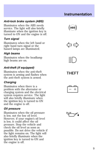
THEFT
ABS
! P
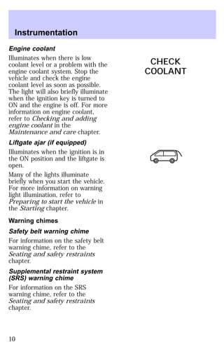
CHECK
COOLANT
LOW
FUEL
SERVICE
ENGINE
SOON
7](https://image.slidesharecdn.com/97escort-140906074536-phpapp01/85/97escort-7-320.jpg)
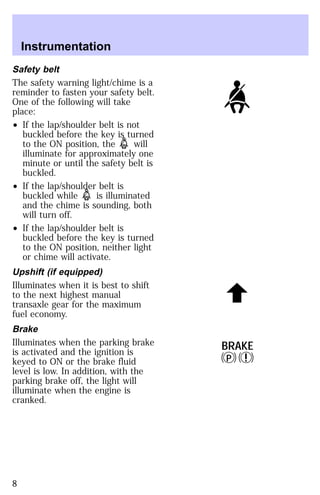
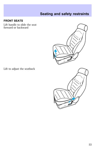
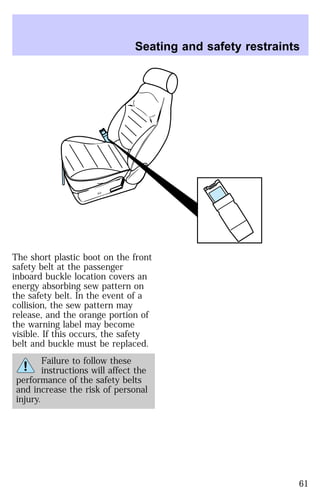
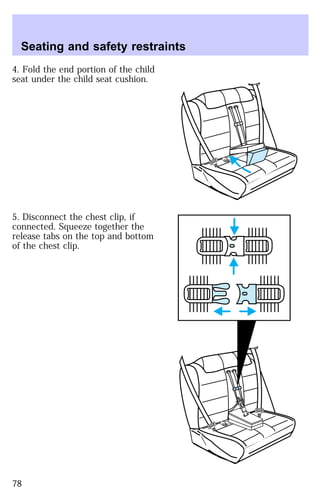
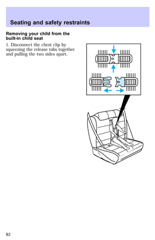
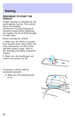
![Seating and safety restraints
in the instrument cluster
illuminates for approximately six
seconds to indicate that the
system is functional.
If you hear a group of five beeps,
or if the warning light does
not illuminate, stays lit, or flashes,
the air bag system requires
immediate service. Have the
vehicle serviced by your dealer.
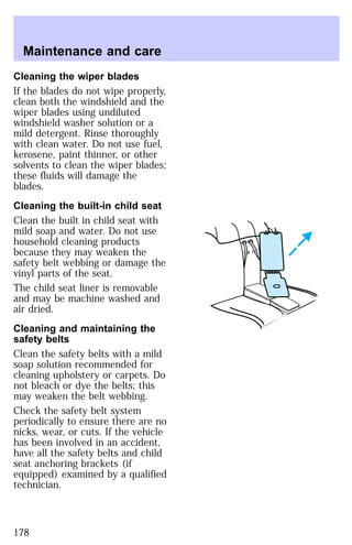
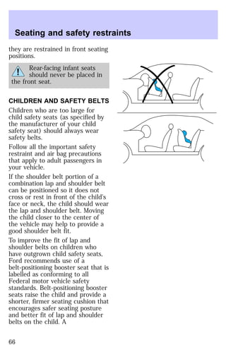
CHILD RESTRAINT
PRECAUTIONS
You are required by law to use
safety restraints for children in the
United States and Canada. If small
children ride in your vehicle
(generally children who are four
years of age or younger and who
weigh 18 kg [40 lb] or less), you
must put them in safety seats
made specially for children. Check
your local and state laws for
specific requirements regarding the
safety of your children.
Never let a passenger hold
a child on his or her lap
while the vehicle is moving. The
passenger cannot protect the
child from injury in a collision.
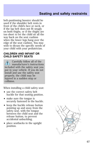
Always follow the instructions and
warnings that come with any infant
or child restraint you might use.
If possible, place children in the
rear seat of your vehicle. Accident
statistics suggest that children are
safer when properly restrained in
rear seating positions than when
65](https://image.slidesharecdn.com/97escort-140906074536-phpapp01/85/97escort-65-320.jpg)
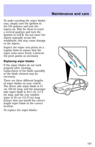
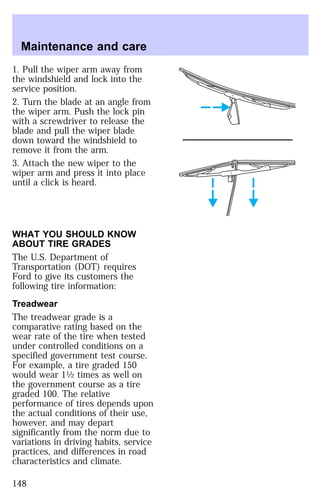
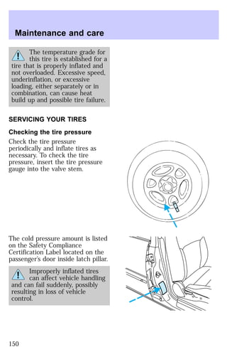
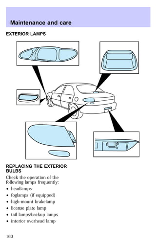
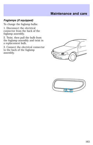
![Maintenance and care
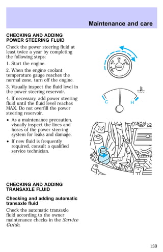
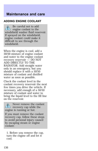
CHECKING AND ADDING
MANUAL TRANSAXLE CLUTCH
FLUID
The brake fluid reservoir and
clutch master cylinder are part of
the same unit; both are refillable
through the brake fluid reservoir
with brake fluid. During normal
operation, the fluid level in the
brake fluid reservoir will rise
slowly. For more information on
brake fluid maintenance, refer to
Checking and adding brake fluid
in this chapter.
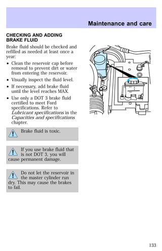
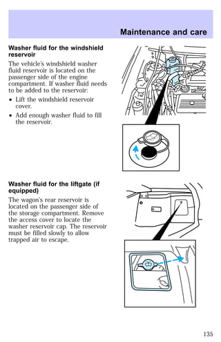
CHECKING AND ADDING
WASHER FLUID
What you should know about
washer fluid
In freezing weather (temperatures
below 0°C [32°F], washer fluid
containing a small amount of
antifreeze is used. State or local
regulations on volatile organic
compounds may restrict the use of
methanol, a common type of
antifreeze. Use a non-methanol
antifreeze in freezing weather only
if the fluid does not damage the
paint finish, wiper blades, or
washer system.
Washer fluid contains
methanol and is poisonous.
Follow all instructions on the
bottle of washer fluid.
134](https://image.slidesharecdn.com/97escort-140906074536-phpapp01/85/97escort-134-320.jpg)
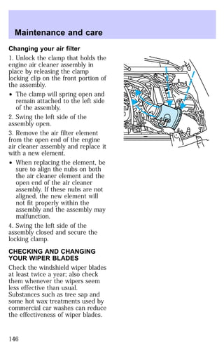
![Maintenance and care
produce coolant which meets Ford
specification ESE-M97B44-A, and
use of such coolant may harm
engine and cooling system
components.
Always dispose of used automotive
fluids in a responsible manner.
Follow your community’s
regulations and standards for
recycling and disposing of
automotive fluids.
Coolant Refill Capacity
To find out how much fluid your
vehicle’s cooling system can hold,
see Refill capacities for fluids in
the Index.
Have your dealer check the engine
cooling system for leaks if you
have to add more than a quart
(liter) of engine coolant per
month.
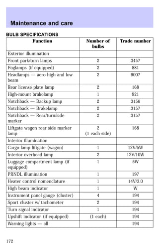
Severe Winter Climate
If you drive in extremely cold
climates (less than -34°F [-36°C]),
it may be necessary to increase the
coolant concentration above 50%.
Refer to the chart on the coolant
container to ensure the coolant
concentration in your vehicle is
such that the coolant will not
freeze at the temperature level in
which you drive during winter
months. Never increase the engine
coolant concentration above 60%.
Leave a 50/50 mixture of engine
coolant and water in your vehicle
year-round in non-extreme
climates.
138](https://image.slidesharecdn.com/97escort-140906074536-phpapp01/85/97escort-138-320.jpg)