Product catlog
•
0 likes•188 views

Product available with Us like CC2500,Serial out color sensor,Serial out analog sensor etc.

Recommended
More Related Content
What's hot
What's hot (20)
Viewers also liked
Viewers also liked (16)
Similar to Product catlog
Similar to Product catlog (20)
Recently uploaded
Recently uploaded (20)
Product catlog
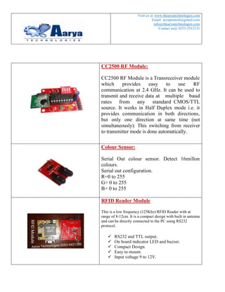
- 1. 1 Visit us @ www.thearyatechnologies.com Email: aryaprotech@gmail.com / info@thearyatechnologies.com Contact us@ 0253-2512131 Wireless Serial Communication RF Modem, 2.4 GHz, 30 meter range Overview CC2500 RF Module is a Transreceiver module which provides easy to use RF communication at 2.4 GHz. It can be used to transmit and receive data at multiple baud rates from any standard CMOS/TTL source. It works in Half Duplex mode i.e. it provides communication in both directions, but only one direction at same time (not simultaneously). This switching from receiver to transmitter mode is done automatically. RF Module can be used for applications that need two way wireless data transmission. It features high data rate and longer transmission distance. The communication protocol is self controlled and completely transparent to user interface. The module can be embedded to your current design so that wireless communication can be set up easily.
- 2. 2 Features Supports Multiple Baud rates (4800/9600/19200/38400). Supports Multiple Channel Selection (CH0/CH1/CH2/CH3). Works on ISM band (2.4 GHz) which is reserved internationally so no need to apply for license. No complex wireless connection software or intimate knowledge of RF is required to connect your serial devices. Designed to be as easy to use as cables. No external Antenna required. Plug and play device. Works on 5-9v DC supply. Standard UART Interface. Applications Consumer electronics. Wireless game controllers. Wireless keyboard and mouse. Weather stations. Sensor Networks / Data collection. Wireless metering. RF enabled remote controls. Access control / Identity discrimination. Wireless data link (communication). Wireless audio. IT home appliance. Smart house products / Security Systems. Remote control / Remote measurement system.
- 3. 3 Specifications Parameter Min Typ Max Units Working Voltage 4.5 5 9 Volts Frequency 2.4 GHz Range 30 Meters UART baud rate (8 bit data, no parity, 1 stop bit) (1) 4800/9600/19200/38400 bps Frequency channel (1) CH0/CH1/CH2/CH3 - Maximum Data Transmission (2) 32 Characters Note: 1. Baud Rate & Frequency Channel Settings depends on DIP Switch Position. (Refer Page No. 5 &6) 2. Carriage Return (CR) is required at the end of string for successful data transmission.
- 4. 4 Pin Diagram Pin Pin Name Pin Name RX Receive Input Input serial data of 3 to 5V logic level TX Transmit Output Output serial data of 3V logic level +5V Power Supply Regulated 5V supply input Gnd Ground Ground level of power supply Operation This module works in half-duplex mode. Means it can either transmit or receive but not both at same time. After each transmission, module will be switched to receiver mode automatically. The LED for TX and RX indicates whether IC is currently receiving or transmitting data. The data sent is checked for CRC error if any. The RX LED is directly on TX OUT pin to indicate that actual data is received and it is sent to output pin. Settings The module supports multiple baud rates and multiple frequency channels. The settings will take place only during power on i.e. you will have to restart the module every time you change the setting. Modifying during power up will have no effect on operation of module. DIP switch number 1 & 2 are used to set the baud rate whereas DIP switch number 3 & 4 are used to select channel frequency.
- 5. 5 Frequency Channel Setting Setting Frequency Channel can be used to have multiple sets operating at same time but without Interfering with each other. The pair having same Channel setting will be able to communicate with each other. Thus avoiding data collision between multiple set of modules. Frequency channel has to be set when module is OFF, as the switch positions are read only during power up. Modifying this setting during operation will have no effect on operation of module. Channel settings mentioned in table given below are for Baud rate 9600 bps. Switch Channel Setting Channel =0 Channel =1 Channel =2 Channel =3
- 6. 6 Baud Rate Setting Baud rate has to be set when module is OFF, as the switch positions are read only during power up. Modifying this setting during operation will have no effect on operation of module. Baud rate settings mentioned in table given below are for Channel 0. Switch Baud Rate Setting 9600 bps 38400 bps 19200 bps 4800 bps
- 7. 7 Interfacing with 8051 Microcontroller
- 8. 8 Code LCD will display data received & send string “received” as an acknowledgement. Here baud rate setting is 9600. #include<reg52.h> #include <string.h> #define cmdport P2 #define dataport P0 unsigned char ntc[32]; unsigned char current_byte = 0; unsigned char icnt = 0; sbit rs = cmdport^6; //register select pin //sbit rw = cmdport^1; // read write pin sbit e = cmdport^7; //enable pin void ser_init(void); void Delay250us (void); void MsDelay (int n); void read_ntc(void); void lcdcmd(unsigned char item); void lcddata(unsigned char item); void lcdstr(unsigned char *s); void lcdinit(void); void Delay250us (void) { int j ; for(j = 0 ; j < 100 ; j ++) { } } void MsDelay (int n) { int j ; for(j = 0 ; j < n ; j ++) { Delay250us() ; Delay250us() ; Delay250us() ; Delay250us() ; } } void ser_init(void) { TMOD=0x20; //Timer 1 Mode 2
- 9. 9 TH1=-3; // Bouad Rate-9600 SCON=0x050; // 8 bit,1 stop bit TR1=1; // start timer ES = 1; // enable serial interrupts } void recieve() interrupt 4 using 1 // Function to recieve data serialy from RS232 { if (RI) { ntc[ current_byte]=SBUF; RI=0; current_byte++; } } void Ser_Write_Text(unsigned char *str) { unsigned char l,i; l = strlen(str)+1; // get the length of string for(i=1;i<l;i++) { SBUF=*str; // send every char one by one while(TI==0); TI=0; str++; } } void ser_write_no(unsigned int no) { SBUF=no; while(TI==0); TI=0; } void read_ntc(void) // Function to display the received string { unsigned char count; lcdcmd(0x01); MsDelay(10); lcdcmd(0x80); MsDelay(10); for(count=0;count<current_byte;count++) { lcddata(ntc[count]);
- 10. 10 if (count==15) { lcdcmd(0xC0); MsDelay(10); } } current_byte=0; } //Function to send command to LCD void lcdcmd(unsigned char item) { dataport = item; rs= 0; //rw=0; e=1; MsDelay(1); e=0; } //Function to send data to LCD void lcddata(unsigned char item) { dataport = item; rs= 1; //rw=0; e=1; MsDelay(1); e=0; } //Function to display string void lcdstr(unsigned char *s) { unsigned char l,i; l = strlen(s); // get the length of string for(i=1;i<=l;i++) { lcddata(*s); // write every char one by one s++; } } //Function to initialise LCD void lcdinit(void) {
- 11. 11 lcdcmd(0x38); // for using 8-bit 2 row mode of LCD MsDelay(10); lcdcmd(0x0E); // turn display ON for cursor blinking MsDelay(10); lcdcmd(0x01); //clear screen MsDelay(10); lcdcmd(0x06); //display ON MsDelay(10); } void main() { EA = 1; /* enable global interrupts */ lcdinit(); MsDelay(10); lcdcmd(0x80); MsDelay(10); lcdstr("CC2500"); lcdcmd(0xC0); MsDelay(10); lcdstr("Interface"); MsDelay(100); ser_init(); MsDelay(50); while(1) { while(current_byte==0); read_ntc(); current_byte=0; Ser_Write_Text("Recieved"); ser_write_no(13); MsDelay(10); } }
- 12. 12 Interfacing with PC Code Code is written inVB.NET 2010 for transmitting & reception of data to & from CC2500 module. Here baud rate setting is 9600 bps.
- 13. 13 Imports System Imports System.IO.Ports Public Class Form1 Dim WithEvents port As SerialPort = New _ System.IO.Ports.SerialPort("COM3", 9600, Parity.None, 8, StopBits.One) Private Sub Form1_Load(ByVal sender As Object, ByVal e As _ System.EventArgs) Handles Me.Load CheckForIllegalCrossThreadCalls = False If port.IsOpen = False Then port.Open() End Sub Private Sub port_DataReceived(ByVal sender As Object, ByVal e As _ System.IO.Ports.SerialDataReceivedEventArgs) Handles port.DataReceived Label1.Text = port.ReadExisting End Sub Private Sub Button1_Click(ByVal sender As System.Object, ByVal e As System.EventArgs) Handles Button1.Click port.Write(TextBox1.Text & vbCr) End Sub Private Sub Button2_Click(ByVal sender As System.Object, ByVal e As System.EventArgs) Handles Button2.Click Application.Exit() End Sub End Class