This document discusses serial communication using an 8051 microcontroller. It covers serial data reception, sample programs, the importance of the RI flag, and interfacing an 8051 to RS232. Specifically:
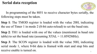
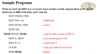
1) It outlines the steps to receive character bytes serially using an 8051, including setting registers like TMOD, TH1, and SCON to configure the baud rate and serial mode.
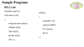
2) It provides an assembly language and C sample program to receive bytes serially and store them in port 1 at 4800 baud.
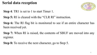
3) It explains that the RI flag indicates when a full character has been received, and must be cleared to allow the next character to be received.
4)