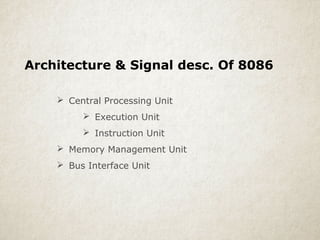
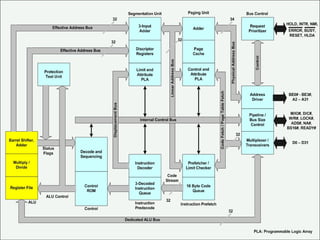
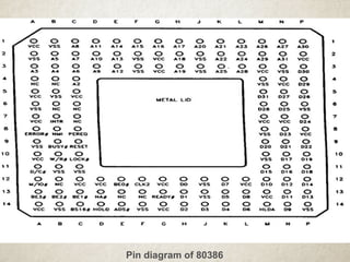
CPU Architecture & Addressing Modes of 8086 Microprocessor
1.
2. Central Processing Unit
Execution Unit
Instruction Unit
Memory Management Unit
Bus Interface Unit
Architecture & Signal desc. Of 8086
3. • map out your table(s) on paper first
• figure out how many rows and columns
• determine the width (600 pixels is standard)
• keeping your table simple at first helps
• look for ideas on the internet (sample), save
the page, and then view it in Dreamweaver.
Creating Tables:
4. Execution unit & Instr Unit
The EU has 8 general purpose and 8 special purpose
registers, used for handling data or calculating offset
addresses.
The IU decodes the opcode bytes received from 16-byte
instr code queue and arranges them into a 3-instr
decoded-instr queue, after decoding them so as to pass it
to the control section for deriving the necessary control
signals.
5. The Memory Management unit (MMU)
Segmentation Unit
It allows the use of two address components, Segment and Offset
for relocability and sharing of code and data
Max. 4 Gb segments
Paging Unit
It organizes the phy. Memory in terms of pages of 4 Kb size each.
It works under the control of segmentation unit
6. Bus control Unit
It controls the access of the bus
It has a prioritizer to resolve the priority of the
various bus requests.
The address driver drives the bus enable and
address signals A0-A31
The pipeline and dynamic bus sizing units handle the related
control signals
The Data buffers interface the internal data bus with the system
bus
8. NA – Next address input pin, if activated, allows
address pipeling, during 80386 bus cycles
Busy – The busy input signal indicates to the
CPU that the coprocessor is busy with the
alloted task.
PEREQ – The processor extension request
output indicates to the cpu to fetch a data word
for the coprocessor
9. 11 addressing modes to facilitate efficient execution of
higher level language programs.
In case of all those modes, the 80386 can now have 32-
bit immediate or 32- bit register operands or
displacements.
It has a family of scaled modes. In case of scaled modes,
any of the index register values can be multiplied by a
valid scale factor to obtain the displacement
The valid scale factor are 1, 2, 4 and 8.
ADDRESSING MODES
10. The different scaled modes are as follows.
•Scaled Indexed Mode: Contents of the an index
register are multiplied by a scale factor that may be
added further to get the operand offset.
•Based Scaled Indexed Mode: Contents of the an
index register are multiplied by a scale factor and then
added to base register to obtain the offset.
•Based Scaled Indexed Mode with
Displacement: The Contents of the an index
register are multiplied by a scaling factor and the
result is added to a base register and a displacement
to get the offset of an operand.