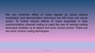
This document discusses error handling techniques for data communication. It describes two main error control coding techniques:
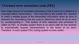
1. Forward error correction (FEC) adds redundancy to messages to enable error detection and correction. It is useful for systems without return paths for retransmission.
2. Automatic repeat request (ARQ) adds small amounts of redundancy to detect errors, then ignores erroneous messages or requests retransmission. It is more reliable than FEC and is used for duplex systems with two-way communication links.
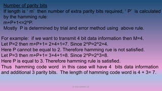
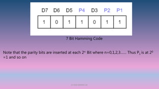
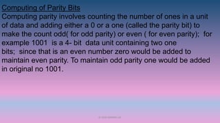
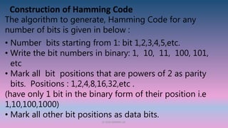
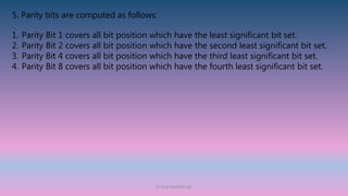
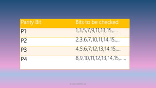
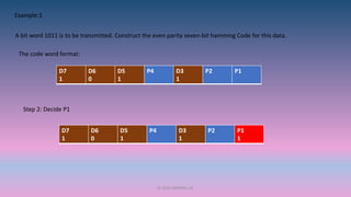
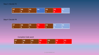
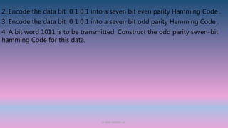
The document then focuses on Hamming codes as a common type of FEC. Hamming codes add parity bits to messages according to rules to enable location and correction of errors at the receiver. Examples are provided of constructing 7