Download to read offline

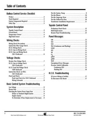
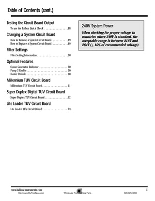
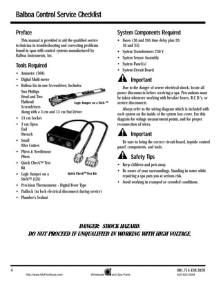
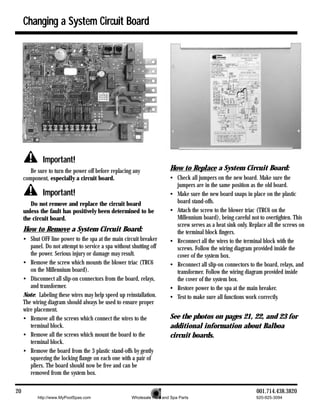
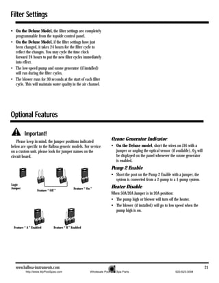
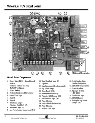
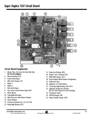


This document provides instructions for troubleshooting Balboa control systems for pools and spas. It describes key system components like the topside control panel, circuit board, temperature and high-limit sensors. It provides steps for checking wiring, voltages, and troubleshooting common issues like low voltage, blown fuses, and error messages. Safety tips are included to avoid shock when working with high voltage equipment.