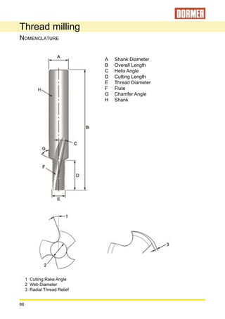
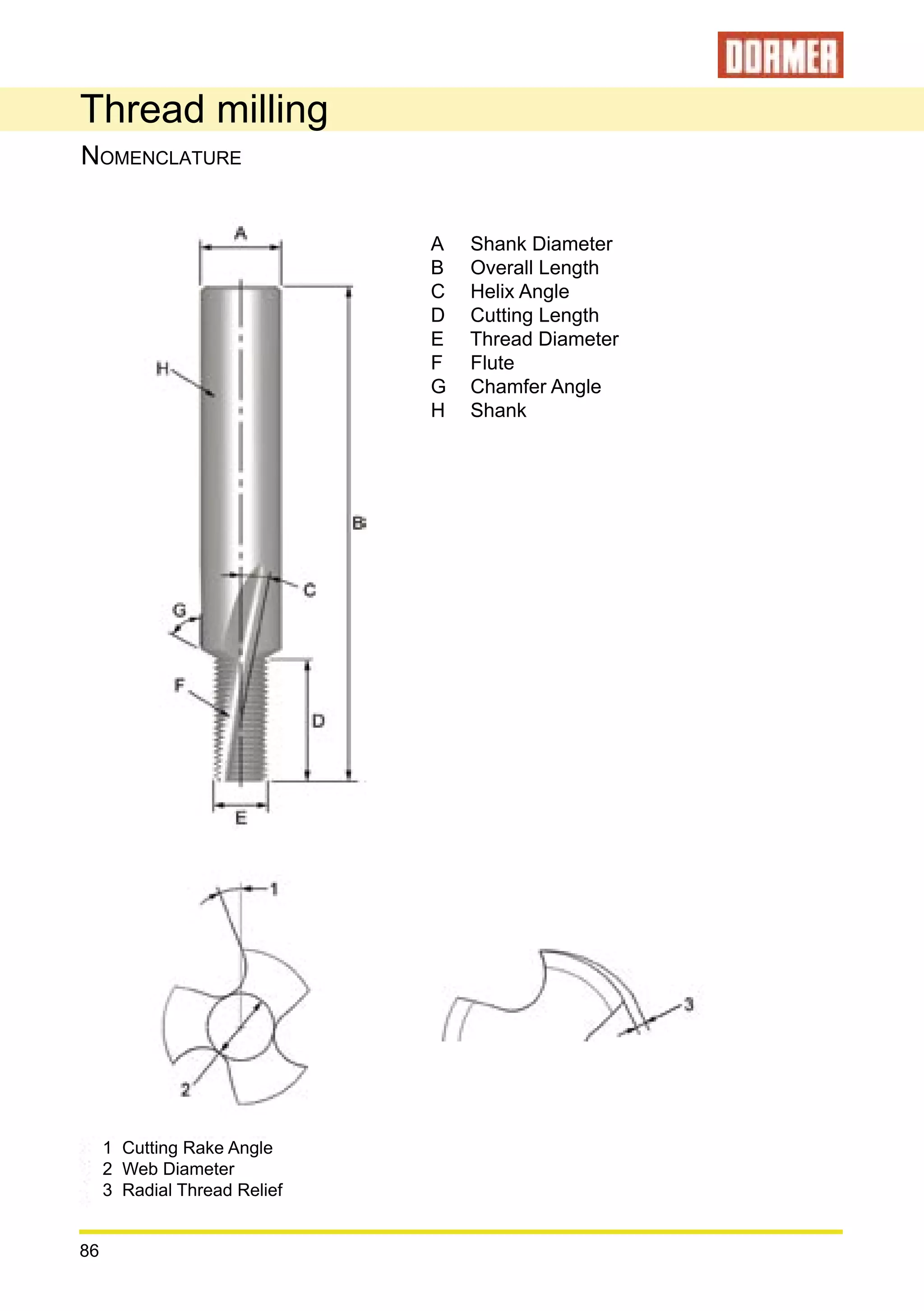
1. Thread milling is a method of producing threads using a milling cutter that can move in helical paths to cut threads.
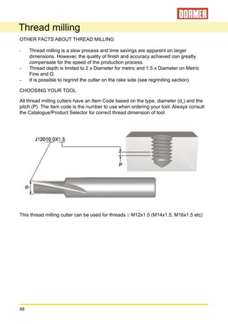
2. Selecting the proper thread milling cutter for the application from the product selector will provide cutting data and an optimized CNC program.
3. Thread milling offers advantages over conventional threading like smaller chips, tolerance adjustments via calculations, longer tool life, and suitability for most materials.