SlideShare a Scribd company logo
1 of 26
Download to read offline
1/26
Applications Library
Note: The descriptions that follow offer links allowing access to the corresponding
application.
If Zelio Soft 2 software is installed, a click on the link will open the program. You may then
select simulation mode (1) and start the module (RUN) (2).
(1)
(2)
Floating pop-ups are available to change and view the input-output status. To view them or
mask them, use the icon bar at the bottom of the screen:
1 Applications in Ladder language
1.1 GREENHOUSE AUTOMATIC VENTILATION PANE CONTROL
Specifications:
The owner of a greenhouse would like to acquire an installation to manage the opening
and closing of the ventilation window panes located on the greenhouse roof.
The greenhouse has two window panes to provide ventilation. The opening of these
window panes is controlled by a motor and 2 sensors that indicate whether the window
panes are open or closed:
During the day, the window panes open to ventilate the structure from 12:00 to 15:00, at
the time of day when, in principle, the temperature is the highest. However, if the
temperature is less than 10°C, the window panes do not open, or when they are already
open, they close.
In addition, the window panes open during the day when the temperature reaches 25°C. If
the temperature falls below 25 °C, the window panes must close again.
Finally, at night, the window panes remain closed regardless of the temperature.
Power by http://www.hackspedia.com
2/26
Summary diagram:
Description of the inputs/ouputs:
INPUTS: OUTPUTS:
I1 Opened window sensor Q1 Opening of the window panes
I2 Closed window sensor Q2 Closing of the window panes
IB Temperature (analog input)
The temperature is supplied by a sensor with output voltage of 0 to 10 V.
Model Required:
Zelio Logic with clock and analog inputs.
SR2 B121 BD (24 V DC) ou SR2 B121 JD (12 V DC) par exemple.
Program Description:
3 time ranges are used:
-Range 1: Night, from 21:00 to 07:00
-Range 2: Daytime, from 7:00 to 12:00 a.m. and from 3:00 to 9:00 p.m.
-Range 3: Noon, from 12:00 to 15:00
Power by http://www.hackspedia.com
3/26
Logic diagram:
Click on the link below to access the application:
Greenhouse automatic ventilation pane control (ladder)
Note: Use the floating pop-up of analog input IB to vary the temperature. To call it up, click
on the corresponding icon in the lower bar.
Power by http://www.hackspedia.com
4/26
1.2 INDOOR/OUTDOOR LIGHTING OF A HOME
Specifications:
A homeowner would like to install a system capable of controlling the lighting of a stairway
and outdoor entrance providing access to the home.
Outdoor Lighting: The circuit is activated at night by a twilight switch. A sensor detects any
passage and activates the outdoor lighting for 2 minutes.
Indoor lighting: Two push-buttons are situated in the stairwell: one in the entrance, the
other at the top of the stairs. Their function is identical. Time-delayed (2 minutes) lighting is
obtained by quickly pressing one of the buttons.
Description of the inputs/ouputs:
INPUTS: OUTPUTS:
I1 Passage sensor Q1 Outdoor lighting
I2 Twilight switch Q2 Indoor lighting
I3 Pushbutton
I4 Pushbutton
Model Required:
No specific condition:
SR2 B121 BD (24 VDC) for example.
Logic diagram:
Click on the link below to access the application:
Indoor/Outdoor lightning of a home
Power by http://www.hackspedia.com
5/26
1.3 ACCESS CONTROL, AUTOMATIC GATE
Specifications:
A homeowner wants access to his residence to be controlled by an automatic gate
equipped with a dual direction (opening and closure) motor.
Opening: Whether the gate is closed or in an intermediate position, the remote control
signal causes the full opening of the gate. During the opening process, any new action on
the remote control stops or restarts the motor.
As soon as the gate is fully open, a 4-second time delay delays its closure.
Closure: During the closing process, if the remote control is activated or if the sensor
detects a passage, the gate is opened. As long as the sensor is activated, (vehicle
stopped in the passage way for example), the gate remains fully open.
Description of the inputs/ouputs:
INPUTS: OUTPUTS:
I1 Remote control Q1 Gate opening
I2 Gate closed position Q2 Gate closure
I3 Gate closed position
I4 Passage sensor
Model Required:
No specific condition.
SR2 B121 BD (24 V DC) or SR2 B121 JD (12 V DC) for example.
Advantages of the application:
The safety feature of being able to stop gate opening or closing via the remote control
signal is an essential advantage for this type of application.
Power by http://www.hackspedia.com
6/26
Logic diagram:
Click on the link below to access the application:
Access control, automatic gate
Power by http://www.hackspedia.com
7/26
1.4 UNDERGROUND CAR PARK CONTROL
Specifications:
We want to complete and centralize the control of the underground car park of an
administration building.
Vehicle entrance/exit control: access is allowed by an automatic barrier. Users can access
the car park during business hours: Monday through Friday from 8:30 a.m. to 5:30 p.m.,
Saturday from 9:30 to noon. However, it is possible to manually inhibit the blocking of the
barrier by pressing on Z4 (function restored by pressing on Z2) in case of an exceptional
event.
Counting: The car park capacity is limited to 93 vehicles. A counter will block access to the
car park if it is full and will control a light panel indicating ‘’Car park Full’’. It is also possible
to manually increase or decrease (in increments) the number of vehicles present in the car
park (using Z1 and Z3).
CO2 level: For safety reasons, a CO2 sensor indicates when the level is high and controls
the operation of a fan (10 minutes).
Light: The lighting switches on for 2 minutes each time a vehicle enters the car park or
whenever a pedestrian presses the switch. .
Description of the inputs/ouputs:
INPUTS: OUTPUTS:
I1 Vehicle entry Q1 Indicates when the car park is full.
I2 Vehicle exit Q2 Locks the entry barrier
I3,I4 Pushbuttons at pedestrian access
points
Q3 Lightning
IB Carbon dioxide level sensor Q4 Fan control
Z1 Manually increments the number of
vehicles
Z2 Resumes automatic entry control
Z3 Manually decrements the number of
vehicles
Z4 Manual release of entry barrier
Model Required:
Model with clock and analog inputs.
SR2 B121 BD (24 V DC) or SR2 B121 JD (12 V DC) for example.
Advantages of the application:
Full car park control using a single logic module.
Note: Use the floating pop-ups to simulate the variation of the level of CO2 (analog input
IB) and to use the push-buttons. To call them up, click on the corresponding icons in the
lower bar.
Power by http://www.hackspedia.com
8/26
Logic diagram:
Click on the link below to access the application:
Underground car park control
Power by http://www.hackspedia.com
9/26
1.5 ROOM TEMPERATURE REGULATION
Specifications:
The ambient temperature of a room is controlled in the heat mode by a heater and a fan,
and in the chill mode only by the fan. A heat sensor provides a 0-10 V signal.
A switch is used to deactivate temperature regulation.
The direct evolution of inputs and outputs can be monitored in a supervision window.
Description of the inputs/ouputs:
INPUTS: OUTPUTS:
I1 On/Off switch Q1 Heater
I2 Mode selection Q2 Fan
IB Ambient temperature (analog input)
IC Setpoint (analog input)
The temperature is supplied by a sensor with output voltage of 0 to 10 V.
Model Required:
Zelio Logic with analog inputs.
SR2 B121 BD (24 V DC) or SR2 B121 JD (12 V DC) for example.
Program Description:
Input I1 =0 : regulation is off.
Input I1 =1 : Regulation is on.
Input I2 =0 : chill mode.
Input I2 =1 : heat mode.
Hysteresis:
Advantages of the application:
Use of 0-10 V analog inputs.
The supervision window.
Power by http://www.hackspedia.com
10/26
Logic diagram:
Power by http://www.hackspedia.com
11/26
Supervision window:
Click on the link below to access the application:
Room temperature regulation
Note: to simulate this program, first adjust the setpoint using analog input IC then switch
on the temperature regulation (I1=1, click on I1). If the chill mode is selected (I2=0), the fan
will be activated as soon as the temperature exceeds the setpoint of 3°C and will stop
when it drops 2°C below the setpoint. And conversely for the heat mode.
Power by http://www.hackspedia.com
12/26
1.6 PROGRESSIVE HEATING OF BOILER ELEMENTS
Specifications:
To avoid over-consumption on boiler start-up, the heating elements are heated
progressively, and stopped progressively when the boiler is stopped.
This operating principle is shown by the following timing diagram:
An “On” (MA) button authorizes the activation of the first heating element (S1). After a
time-delay T, the second element (S2) starts up. After the same time-delay, the third
elements starts up (S3), then the fourth element (S4) again after time-delay T. An “Off”
(AR) button deactivates S1. The three other elements are progressively deactivated after
time-delay T with each deactivation of the preceding element.
Description of the inputs/ouputs:
INPUTS: OUTPUTS:
I1 On button Q1 First heating element S1
I2 Off button Q2 Second heating element S2
Q3 Third heating element S3
Q4 Fourth heating element S4
Model Required:
No specific condition:
SR2 B121 BD (24 V DC) or SR2 B121 JD (12 V DC) for example.
Program Description:
In principle, time delay T is identical for the activation/deactivation of all the heating
elements. The program includes three TIMER function blocks. The function to perform
according to the specifications requires entering the same time-delay value in the three
blocks.
As a result, if the user wants to modify one of them, he/she will have to enter the new
selection in the three blocks.
Power by http://www.hackspedia.com
13/26
Logic diagram:
Click on the link below to access the application:
Boiler elements
Power by http://www.hackspedia.com
14/26
2 Applications in FBD language
2.1 GREENHOUSE AUTOMATIC VENTILATION PANE CONTROL
Specifications:
The owner of a greenhouse would like to acquire an installation to manage the opening
and closing of the ventilation window panes located on the greenhouse roof.
The greenhouse has two window panes to provide ventilation. The opening of these
window panes is controlled by a motor and 2 sensors that indicate whether the window
panes are open or closed:
During the day, the window panes open to ventilate the structure from 12:00 to 15:00, at
the time of day when, in principle, the temperature is the highest. However, if the
temperature is less than 10°C, the window panes do not open, or when they are already
open, they close.
In addition, the window panes open during the day when the temperature reaches 25°C. If
the temperature falls below 25 °C, the window panes must close again.
Finally, at night, the window panes remain closed regardless of the temperature.
Summary diagram:
Description of the inputs/ouputs:
INPUTS: OUTPUTS:
I1 Opened window sensor Q1 Opening of the window panes
I2 Closed window sensor Q2 Closing of the window panes
IB Temperature (analog input)
The temperature is supplied by a sensor with output voltage of 0 to 10 V.
Model Required:
Power by http://www.hackspedia.com
15/26
Zelio Logic with clock and analog inputs.
SR2 B121 BD (24 V DC) or SR2 B121 JD (12 V DC) for example.
Program Description:
3 time ranges are used:
-Range 1: Night, from 21:00 to 07:00 (B13)
-Range 2: Daytime, from 7:00 a.m. to 12:00 p.m. and from 3:00 to 9:00 p.m. (B12)
-Range 3: Noon, from 12:00 to 15:00 (B11)
Advantages of the application:
The programmable logic function is used simplifying the diagram
Logic diagram:
Click on the link below to access the application:
Greenhouse automatic ventilation pane control (FBD)
Power by http://www.hackspedia.com
16/26
2.2 INDOOR/OUTDOOR LIGHTING OF A HOME
Specifications:
A homeowner would like to install a system capable of controlling the lighting of a stairway
and outdoor entrance providing access to the home.
Outdoor lighting: The circuit is activated every year from June 1st to October 1st and at
night by a twilight switch. A sensor detects any passage and activates the outdoor lighting
for 2 minutes.
Indoor lighting: Two pushbuttons are situated in the stairwell; one in the entrance, the
other at the top of the stairs. Their function is identical.
• Time-delayed (30 seconds) lighting is obtained by quickly pressing one of the buttons.
The timer can be inhibited by renewed action on one of the buttons.
• Permanent lighting is activated if one button is depressed for at least 2 seconds. A quick
press stops it.
Table of inputs/outputs:
INPUTS: OUTPUTS:
I1 Passage sensor Q1 Outdoor lighting
I2 Twilight switch Q4 Indoor lighting
I3 Pushbutton
I4 Pushbutton
Model Required:
Zelio Logic with clock:
SR2 B121 BD (24 VDC) for example.
Program Description:
Programming is possible at two levels.
Level 1 : Program satisfying the specifications.
Level 2: Use of SFC/Grafcet functions
Advantages of the application:
It is possible to handle the application with sequential functions.
Power by http://www.hackspedia.com
17/26
Logic diagram Level 1:
Click on the link below to access the application:
Indoor/Outdoor lightning of a home - level 1
Power by http://www.hackspedia.com
18/26
Logic diagram Level 2 (SFC/Grafcet) :
Click on the link below to access the application:
Indoor/Outdoor lightning of a home - level 2 (SFC-Grafcet)
Power by http://www.hackspedia.com
19/26
2.3 ACCESS CONTROL, AUTOMATIC GATE
Specifications:
A homeowner wants access to his residence to be controlled by an automatic gate
equipped with a dual direction (opening and closure) motor.
Opening: Whether the gate is closed or in an intermediate position, the remote control
signal causes the full opening of the gate. During the opening process, each new action on
the remote control stops or restarts the motor.
As soon as the gate is fully open, a 4-second time delay delays its closure.
Closure: During the closing process, if the remote control is activated or if the sensor
detects a passage, the gate is opened. As long as the sensor is activated, (vehicle
stopped in the passage way for example), the gate remains fully open.
Description of the inputs/ouputs:
INPUTS: OUTPUTS:
I1 Remote control Q1 Gate opening
I2 Gate closed position Q2 Gate closure
I3 Gate closed position
I4 Passage sensor
Model Required:
No specific condition.
SR2 B121 BD (24 V DC) or SR2 B121 JD (12 V DC) for example.
Program Description:
The T1 timer (A-C Timer A-C) is used to switch the motor in the opening direction 0.5
seconds after the inhibition of closure. This avoids any short-circuit and mechanical jerk.
Timer T2 (A-C Timer) fulfills two simultaneous functions. The 4-second triggering delay
maintains the gate in the open position before beginning to closing motion.. The 0.2
second triggering delay allows the activation conditions of the ‘’AND’’ logic block output to
be verified.
Advantages of the application:
The safety feature of being able to stop gate opening or closing via the remote control
signal is an essential advantage for this type of application.
The parallel connection to the motor terminals allows the addition of a light signal
indicating any movement of the gate.
Power by http://www.hackspedia.com
20/26
Logic diagram:
Click on the link below to access the application:
Access control, automatic gate
Power by http://www.hackspedia.com
21/26
2.4 ROOM TEMPERATURE REGULATION
Specifications:
The ambient temperature of a room is controlled in the heat mode by a heater and a fan,
and in the chill mode only by the fan. A temperature sensor, via a converter, provides a 0-
10V signal. A switch is used to deactivate temperature regulation.
Screen display:
The heat or chill mode is displayed
The ambient temperature and setpoint are displayed.
A trigger function is provided to set up regulation that takes into account a hysteresis of
+2°C from start to stop and –3°C from stop to start.
Description of the inputs/ouputs:
INPUTS: OUTPUTS:
I1 On/Off switch Q1 Heater
I2 Mode selection Q4 Fan
IB Ambient temperature (analog input)
IC Setpoint (analog input)
The temperature is supplied by a sensor with output voltage of 0 to 10 V.
Model Required:
Zelio Logic with analog inputs.
SR2 B121 BD (24 V DC) or SR2 B121 JD (12 V DC) for example.
Program Description:
Input I1 =0 : regulation is off.
Display example:
***********
OFF
***********
0017.2
InputI1 =1 : Regulation is on.
Display example:
heat mode.
0020.0 (setpoint display)
0017.2 (temperature display)
Power by http://www.hackspedia.com
22/26
Hysteresis:
Advantages of the application:
Use of 0-10 V analog inputs.
Logic diagram:
Note 1: When the module is on, select FBD DISPLAY in the main menu of the module to
view the active text blocks on the screen. In a simulation, it is possible to call up the front
panel by selecting 3 Front Panel in the Window menu.
Note 2: It will probably be necessary to wire additional gain functions after inputs IB and
IC.
Click on the link below to access the application:
Room temperature regulation
Power by http://www.hackspedia.com
23/26
2.5 PROGRESSIVE HEATING OF BOILER ELEMENTS
Specifications:
To avoid over-consumption on boiler start-up, the heating elements are heated
progressively, and stopped progressively when the boiler is stopped.
This operating principle is shown by the following timing diagram:
An “On” (MA) button authorizes the activation of the first heating element (S1). After a time
delay T, the second element (S2) starts up. After the same time-delay, the third elements
starts up (S3), then the fourth element (S4) again after time-delay T. An “Off” (AR) button
deactivates S1. The three other elements are progressively deactivated after time-delay T
with each deactivation of the preceding element.
Description of the inputs/ouputs:
INPUTS: OUTPUTS:
I1 On button Q1 First heating element S1
I2 Off button Q2 Second heating element S2
Q3 Third heating element S3
Q4 Fourth heating element S4
Model Required:
No specific condition.
SR2 B121 BD (24 V DC) or SR2 B121 JD (12 V DC) for example.
Program Description:
In principle, time delay T is identical for the activation/deactivation of all the heating
elements. The program includes three TIMER function blocks. The function to perform
according to the specifications requires entering the same time-delay value in the three
blocks.
As a result, if the user wants to modify one of them, he/she will have to enter the new
selection in the three blocks.
Power by http://www.hackspedia.com
24/26
Logic diagram:
Click on the link below to access the application:
Progressive heating of boiler elements
Power by http://www.hackspedia.com
25/26
2.6 SCHOOL BELL
Specifications:
A high school wants to control the daily bell and alarm system using the same device. The
bell rings from Monday to Friday for one minute except during the holidays. The “alarm”
mode is active during the holidays, on weekends, and at night Monday through Friday.
The alert is given for 1 minute by an audio signal alternating 2 s ON, 1 s OFF, and by an
indicator light activated by a motion detector.
It must be possible to reset the alarm.
Advantages of the application:
The annual clock, available on FBD, allows school holidays and legal holidays to be taken
into account.
Description of the inputs/ouputs:
INPUTS: OUTPUTS:
I1 Alarm : On/off Q1 Ringing
I2 Motion detector Q2 Indicator light
I3 Alarm: Reset
Model Required:
Model with annual clock:
SR2 B121 BD (24 V DC) or SR2 B121 JD (12 V DC) for example.
Program Description:
To program the three clocks, copy or adapt the parameters of figures 1, 2 and 3.
The logic block unites the activation conditions of the “alarm” mode according to the
equation :
INPUT
1 2 3 4 OUTPUT
Time 2 I1 I2 Time 3
0 1 1 1 1
Figure 1:
Power by http://www.hackspedia.com
26/26
Figure 2:
Figure 3:
Logic diagram:
Click on the link below to access the application:
School bell
Power by http://www.hackspedia.com

More Related Content

What's hot

Temperature Controller
Temperature ControllerTemperature Controller
Temperature ControllerSupriya Gorai
 
Advanced motion controls dq111ee30a80lac
Advanced motion controls dq111ee30a80lacAdvanced motion controls dq111ee30a80lac
Advanced motion controls dq111ee30a80lacElectromate
 
Microprocessor-Based Automatic Door Opener
Microprocessor-Based Automatic Door OpenerMicroprocessor-Based Automatic Door Opener
Microprocessor-Based Automatic Door OpenerJitendra Choudhary
 
Manual of Thermostat Fan Coil 4Pipes MH8 series - MCO HOME
Manual of Thermostat Fan Coil 4Pipes MH8 series - MCO HOME Manual of Thermostat Fan Coil 4Pipes MH8 series - MCO HOME
Manual of Thermostat Fan Coil 4Pipes MH8 series - MCO HOME Domotica daVinci
 
Z-Wave Keypad Manual - PoPP
Z-Wave Keypad Manual - PoPPZ-Wave Keypad Manual - PoPP
Z-Wave Keypad Manual - PoPPDomotica daVinci
 
Datasheet
DatasheetDatasheet
Datasheetjuan
 
Codigos de averias u (bus comunicaciones)
Codigos de averias u (bus comunicaciones)Codigos de averias u (bus comunicaciones)
Codigos de averias u (bus comunicaciones)negro77lv
 
Automatic room temperature controlled fan using arduino uno microcontroller
Automatic room temperature controlled fan using   arduino uno  microcontrollerAutomatic room temperature controlled fan using   arduino uno  microcontroller
Automatic room temperature controlled fan using arduino uno microcontrollerMohammod Al Emran
 
Automatic DC Fan using LM35 (english version)
Automatic DC Fan using LM35 (english version)Automatic DC Fan using LM35 (english version)
Automatic DC Fan using LM35 (english version)Nurlatifa Haulaini
 
Side Swing Gate Opener Installation Manual
Side Swing Gate Opener Installation ManualSide Swing Gate Opener Installation Manual
Side Swing Gate Opener Installation ManualLeviWu1
 
Sonkor fan coil high wall swc eco elegant presentation slideshare
Sonkor fan coil high wall swc eco elegant presentation slideshareSonkor fan coil high wall swc eco elegant presentation slideshare
Sonkor fan coil high wall swc eco elegant presentation slideshareSonkorGlobal
 
temperature control using 8086 microprocessor by vikas arya
temperature control using 8086 microprocessor by vikas arya temperature control using 8086 microprocessor by vikas arya
temperature control using 8086 microprocessor by vikas arya VIKAS ARYA
 
E5cn omron digital temperature controller
E5cn omron digital temperature controllerE5cn omron digital temperature controller
E5cn omron digital temperature controllersteven qi
 
SIEMENS RWD CONTROLLER SERIES
SIEMENS RWD  CONTROLLER SERIES SIEMENS RWD  CONTROLLER SERIES
SIEMENS RWD CONTROLLER SERIES CONTROLS & SYSTEMS
 
Kjr 29 b (termostato alam. fan coil)
Kjr 29 b (termostato alam. fan coil)Kjr 29 b (termostato alam. fan coil)
Kjr 29 b (termostato alam. fan coil)German Nava
 
AUTOMATIC FAN CONTROLLER USING THERMISTOR
AUTOMATIC FAN CONTROLLER USING THERMISTORAUTOMATIC FAN CONTROLLER USING THERMISTOR
AUTOMATIC FAN CONTROLLER USING THERMISTORPankaj Jagadale
 
Advanced motion controls dq111ee20a8bdc
Advanced motion controls dq111ee20a8bdcAdvanced motion controls dq111ee20a8bdc
Advanced motion controls dq111ee20a8bdcElectromate
 
An introduction to temperature control
An introduction to temperature controlAn introduction to temperature control
An introduction to temperature controlWest Control Solutions
 

What's hot (20)

Temperature Controller
Temperature ControllerTemperature Controller
Temperature Controller
 
Advanced motion controls dq111ee30a80lac
Advanced motion controls dq111ee30a80lacAdvanced motion controls dq111ee30a80lac
Advanced motion controls dq111ee30a80lac
 
PEL_Automation
PEL_AutomationPEL_Automation
PEL_Automation
 
Microprocessor-Based Automatic Door Opener
Microprocessor-Based Automatic Door OpenerMicroprocessor-Based Automatic Door Opener
Microprocessor-Based Automatic Door Opener
 
Manual of Thermostat Fan Coil 4Pipes MH8 series - MCO HOME
Manual of Thermostat Fan Coil 4Pipes MH8 series - MCO HOME Manual of Thermostat Fan Coil 4Pipes MH8 series - MCO HOME
Manual of Thermostat Fan Coil 4Pipes MH8 series - MCO HOME
 
Z-Wave Keypad Manual - PoPP
Z-Wave Keypad Manual - PoPPZ-Wave Keypad Manual - PoPP
Z-Wave Keypad Manual - PoPP
 
Datasheet
DatasheetDatasheet
Datasheet
 
Codigos de averias u (bus comunicaciones)
Codigos de averias u (bus comunicaciones)Codigos de averias u (bus comunicaciones)
Codigos de averias u (bus comunicaciones)
 
Automatic room temperature controlled fan using arduino uno microcontroller
Automatic room temperature controlled fan using   arduino uno  microcontrollerAutomatic room temperature controlled fan using   arduino uno  microcontroller
Automatic room temperature controlled fan using arduino uno microcontroller
 
Automatic DC Fan using LM35 (english version)
Automatic DC Fan using LM35 (english version)Automatic DC Fan using LM35 (english version)
Automatic DC Fan using LM35 (english version)
 
Capston project ITT
Capston project ITTCapston project ITT
Capston project ITT
 
Side Swing Gate Opener Installation Manual
Side Swing Gate Opener Installation ManualSide Swing Gate Opener Installation Manual
Side Swing Gate Opener Installation Manual
 
Sonkor fan coil high wall swc eco elegant presentation slideshare
Sonkor fan coil high wall swc eco elegant presentation slideshareSonkor fan coil high wall swc eco elegant presentation slideshare
Sonkor fan coil high wall swc eco elegant presentation slideshare
 
temperature control using 8086 microprocessor by vikas arya
temperature control using 8086 microprocessor by vikas arya temperature control using 8086 microprocessor by vikas arya
temperature control using 8086 microprocessor by vikas arya
 
E5cn omron digital temperature controller
E5cn omron digital temperature controllerE5cn omron digital temperature controller
E5cn omron digital temperature controller
 
SIEMENS RWD CONTROLLER SERIES
SIEMENS RWD  CONTROLLER SERIES SIEMENS RWD  CONTROLLER SERIES
SIEMENS RWD CONTROLLER SERIES
 
Kjr 29 b (termostato alam. fan coil)
Kjr 29 b (termostato alam. fan coil)Kjr 29 b (termostato alam. fan coil)
Kjr 29 b (termostato alam. fan coil)
 
AUTOMATIC FAN CONTROLLER USING THERMISTOR
AUTOMATIC FAN CONTROLLER USING THERMISTORAUTOMATIC FAN CONTROLLER USING THERMISTOR
AUTOMATIC FAN CONTROLLER USING THERMISTOR
 
Advanced motion controls dq111ee20a8bdc
Advanced motion controls dq111ee20a8bdcAdvanced motion controls dq111ee20a8bdc
Advanced motion controls dq111ee20a8bdc
 
An introduction to temperature control
An introduction to temperature controlAn introduction to temperature control
An introduction to temperature control
 

Similar to Zellio apps

Natural ventilation controls brochure
Natural ventilation controls brochureNatural ventilation controls brochure
Natural ventilation controls brochureAndy Brown
 
Freescale Microcontroller programming
Freescale Microcontroller programmingFreescale Microcontroller programming
Freescale Microcontroller programmingShih Cheng Tung
 
Qubino flush dimmer Z-Wave Plus ZMNHDD1 Manual
Qubino flush dimmer Z-Wave Plus ZMNHDD1 ManualQubino flush dimmer Z-Wave Plus ZMNHDD1 Manual
Qubino flush dimmer Z-Wave Plus ZMNHDD1 ManualDomotica daVinci
 
Anole Hot Runner Controller
Anole Hot Runner ControllerAnole Hot Runner Controller
Anole Hot Runner ControllerAnole Hot Runner
 
Qubino flush 1 relay plus user manual v1.0 eng1
Qubino flush 1 relay plus user manual v1.0 eng1Qubino flush 1 relay plus user manual v1.0 eng1
Qubino flush 1 relay plus user manual v1.0 eng1Domotica daVinci
 
Changable tundra electronics customize parameters
Changable tundra electronics customize parameters Changable tundra electronics customize parameters
Changable tundra electronics customize parameters buyobdii
 
Overheat and smoke detection with gsm
Overheat and smoke detection with gsmOverheat and smoke detection with gsm
Overheat and smoke detection with gsmVishal Kumar
 
Fermator door operator_vvvf3
Fermator door operator_vvvf3Fermator door operator_vvvf3
Fermator door operator_vvvf3alconele
 
lc6000-overview_2c-features-sequence-of-operation-study-guide-7-1-2019.pdf
lc6000-overview_2c-features-sequence-of-operation-study-guide-7-1-2019.pdflc6000-overview_2c-features-sequence-of-operation-study-guide-7-1-2019.pdf
lc6000-overview_2c-features-sequence-of-operation-study-guide-7-1-2019.pdfJuanRiquelmeHerrera
 
Programmable Logic Controller
Programmable Logic ControllerProgrammable Logic Controller
Programmable Logic ControllerValai Ganesh
 
Introduction to automation
Introduction to automationIntroduction to automation
Introduction to automationValai Ganesh
 
Advanced insrumentation lab manual
Advanced insrumentation lab manualAdvanced insrumentation lab manual
Advanced insrumentation lab manualGautam sai teza
 

Similar to Zellio apps (20)

Natural ventilation controls brochure
Natural ventilation controls brochureNatural ventilation controls brochure
Natural ventilation controls brochure
 
Freescale Microcontroller programming
Freescale Microcontroller programmingFreescale Microcontroller programming
Freescale Microcontroller programming
 
Qubino flush dimmer Z-Wave Plus ZMNHDD1 Manual
Qubino flush dimmer Z-Wave Plus ZMNHDD1 ManualQubino flush dimmer Z-Wave Plus ZMNHDD1 Manual
Qubino flush dimmer Z-Wave Plus ZMNHDD1 Manual
 
Baggage Handling System
Baggage Handling SystemBaggage Handling System
Baggage Handling System
 
239428174 monitor
239428174 monitor239428174 monitor
239428174 monitor
 
Anole Hot Runner Controller
Anole Hot Runner ControllerAnole Hot Runner Controller
Anole Hot Runner Controller
 
Basic PLC
Basic PLCBasic PLC
Basic PLC
 
Qubino flush 1 relay plus user manual v1.0 eng1
Qubino flush 1 relay plus user manual v1.0 eng1Qubino flush 1 relay plus user manual v1.0 eng1
Qubino flush 1 relay plus user manual v1.0 eng1
 
Presentaton on Plc & Scada
Presentaton on Plc & ScadaPresentaton on Plc & Scada
Presentaton on Plc & Scada
 
Changable tundra electronics customize parameters
Changable tundra electronics customize parameters Changable tundra electronics customize parameters
Changable tundra electronics customize parameters
 
Overheat and smoke detection with gsm
Overheat and smoke detection with gsmOverheat and smoke detection with gsm
Overheat and smoke detection with gsm
 
Fermator door operator_vvvf3
Fermator door operator_vvvf3Fermator door operator_vvvf3
Fermator door operator_vvvf3
 
lc6000-overview_2c-features-sequence-of-operation-study-guide-7-1-2019.pdf
lc6000-overview_2c-features-sequence-of-operation-study-guide-7-1-2019.pdflc6000-overview_2c-features-sequence-of-operation-study-guide-7-1-2019.pdf
lc6000-overview_2c-features-sequence-of-operation-study-guide-7-1-2019.pdf
 
Programmable Logic Controller
Programmable Logic ControllerProgrammable Logic Controller
Programmable Logic Controller
 
Introduction to automation
Introduction to automationIntroduction to automation
Introduction to automation
 
Advanced insrumentation lab manual
Advanced insrumentation lab manualAdvanced insrumentation lab manual
Advanced insrumentation lab manual
 
Mh7 eu um v.02
Mh7 eu um v.02Mh7 eu um v.02
Mh7 eu um v.02
 
Erbe icc-80-50-icc-service-manual
Erbe icc-80-50-icc-service-manualErbe icc-80-50-icc-service-manual
Erbe icc-80-50-icc-service-manual
 
95 an 8c
95 an 8c95 an 8c
95 an 8c
 
Sterilization Unit
Sterilization UnitSterilization Unit
Sterilization Unit
 

Recently uploaded

Structural Analysis and Design of Foundations: A Comprehensive Handbook for S...
Structural Analysis and Design of Foundations: A Comprehensive Handbook for S...Structural Analysis and Design of Foundations: A Comprehensive Handbook for S...
Structural Analysis and Design of Foundations: A Comprehensive Handbook for S...Dr.Costas Sachpazis
 
the ladakh protest in leh ladakh 2024 sonam wangchuk.pptx
the ladakh protest in leh ladakh 2024 sonam wangchuk.pptxthe ladakh protest in leh ladakh 2024 sonam wangchuk.pptx
the ladakh protest in leh ladakh 2024 sonam wangchuk.pptxhumanexperienceaaa
 
MANUFACTURING PROCESS-II UNIT-2 LATHE MACHINE
MANUFACTURING PROCESS-II UNIT-2 LATHE MACHINEMANUFACTURING PROCESS-II UNIT-2 LATHE MACHINE
MANUFACTURING PROCESS-II UNIT-2 LATHE MACHINESIVASHANKAR N
 
College Call Girls Nashik Nehal 7001305949 Independent Escort Service Nashik
College Call Girls Nashik Nehal 7001305949 Independent Escort Service NashikCollege Call Girls Nashik Nehal 7001305949 Independent Escort Service Nashik
College Call Girls Nashik Nehal 7001305949 Independent Escort Service NashikCall Girls in Nagpur High Profile
 
Architect Hassan Khalil Portfolio for 2024
Architect Hassan Khalil Portfolio for 2024Architect Hassan Khalil Portfolio for 2024
Architect Hassan Khalil Portfolio for 2024hassan khalil
 
Call Girls in Nagpur Suman Call 7001035870 Meet With Nagpur Escorts
Call Girls in Nagpur Suman Call 7001035870 Meet With Nagpur EscortsCall Girls in Nagpur Suman Call 7001035870 Meet With Nagpur Escorts
Call Girls in Nagpur Suman Call 7001035870 Meet With Nagpur EscortsCall Girls in Nagpur High Profile
 
(RIA) Call Girls Bhosari ( 7001035870 ) HI-Fi Pune Escorts Service
(RIA) Call Girls Bhosari ( 7001035870 ) HI-Fi Pune Escorts Service(RIA) Call Girls Bhosari ( 7001035870 ) HI-Fi Pune Escorts Service
(RIA) Call Girls Bhosari ( 7001035870 ) HI-Fi Pune Escorts Serviceranjana rawat
 
Model Call Girl in Narela Delhi reach out to us at 🔝8264348440🔝
Model Call Girl in Narela Delhi reach out to us at 🔝8264348440🔝Model Call Girl in Narela Delhi reach out to us at 🔝8264348440🔝
Model Call Girl in Narela Delhi reach out to us at 🔝8264348440🔝soniya singh
 
chaitra-1.pptx fake news detection using machine learning
chaitra-1.pptx  fake news detection using machine learningchaitra-1.pptx  fake news detection using machine learning
chaitra-1.pptx fake news detection using machine learningmisbanausheenparvam
 
Introduction and different types of Ethernet.pptx
Introduction and different types of Ethernet.pptxIntroduction and different types of Ethernet.pptx
Introduction and different types of Ethernet.pptxupamatechverse
 
Porous Ceramics seminar and technical writing
Porous Ceramics seminar and technical writingPorous Ceramics seminar and technical writing
Porous Ceramics seminar and technical writingrakeshbaidya232001
 
Call Girls Delhi {Jodhpur} 9711199012 high profile service
Call Girls Delhi {Jodhpur} 9711199012 high profile serviceCall Girls Delhi {Jodhpur} 9711199012 high profile service
Call Girls Delhi {Jodhpur} 9711199012 high profile servicerehmti665
 
OSVC_Meta-Data based Simulation Automation to overcome Verification Challenge...
OSVC_Meta-Data based Simulation Automation to overcome Verification Challenge...OSVC_Meta-Data based Simulation Automation to overcome Verification Challenge...
OSVC_Meta-Data based Simulation Automation to overcome Verification Challenge...Soham Mondal
 
Call for Papers - African Journal of Biological Sciences, E-ISSN: 2663-2187, ...
Call for Papers - African Journal of Biological Sciences, E-ISSN: 2663-2187, ...Call for Papers - African Journal of Biological Sciences, E-ISSN: 2663-2187, ...
Call for Papers - African Journal of Biological Sciences, E-ISSN: 2663-2187, ...Christo Ananth
 
APPLICATIONS-AC/DC DRIVES-OPERATING CHARACTERISTICS
APPLICATIONS-AC/DC DRIVES-OPERATING CHARACTERISTICSAPPLICATIONS-AC/DC DRIVES-OPERATING CHARACTERISTICS
APPLICATIONS-AC/DC DRIVES-OPERATING CHARACTERISTICSKurinjimalarL3
 

Recently uploaded (20)

Structural Analysis and Design of Foundations: A Comprehensive Handbook for S...
Structural Analysis and Design of Foundations: A Comprehensive Handbook for S...Structural Analysis and Design of Foundations: A Comprehensive Handbook for S...
Structural Analysis and Design of Foundations: A Comprehensive Handbook for S...
 
Call Us -/9953056974- Call Girls In Vikaspuri-/- Delhi NCR
Call Us -/9953056974- Call Girls In Vikaspuri-/- Delhi NCRCall Us -/9953056974- Call Girls In Vikaspuri-/- Delhi NCR
Call Us -/9953056974- Call Girls In Vikaspuri-/- Delhi NCR
 
Exploring_Network_Security_with_JA3_by_Rakesh Seal.pptx
Exploring_Network_Security_with_JA3_by_Rakesh Seal.pptxExploring_Network_Security_with_JA3_by_Rakesh Seal.pptx
Exploring_Network_Security_with_JA3_by_Rakesh Seal.pptx
 
the ladakh protest in leh ladakh 2024 sonam wangchuk.pptx
the ladakh protest in leh ladakh 2024 sonam wangchuk.pptxthe ladakh protest in leh ladakh 2024 sonam wangchuk.pptx
the ladakh protest in leh ladakh 2024 sonam wangchuk.pptx
 
★ CALL US 9953330565 ( HOT Young Call Girls In Badarpur delhi NCR
★ CALL US 9953330565 ( HOT Young Call Girls In Badarpur delhi NCR★ CALL US 9953330565 ( HOT Young Call Girls In Badarpur delhi NCR
★ CALL US 9953330565 ( HOT Young Call Girls In Badarpur delhi NCR
 
MANUFACTURING PROCESS-II UNIT-2 LATHE MACHINE
MANUFACTURING PROCESS-II UNIT-2 LATHE MACHINEMANUFACTURING PROCESS-II UNIT-2 LATHE MACHINE
MANUFACTURING PROCESS-II UNIT-2 LATHE MACHINE
 
College Call Girls Nashik Nehal 7001305949 Independent Escort Service Nashik
College Call Girls Nashik Nehal 7001305949 Independent Escort Service NashikCollege Call Girls Nashik Nehal 7001305949 Independent Escort Service Nashik
College Call Girls Nashik Nehal 7001305949 Independent Escort Service Nashik
 
Architect Hassan Khalil Portfolio for 2024
Architect Hassan Khalil Portfolio for 2024Architect Hassan Khalil Portfolio for 2024
Architect Hassan Khalil Portfolio for 2024
 
Call Girls in Nagpur Suman Call 7001035870 Meet With Nagpur Escorts
Call Girls in Nagpur Suman Call 7001035870 Meet With Nagpur EscortsCall Girls in Nagpur Suman Call 7001035870 Meet With Nagpur Escorts
Call Girls in Nagpur Suman Call 7001035870 Meet With Nagpur Escorts
 
(RIA) Call Girls Bhosari ( 7001035870 ) HI-Fi Pune Escorts Service
(RIA) Call Girls Bhosari ( 7001035870 ) HI-Fi Pune Escorts Service(RIA) Call Girls Bhosari ( 7001035870 ) HI-Fi Pune Escorts Service
(RIA) Call Girls Bhosari ( 7001035870 ) HI-Fi Pune Escorts Service
 
Model Call Girl in Narela Delhi reach out to us at 🔝8264348440🔝
Model Call Girl in Narela Delhi reach out to us at 🔝8264348440🔝Model Call Girl in Narela Delhi reach out to us at 🔝8264348440🔝
Model Call Girl in Narela Delhi reach out to us at 🔝8264348440🔝
 
chaitra-1.pptx fake news detection using machine learning
chaitra-1.pptx  fake news detection using machine learningchaitra-1.pptx  fake news detection using machine learning
chaitra-1.pptx fake news detection using machine learning
 
9953056974 Call Girls In South Ex, Escorts (Delhi) NCR.pdf
9953056974 Call Girls In South Ex, Escorts (Delhi) NCR.pdf9953056974 Call Girls In South Ex, Escorts (Delhi) NCR.pdf
9953056974 Call Girls In South Ex, Escorts (Delhi) NCR.pdf
 
Introduction and different types of Ethernet.pptx
Introduction and different types of Ethernet.pptxIntroduction and different types of Ethernet.pptx
Introduction and different types of Ethernet.pptx
 
Porous Ceramics seminar and technical writing
Porous Ceramics seminar and technical writingPorous Ceramics seminar and technical writing
Porous Ceramics seminar and technical writing
 
Call Girls Delhi {Jodhpur} 9711199012 high profile service
Call Girls Delhi {Jodhpur} 9711199012 high profile serviceCall Girls Delhi {Jodhpur} 9711199012 high profile service
Call Girls Delhi {Jodhpur} 9711199012 high profile service
 
OSVC_Meta-Data based Simulation Automation to overcome Verification Challenge...
OSVC_Meta-Data based Simulation Automation to overcome Verification Challenge...OSVC_Meta-Data based Simulation Automation to overcome Verification Challenge...
OSVC_Meta-Data based Simulation Automation to overcome Verification Challenge...
 
DJARUM4D - SLOT GACOR ONLINE | SLOT DEMO ONLINE
DJARUM4D - SLOT GACOR ONLINE | SLOT DEMO ONLINEDJARUM4D - SLOT GACOR ONLINE | SLOT DEMO ONLINE
DJARUM4D - SLOT GACOR ONLINE | SLOT DEMO ONLINE
 
Call for Papers - African Journal of Biological Sciences, E-ISSN: 2663-2187, ...
Call for Papers - African Journal of Biological Sciences, E-ISSN: 2663-2187, ...Call for Papers - African Journal of Biological Sciences, E-ISSN: 2663-2187, ...
Call for Papers - African Journal of Biological Sciences, E-ISSN: 2663-2187, ...
 
APPLICATIONS-AC/DC DRIVES-OPERATING CHARACTERISTICS
APPLICATIONS-AC/DC DRIVES-OPERATING CHARACTERISTICSAPPLICATIONS-AC/DC DRIVES-OPERATING CHARACTERISTICS
APPLICATIONS-AC/DC DRIVES-OPERATING CHARACTERISTICS
 

Zellio apps

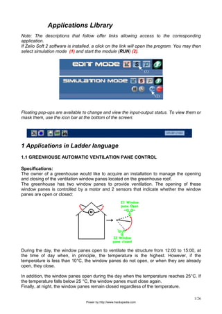
  • 1. 1/26 Applications Library Note: The descriptions that follow offer links allowing access to the corresponding application. If Zelio Soft 2 software is installed, a click on the link will open the program. You may then select simulation mode (1) and start the module (RUN) (2). (1) (2) Floating pop-ups are available to change and view the input-output status. To view them or mask them, use the icon bar at the bottom of the screen: 1 Applications in Ladder language 1.1 GREENHOUSE AUTOMATIC VENTILATION PANE CONTROL Specifications: The owner of a greenhouse would like to acquire an installation to manage the opening and closing of the ventilation window panes located on the greenhouse roof. The greenhouse has two window panes to provide ventilation. The opening of these window panes is controlled by a motor and 2 sensors that indicate whether the window panes are open or closed: During the day, the window panes open to ventilate the structure from 12:00 to 15:00, at the time of day when, in principle, the temperature is the highest. However, if the temperature is less than 10°C, the window panes do not open, or when they are already open, they close. In addition, the window panes open during the day when the temperature reaches 25°C. If the temperature falls below 25 °C, the window panes must close again. Finally, at night, the window panes remain closed regardless of the temperature. Power by http://www.hackspedia.com
  • 2. 2/26 Summary diagram: Description of the inputs/ouputs: INPUTS: OUTPUTS: I1 Opened window sensor Q1 Opening of the window panes I2 Closed window sensor Q2 Closing of the window panes IB Temperature (analog input) The temperature is supplied by a sensor with output voltage of 0 to 10 V. Model Required: Zelio Logic with clock and analog inputs. SR2 B121 BD (24 V DC) ou SR2 B121 JD (12 V DC) par exemple. Program Description: 3 time ranges are used: -Range 1: Night, from 21:00 to 07:00 -Range 2: Daytime, from 7:00 to 12:00 a.m. and from 3:00 to 9:00 p.m. -Range 3: Noon, from 12:00 to 15:00 Power by http://www.hackspedia.com
  • 3. 3/26 Logic diagram: Click on the link below to access the application: Greenhouse automatic ventilation pane control (ladder) Note: Use the floating pop-up of analog input IB to vary the temperature. To call it up, click on the corresponding icon in the lower bar. Power by http://www.hackspedia.com
  • 4. 4/26 1.2 INDOOR/OUTDOOR LIGHTING OF A HOME Specifications: A homeowner would like to install a system capable of controlling the lighting of a stairway and outdoor entrance providing access to the home. Outdoor Lighting: The circuit is activated at night by a twilight switch. A sensor detects any passage and activates the outdoor lighting for 2 minutes. Indoor lighting: Two push-buttons are situated in the stairwell: one in the entrance, the other at the top of the stairs. Their function is identical. Time-delayed (2 minutes) lighting is obtained by quickly pressing one of the buttons. Description of the inputs/ouputs: INPUTS: OUTPUTS: I1 Passage sensor Q1 Outdoor lighting I2 Twilight switch Q2 Indoor lighting I3 Pushbutton I4 Pushbutton Model Required: No specific condition: SR2 B121 BD (24 VDC) for example. Logic diagram: Click on the link below to access the application: Indoor/Outdoor lightning of a home Power by http://www.hackspedia.com
  • 5. 5/26 1.3 ACCESS CONTROL, AUTOMATIC GATE Specifications: A homeowner wants access to his residence to be controlled by an automatic gate equipped with a dual direction (opening and closure) motor. Opening: Whether the gate is closed or in an intermediate position, the remote control signal causes the full opening of the gate. During the opening process, any new action on the remote control stops or restarts the motor. As soon as the gate is fully open, a 4-second time delay delays its closure. Closure: During the closing process, if the remote control is activated or if the sensor detects a passage, the gate is opened. As long as the sensor is activated, (vehicle stopped in the passage way for example), the gate remains fully open. Description of the inputs/ouputs: INPUTS: OUTPUTS: I1 Remote control Q1 Gate opening I2 Gate closed position Q2 Gate closure I3 Gate closed position I4 Passage sensor Model Required: No specific condition. SR2 B121 BD (24 V DC) or SR2 B121 JD (12 V DC) for example. Advantages of the application: The safety feature of being able to stop gate opening or closing via the remote control signal is an essential advantage for this type of application. Power by http://www.hackspedia.com
  • 6. 6/26 Logic diagram: Click on the link below to access the application: Access control, automatic gate Power by http://www.hackspedia.com
  • 7. 7/26 1.4 UNDERGROUND CAR PARK CONTROL Specifications: We want to complete and centralize the control of the underground car park of an administration building. Vehicle entrance/exit control: access is allowed by an automatic barrier. Users can access the car park during business hours: Monday through Friday from 8:30 a.m. to 5:30 p.m., Saturday from 9:30 to noon. However, it is possible to manually inhibit the blocking of the barrier by pressing on Z4 (function restored by pressing on Z2) in case of an exceptional event. Counting: The car park capacity is limited to 93 vehicles. A counter will block access to the car park if it is full and will control a light panel indicating ‘’Car park Full’’. It is also possible to manually increase or decrease (in increments) the number of vehicles present in the car park (using Z1 and Z3). CO2 level: For safety reasons, a CO2 sensor indicates when the level is high and controls the operation of a fan (10 minutes). Light: The lighting switches on for 2 minutes each time a vehicle enters the car park or whenever a pedestrian presses the switch. . Description of the inputs/ouputs: INPUTS: OUTPUTS: I1 Vehicle entry Q1 Indicates when the car park is full. I2 Vehicle exit Q2 Locks the entry barrier I3,I4 Pushbuttons at pedestrian access points Q3 Lightning IB Carbon dioxide level sensor Q4 Fan control Z1 Manually increments the number of vehicles Z2 Resumes automatic entry control Z3 Manually decrements the number of vehicles Z4 Manual release of entry barrier Model Required: Model with clock and analog inputs. SR2 B121 BD (24 V DC) or SR2 B121 JD (12 V DC) for example. Advantages of the application: Full car park control using a single logic module. Note: Use the floating pop-ups to simulate the variation of the level of CO2 (analog input IB) and to use the push-buttons. To call them up, click on the corresponding icons in the lower bar. Power by http://www.hackspedia.com
  • 8. 8/26 Logic diagram: Click on the link below to access the application: Underground car park control Power by http://www.hackspedia.com
  • 9. 9/26 1.5 ROOM TEMPERATURE REGULATION Specifications: The ambient temperature of a room is controlled in the heat mode by a heater and a fan, and in the chill mode only by the fan. A heat sensor provides a 0-10 V signal. A switch is used to deactivate temperature regulation. The direct evolution of inputs and outputs can be monitored in a supervision window. Description of the inputs/ouputs: INPUTS: OUTPUTS: I1 On/Off switch Q1 Heater I2 Mode selection Q2 Fan IB Ambient temperature (analog input) IC Setpoint (analog input) The temperature is supplied by a sensor with output voltage of 0 to 10 V. Model Required: Zelio Logic with analog inputs. SR2 B121 BD (24 V DC) or SR2 B121 JD (12 V DC) for example. Program Description: Input I1 =0 : regulation is off. Input I1 =1 : Regulation is on. Input I2 =0 : chill mode. Input I2 =1 : heat mode. Hysteresis: Advantages of the application: Use of 0-10 V analog inputs. The supervision window. Power by http://www.hackspedia.com
  • 10. 10/26 Logic diagram: Power by http://www.hackspedia.com
  • 11. 11/26 Supervision window: Click on the link below to access the application: Room temperature regulation Note: to simulate this program, first adjust the setpoint using analog input IC then switch on the temperature regulation (I1=1, click on I1). If the chill mode is selected (I2=0), the fan will be activated as soon as the temperature exceeds the setpoint of 3°C and will stop when it drops 2°C below the setpoint. And conversely for the heat mode. Power by http://www.hackspedia.com
  • 12. 12/26 1.6 PROGRESSIVE HEATING OF BOILER ELEMENTS Specifications: To avoid over-consumption on boiler start-up, the heating elements are heated progressively, and stopped progressively when the boiler is stopped. This operating principle is shown by the following timing diagram: An “On” (MA) button authorizes the activation of the first heating element (S1). After a time-delay T, the second element (S2) starts up. After the same time-delay, the third elements starts up (S3), then the fourth element (S4) again after time-delay T. An “Off” (AR) button deactivates S1. The three other elements are progressively deactivated after time-delay T with each deactivation of the preceding element. Description of the inputs/ouputs: INPUTS: OUTPUTS: I1 On button Q1 First heating element S1 I2 Off button Q2 Second heating element S2 Q3 Third heating element S3 Q4 Fourth heating element S4 Model Required: No specific condition: SR2 B121 BD (24 V DC) or SR2 B121 JD (12 V DC) for example. Program Description: In principle, time delay T is identical for the activation/deactivation of all the heating elements. The program includes three TIMER function blocks. The function to perform according to the specifications requires entering the same time-delay value in the three blocks. As a result, if the user wants to modify one of them, he/she will have to enter the new selection in the three blocks. Power by http://www.hackspedia.com
  • 13. 13/26 Logic diagram: Click on the link below to access the application: Boiler elements Power by http://www.hackspedia.com
  • 14. 14/26 2 Applications in FBD language 2.1 GREENHOUSE AUTOMATIC VENTILATION PANE CONTROL Specifications: The owner of a greenhouse would like to acquire an installation to manage the opening and closing of the ventilation window panes located on the greenhouse roof. The greenhouse has two window panes to provide ventilation. The opening of these window panes is controlled by a motor and 2 sensors that indicate whether the window panes are open or closed: During the day, the window panes open to ventilate the structure from 12:00 to 15:00, at the time of day when, in principle, the temperature is the highest. However, if the temperature is less than 10°C, the window panes do not open, or when they are already open, they close. In addition, the window panes open during the day when the temperature reaches 25°C. If the temperature falls below 25 °C, the window panes must close again. Finally, at night, the window panes remain closed regardless of the temperature. Summary diagram: Description of the inputs/ouputs: INPUTS: OUTPUTS: I1 Opened window sensor Q1 Opening of the window panes I2 Closed window sensor Q2 Closing of the window panes IB Temperature (analog input) The temperature is supplied by a sensor with output voltage of 0 to 10 V. Model Required: Power by http://www.hackspedia.com
  • 15. 15/26 Zelio Logic with clock and analog inputs. SR2 B121 BD (24 V DC) or SR2 B121 JD (12 V DC) for example. Program Description: 3 time ranges are used: -Range 1: Night, from 21:00 to 07:00 (B13) -Range 2: Daytime, from 7:00 a.m. to 12:00 p.m. and from 3:00 to 9:00 p.m. (B12) -Range 3: Noon, from 12:00 to 15:00 (B11) Advantages of the application: The programmable logic function is used simplifying the diagram Logic diagram: Click on the link below to access the application: Greenhouse automatic ventilation pane control (FBD) Power by http://www.hackspedia.com
  • 16. 16/26 2.2 INDOOR/OUTDOOR LIGHTING OF A HOME Specifications: A homeowner would like to install a system capable of controlling the lighting of a stairway and outdoor entrance providing access to the home. Outdoor lighting: The circuit is activated every year from June 1st to October 1st and at night by a twilight switch. A sensor detects any passage and activates the outdoor lighting for 2 minutes. Indoor lighting: Two pushbuttons are situated in the stairwell; one in the entrance, the other at the top of the stairs. Their function is identical. • Time-delayed (30 seconds) lighting is obtained by quickly pressing one of the buttons. The timer can be inhibited by renewed action on one of the buttons. • Permanent lighting is activated if one button is depressed for at least 2 seconds. A quick press stops it. Table of inputs/outputs: INPUTS: OUTPUTS: I1 Passage sensor Q1 Outdoor lighting I2 Twilight switch Q4 Indoor lighting I3 Pushbutton I4 Pushbutton Model Required: Zelio Logic with clock: SR2 B121 BD (24 VDC) for example. Program Description: Programming is possible at two levels. Level 1 : Program satisfying the specifications. Level 2: Use of SFC/Grafcet functions Advantages of the application: It is possible to handle the application with sequential functions. Power by http://www.hackspedia.com
  • 17. 17/26 Logic diagram Level 1: Click on the link below to access the application: Indoor/Outdoor lightning of a home - level 1 Power by http://www.hackspedia.com
  • 18. 18/26 Logic diagram Level 2 (SFC/Grafcet) : Click on the link below to access the application: Indoor/Outdoor lightning of a home - level 2 (SFC-Grafcet) Power by http://www.hackspedia.com
  • 19. 19/26 2.3 ACCESS CONTROL, AUTOMATIC GATE Specifications: A homeowner wants access to his residence to be controlled by an automatic gate equipped with a dual direction (opening and closure) motor. Opening: Whether the gate is closed or in an intermediate position, the remote control signal causes the full opening of the gate. During the opening process, each new action on the remote control stops or restarts the motor. As soon as the gate is fully open, a 4-second time delay delays its closure. Closure: During the closing process, if the remote control is activated or if the sensor detects a passage, the gate is opened. As long as the sensor is activated, (vehicle stopped in the passage way for example), the gate remains fully open. Description of the inputs/ouputs: INPUTS: OUTPUTS: I1 Remote control Q1 Gate opening I2 Gate closed position Q2 Gate closure I3 Gate closed position I4 Passage sensor Model Required: No specific condition. SR2 B121 BD (24 V DC) or SR2 B121 JD (12 V DC) for example. Program Description: The T1 timer (A-C Timer A-C) is used to switch the motor in the opening direction 0.5 seconds after the inhibition of closure. This avoids any short-circuit and mechanical jerk. Timer T2 (A-C Timer) fulfills two simultaneous functions. The 4-second triggering delay maintains the gate in the open position before beginning to closing motion.. The 0.2 second triggering delay allows the activation conditions of the ‘’AND’’ logic block output to be verified. Advantages of the application: The safety feature of being able to stop gate opening or closing via the remote control signal is an essential advantage for this type of application. The parallel connection to the motor terminals allows the addition of a light signal indicating any movement of the gate. Power by http://www.hackspedia.com
  • 20. 20/26 Logic diagram: Click on the link below to access the application: Access control, automatic gate Power by http://www.hackspedia.com
  • 21. 21/26 2.4 ROOM TEMPERATURE REGULATION Specifications: The ambient temperature of a room is controlled in the heat mode by a heater and a fan, and in the chill mode only by the fan. A temperature sensor, via a converter, provides a 0- 10V signal. A switch is used to deactivate temperature regulation. Screen display: The heat or chill mode is displayed The ambient temperature and setpoint are displayed. A trigger function is provided to set up regulation that takes into account a hysteresis of +2°C from start to stop and –3°C from stop to start. Description of the inputs/ouputs: INPUTS: OUTPUTS: I1 On/Off switch Q1 Heater I2 Mode selection Q4 Fan IB Ambient temperature (analog input) IC Setpoint (analog input) The temperature is supplied by a sensor with output voltage of 0 to 10 V. Model Required: Zelio Logic with analog inputs. SR2 B121 BD (24 V DC) or SR2 B121 JD (12 V DC) for example. Program Description: Input I1 =0 : regulation is off. Display example: *********** OFF *********** 0017.2 InputI1 =1 : Regulation is on. Display example: heat mode. 0020.0 (setpoint display) 0017.2 (temperature display) Power by http://www.hackspedia.com
  • 22. 22/26 Hysteresis: Advantages of the application: Use of 0-10 V analog inputs. Logic diagram: Note 1: When the module is on, select FBD DISPLAY in the main menu of the module to view the active text blocks on the screen. In a simulation, it is possible to call up the front panel by selecting 3 Front Panel in the Window menu. Note 2: It will probably be necessary to wire additional gain functions after inputs IB and IC. Click on the link below to access the application: Room temperature regulation Power by http://www.hackspedia.com
  • 23. 23/26 2.5 PROGRESSIVE HEATING OF BOILER ELEMENTS Specifications: To avoid over-consumption on boiler start-up, the heating elements are heated progressively, and stopped progressively when the boiler is stopped. This operating principle is shown by the following timing diagram: An “On” (MA) button authorizes the activation of the first heating element (S1). After a time delay T, the second element (S2) starts up. After the same time-delay, the third elements starts up (S3), then the fourth element (S4) again after time-delay T. An “Off” (AR) button deactivates S1. The three other elements are progressively deactivated after time-delay T with each deactivation of the preceding element. Description of the inputs/ouputs: INPUTS: OUTPUTS: I1 On button Q1 First heating element S1 I2 Off button Q2 Second heating element S2 Q3 Third heating element S3 Q4 Fourth heating element S4 Model Required: No specific condition. SR2 B121 BD (24 V DC) or SR2 B121 JD (12 V DC) for example. Program Description: In principle, time delay T is identical for the activation/deactivation of all the heating elements. The program includes three TIMER function blocks. The function to perform according to the specifications requires entering the same time-delay value in the three blocks. As a result, if the user wants to modify one of them, he/she will have to enter the new selection in the three blocks. Power by http://www.hackspedia.com
  • 24. 24/26 Logic diagram: Click on the link below to access the application: Progressive heating of boiler elements Power by http://www.hackspedia.com
  • 25. 25/26 2.6 SCHOOL BELL Specifications: A high school wants to control the daily bell and alarm system using the same device. The bell rings from Monday to Friday for one minute except during the holidays. The “alarm” mode is active during the holidays, on weekends, and at night Monday through Friday. The alert is given for 1 minute by an audio signal alternating 2 s ON, 1 s OFF, and by an indicator light activated by a motion detector. It must be possible to reset the alarm. Advantages of the application: The annual clock, available on FBD, allows school holidays and legal holidays to be taken into account. Description of the inputs/ouputs: INPUTS: OUTPUTS: I1 Alarm : On/off Q1 Ringing I2 Motion detector Q2 Indicator light I3 Alarm: Reset Model Required: Model with annual clock: SR2 B121 BD (24 V DC) or SR2 B121 JD (12 V DC) for example. Program Description: To program the three clocks, copy or adapt the parameters of figures 1, 2 and 3. The logic block unites the activation conditions of the “alarm” mode according to the equation : INPUT 1 2 3 4 OUTPUT Time 2 I1 I2 Time 3 0 1 1 1 1 Figure 1: Power by http://www.hackspedia.com
  • 26. 26/26 Figure 2: Figure 3: Logic diagram: Click on the link below to access the application: School bell Power by http://www.hackspedia.com