Download as PDF, PPTX

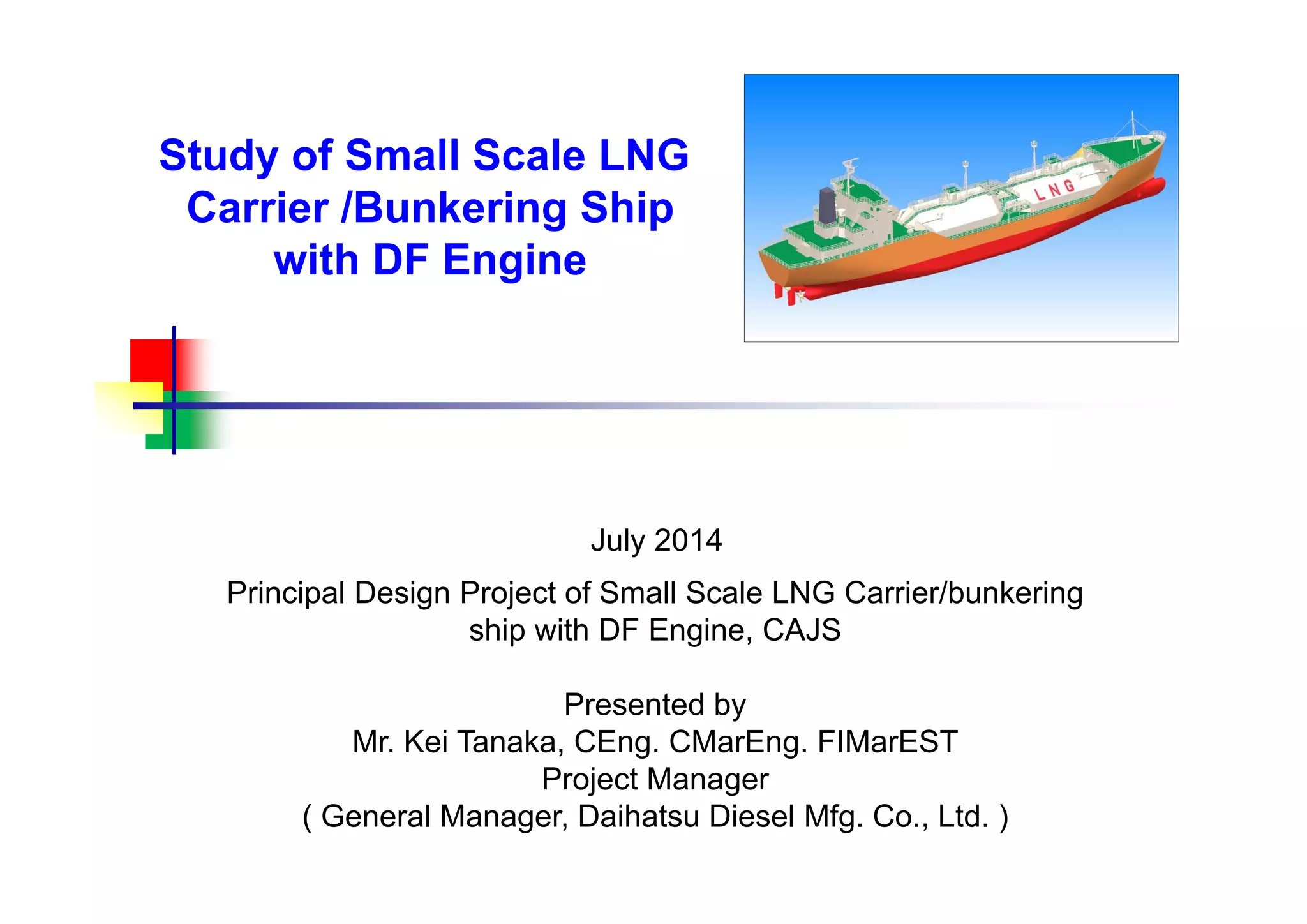
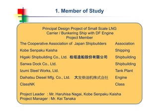

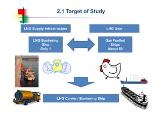
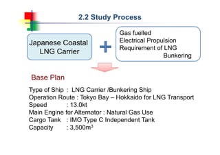

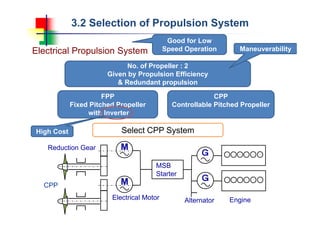
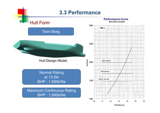
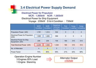
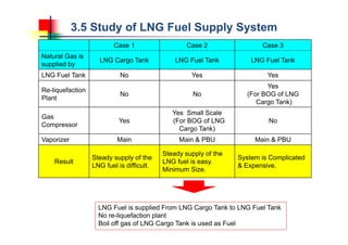

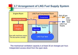

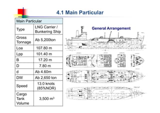
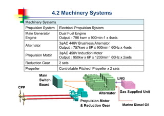
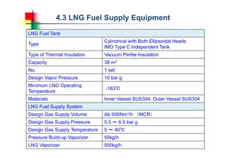
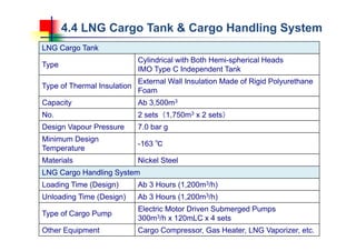

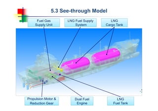
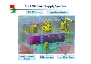
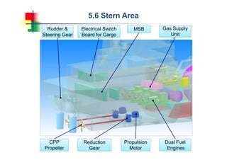
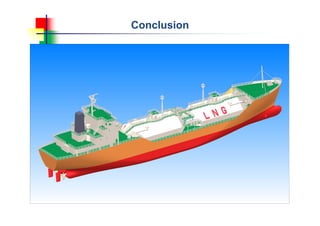

This document summarizes a study on designing a small-scale LNG carrier and bunkering ship with a dual-fuel engine. The study involved multiple Japanese shipbuilding and engineering companies. The target was to increase natural gas use by developing an LNG bunkering ship and coastal LNG carriers. The selected design used a dual-fuel engine, electrical propulsion system, 3,500 cubic meter LNG cargo tanks, a 38 cubic meter LNG fuel tank, and an LNG fuel supply system to provide fuel from the cargo tanks. The presentation concludes by thanking ClassNK for supporting the joint industry research program.


![Emsa --final-report-bunkering-lng op-06_2012_b[1]](https://cdn.slidesharecdn.com/ss_thumbnails/emsa-final-report-bunkering-lngop062012b1-131120023037-phpapp01-thumbnail.jpg?width=640&height=640&fit=bounds)


![[Deck] What's New in Spark-Iceberg Integration via DSV2.pptx](https://cdn.slidesharecdn.com/ss_thumbnails/deckwhatsnewinspark-icebergintegrationviadsv2-260210005337-25955b12-thumbnail.jpg?width=640&height=640&fit=bounds)