This document provides an overview of routing protocols and path selection algorithms. It discusses the main types of routing protocols including distance vector protocols like RIP, link-state protocols like OSPF, path vector protocols like BGP, and hybrid protocols like EIGRP. It describes how each protocol uses different algorithms and metrics to determine the best path, avoid loops, and populate the routing table. Key topics covered include distance vector algorithms, link-state algorithms, path vector algorithms, and the role of the routing and forwarding tables in path selection.

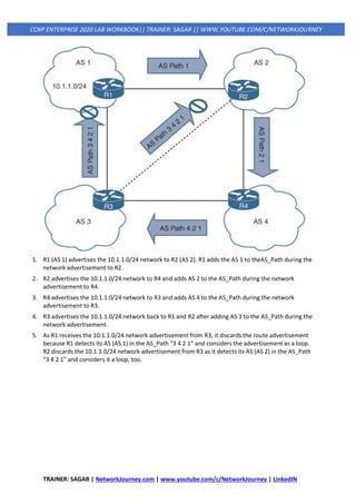
![TRAINER: SAGAR | NetworkJourney.com | www.youtube.com/c/NetworkJourney | LinkedIN
CCNP ENTERPRISE 2020 LAB WORKBOOK|| TRAINER: SAGAR || WWW.YOUTUBE.COM/C/NETWORKJOURNEY
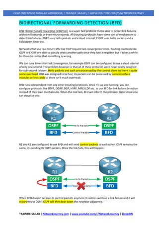
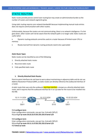
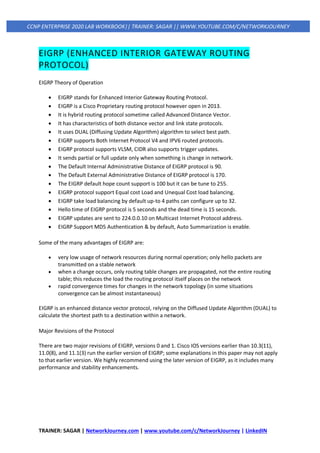
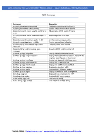
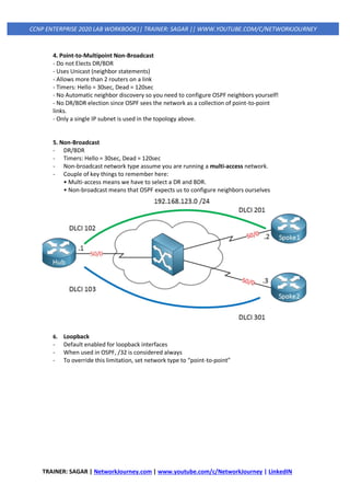
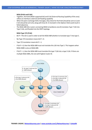
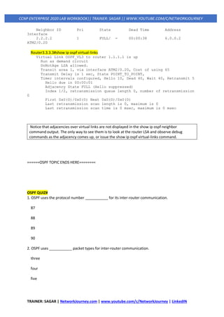
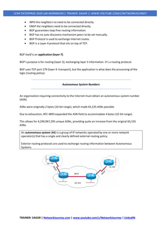
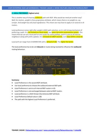
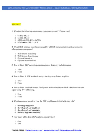
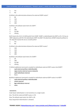
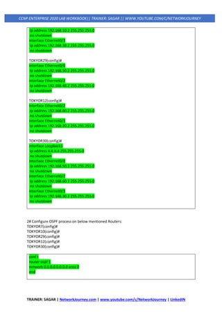
Equal-Cost Multipathing
If a routing protocol identifies multiple paths as a best path and supports multiple path entries, the
router installs the maximum number of paths allowed per destination. This is known as equal-cost
multipathing (ECMP) and provides load sharing across all links. RIP, EIGRP, OSPF, and IS-IS all support
ECMP. ECMP provides a mechanism to increase bandwidth across multiple paths by splitting traffic
equally across the links.
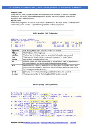
R1# show ip route
! Output omitted for brevity
O 10.3.3.0/24 [110/30] via 10.12.1.2, 00:49:12, GigabitEthernet0/2
[110/30] via 10.14.1.4, 00:49:51, GigabitEthernet0/4
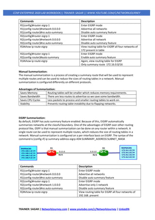
Unequal-Cost Load Balancing
By default, routing protocols install only routes with the lowest path metric. However, EIGRP can be
configured (not enabled by default) to install multiple routes with different path metrics. This allows
for unequal-cost load balancing across multiple paths. Traffic is transmitted out the router’s
interfaces based on that path’s metrics in ratio to other the interface’s metrics.
OSPF](https://image.slidesharecdn.com/3iprouting-pbrbfd-v2-200820144352/85/3-ip-routing-pbr-bfd-v2-11-320.jpg)
![TRAINER: SAGAR | NetworkJourney.com | www.youtube.com/c/NetworkJourney | LinkedIN
CCNP ENTERPRISE 2020 LAB WORKBOOK|| TRAINER: SAGAR || WWW.YOUTUBE.COM/C/NETWORKJOURNEY
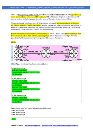
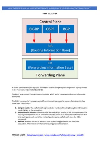
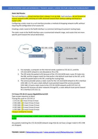
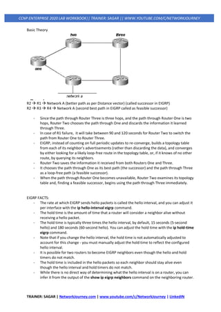
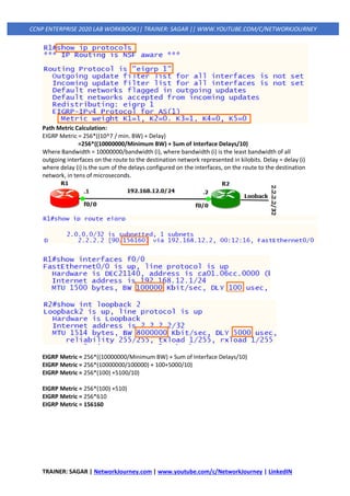
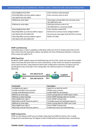
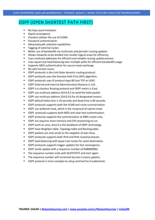
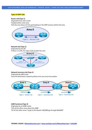
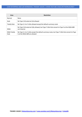
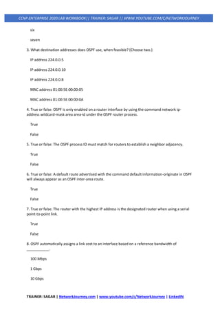
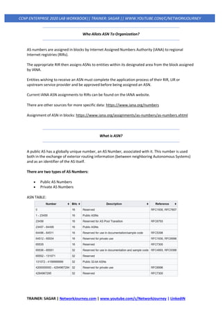
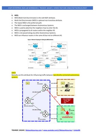
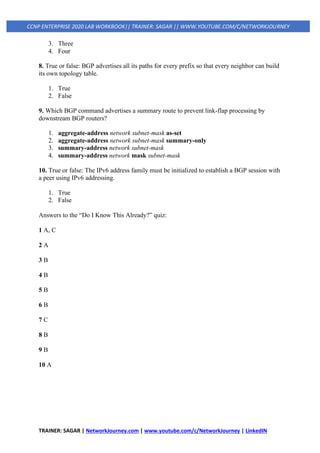
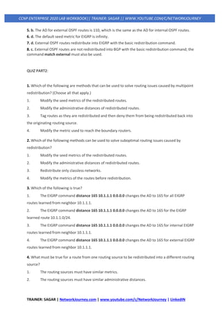
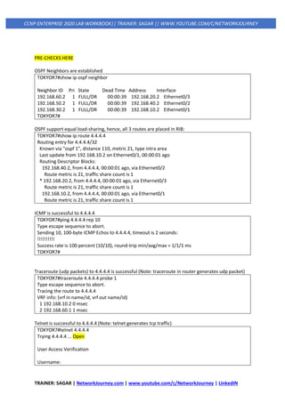
R1# show ip route eigrp
! Output omitted for brevity
Gateway of last resort is not set
10.0.0.0/8 is variably subnetted, 7 subnets, 2 masks
D 10.3.3.0/24 [90/3328] via 10.14.1.4, 00:00:02, GigabitEthernet0/4
[90/5632] via 10.12.1.2, 00:00:02, GigabitEthernet0/2](https://image.slidesharecdn.com/3iprouting-pbrbfd-v2-200820144352/85/3-ip-routing-pbr-bfd-v2-12-320.jpg)

![TRAINER: SAGAR | NetworkJourney.com | www.youtube.com/c/NetworkJourney | LinkedIN
CCNP ENTERPRISE 2020 LAB WORKBOOK|| TRAINER: SAGAR || WWW.YOUTUBE.COM/C/NETWORKJOURNEY
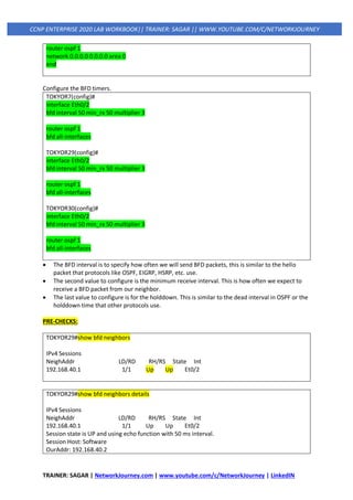
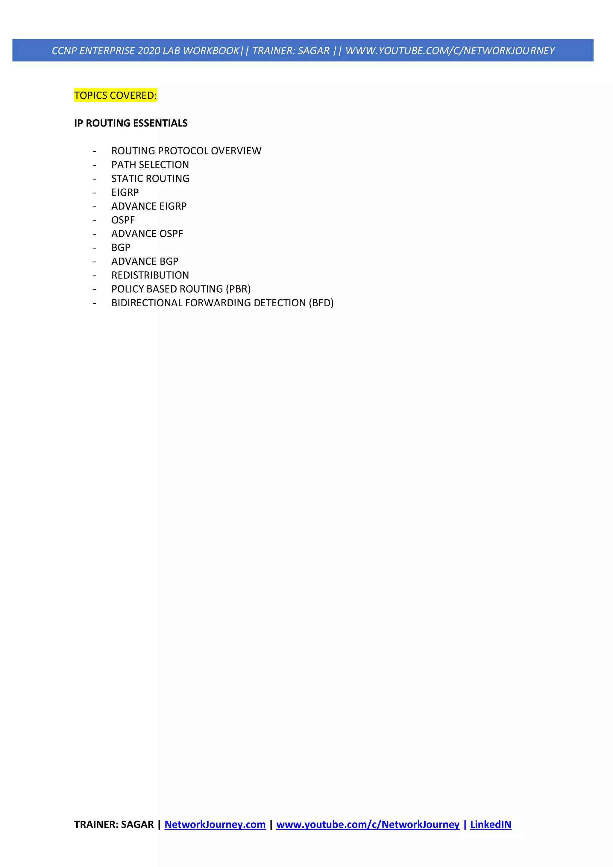
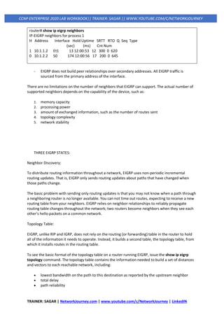
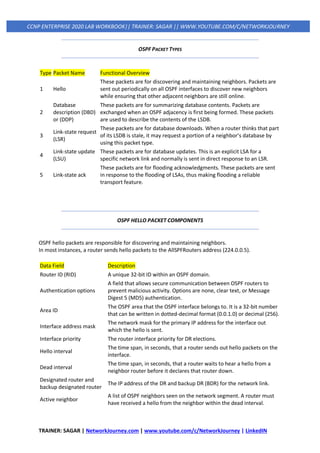
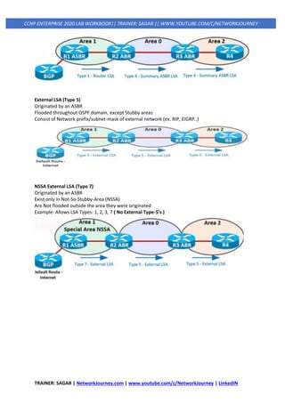
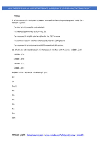
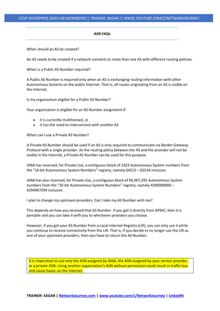
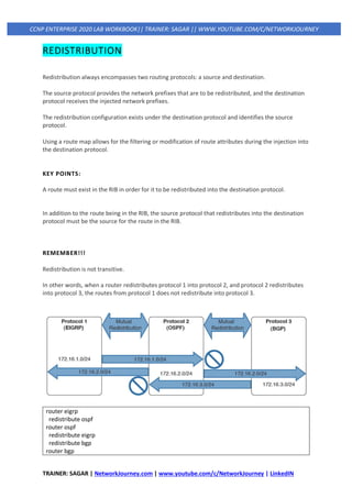
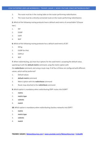
10.0.0.0/8 is variably subnetted, 5 subnets, 2 masks
C 10.11.11.0/24 is directly connected, GigabitEthernet0/1
C 10.12.1.0/24 is directly connected, GigabitEthernet0/0
S 10.22.22.0/24 [1/0] via 10.12.1.2
Advantage:
Static route recursion can simplify topologies if a link fails because it may allow the static route to
stay installed while it changes to a different outbound interface in the same direction as the
destination.
Disadvantage:
However, problems arise if the recursive lookup resolves to a different interface pointed in the
opposite direction.
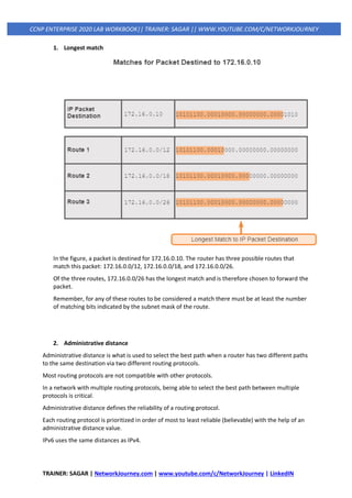
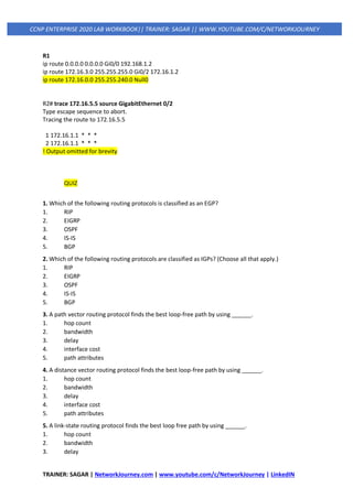
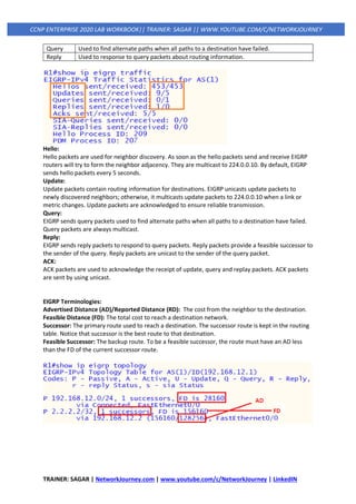
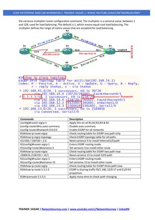
3. Fully Specified Static Routes
To correct this issue, the static route configuration should use the outbound interface and the next-
hop IP address. A static route with both an interface and a next-hop IP address is known as a fully
specified static route.
If the interface listed is not in an up state, the router removes the static route from the RIB.
Specifying the next-hop address along with the physical interface removes the recursive lookup and
does not involve the ARP processing problems that occur when using only the outbound interface.
Fully specified static routes are configured with the command ip route network subnet-mask
interface-id next-hop-ip.
R1# configure term
Enter configuration commands, one per line. End with CNTL/Z.
R1(config)# ip route 10.22.22.0 255.255.255.0 GigabitEthernet0/0 10.12.1.2
R2# configure term
Enter configuration commands, one per line. End with CNTL/Z.
R2(config)# ip route 10.11.11.0 255.255.255.0 GigabitEthernet0/0 10.12.1.
R1# show ip route
! Output omitted for brevity
10.0.0.0/8 is variably subnetted, 5 subnets, 2 masks
C 10.11.11.0/24 is directly connected, GigabitEthernet0/1
C 10.12.1.0/24 is directly connected, GigabitEthernet0/0
S 10.22.22.0/24 [1/0] via 10.12.1.2, GigabitEthernet0/0](https://image.slidesharecdn.com/3iprouting-pbrbfd-v2-200820144352/85/3-ip-routing-pbr-bfd-v2-15-320.jpg)
![TRAINER: SAGAR | NetworkJourney.com | www.youtube.com/c/NetworkJourney | LinkedIN
CCNP ENTERPRISE 2020 LAB WORKBOOK|| TRAINER: SAGAR || WWW.YOUTUBE.COM/C/NETWORKJOURNEY
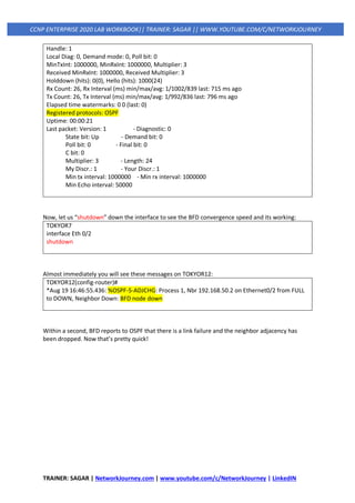
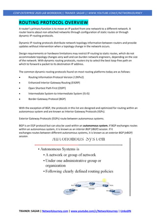
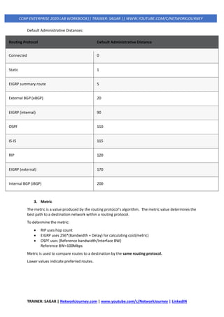
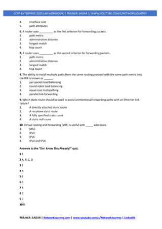
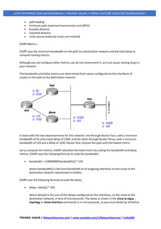
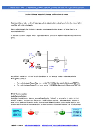
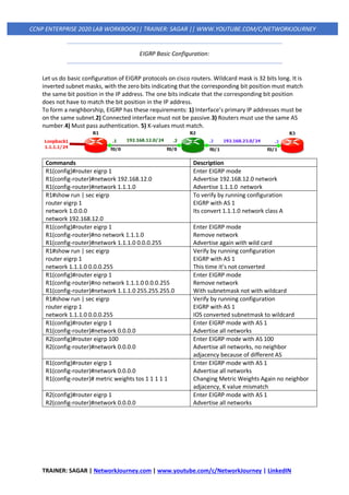
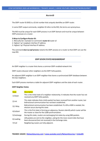
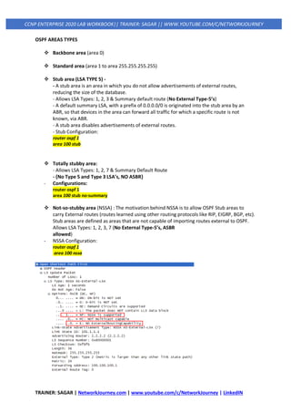
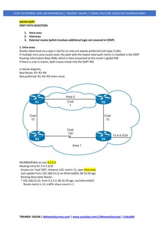
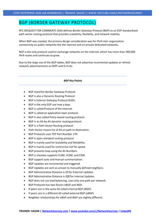
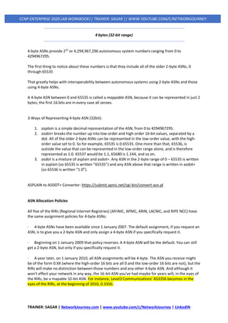
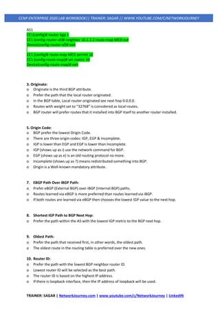
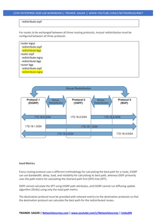
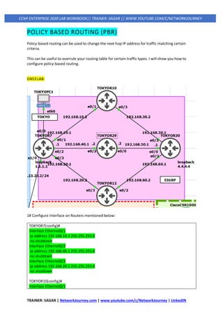
Floating Static Routing
The default AD on a static route is 1, but a static route can be configured with an AD value of 1 to
255 for a specific route.
The AD is set on a static route by appending the AD as part of the command structure.
Using a floating static route is a common technique for providing backup connectivity for prefixes
learned via dynamic routing protocols.
A floating static route is configured with an AD higher than that of the primary route. Because the
AD is higher than that of the primary route, it is installed in the RIB only when the primary route is
withdrawn.
R1# configure terminal
Enter configuration commands, one per line. End with CNTL/Z.
R1(config)# ip route 10.22.22.0 255.255.255.0 10.12.1.2 10
R1(config)# ip route 10.22.22.0 255.255.255.0 Serial 1/0 210
R1# show ip route
! Output omitted for brevity
Gateway of last resort is not set
10.0.0.0/8 is variably subnetted, 5 subnets, 2 masks
C 10.11.11.0/24 is directly connected, GigabitEthernet0/1
C 10.12.1.0/24 is directly connected, GigabitEthernet0/0
C 10.12.2.0/24 is directly connected, Serial1/0
S 10.22.22.0/24 [10/0] via 10.12.1.2](https://image.slidesharecdn.com/3iprouting-pbrbfd-v2-200820144352/85/3-ip-routing-pbr-bfd-v2-16-320.jpg)
![TRAINER: SAGAR | NetworkJourney.com | www.youtube.com/c/NetworkJourney | LinkedIN
CCNP ENTERPRISE 2020 LAB WORKBOOK|| TRAINER: SAGAR || WWW.YOUTUBE.COM/C/NETWORKJOURNEY
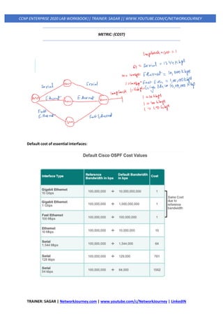
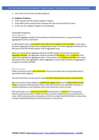
you use it in this formula. Throughout this paper, we use delay as it is configured and shown
on the interface.
EIGRP uses these scaled values to determine the total metric to the network:
• metric = ([K1 * bandwidth + (K2 * bandwidth) / (256 - load) + K3 * delay] * [K5 / (reliability +
K4)]) * 256
Note: These K values should be used after careful planning. Mismatched K values prevent a neighbor
relationship from being built, which can cause your network to fail to converge.
Note: If K5 = 0, the formula reduces to Metric = ([k1 * bandwidth + (k2 * bandwidth)/(256 - load) +
k3 * delay]) * 256.
The default values for K are:
• K1 = 1
• K2 = 0
• K3 = 1
• K4 = 0
• K5 = 0
For default behavior, you can simplify the formula as follows:
metric = bandwidth + delay
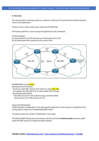
In this example, the total cost through Router Four is:
minimum bandwidth = 56k
total delay = 100 + 100 + 2000 = 2200
[(10000000/56) + 2200] x 256 = (178571 + 2200) x 256 = 180771 x 256 = 46277376
And the total cost through Router Three is:
minimum bandwidth = 128k
total delay = 100 + 100 + 1000 = 1200
[(10000000/128) + 1200] x 256 = (78125 + 1200) x 256 = 79325 x 256 = 20307200
So, to reach Network A, Router One chooses the route through Router Three.
EIGRP Tables:
EIGRP maintains three tables. 1) Neighbor Table, 2) Topology Table and 3) Routing Table.
Neighbor Table:
Neighbor table includes all neighbors that is directly connected to router using EIGRP. In simple
words, next hop router and the interfaces.](https://image.slidesharecdn.com/3iprouting-pbrbfd-v2-200820144352/85/3-ip-routing-pbr-bfd-v2-24-320.jpg)
![TRAINER: SAGAR | NetworkJourney.com | www.youtube.com/c/NetworkJourney | LinkedIN
CCNP ENTERPRISE 2020 LAB WORKBOOK|| TRAINER: SAGAR || WWW.YOUTUBE.COM/C/NETWORKJOURNEY
AS Autonomous System number 1
Codes Passive is good and Active is bad
Sia Status (Stuck in
Active)
EIGRP has not received a reply to a query packet from one of the neighbors
within the allowed time about 3 minutes.
1 Successors The best path In this case only one way to get to the destination
FD is 2816 Feasible Distance: Total distance to get to the destination
28416/28160 First, one is Feasible Distance. The second Value is Advertised Distance
EIGRP Routing Table Explanation:
D Shows this is an EIGRP learnt route
192.168.3.0/24 Destination learn network and 24 is subnet mask.
90 90, is the Administrative Distance of EIGRP.
3072 This is the metric, Total distance to get to the destination
192.168.2.3 The neighbor that advertised the route.
00:49:16 Time since the route was learnt.
GigabitE1/0 The outbound interface going towards the destination.
EIGRP Metric:
EIGRP uses metric to select the best route from all available routes for destination. Metric has five
components.1.Bandwidth, 2.Load, 3.Delay, 4.Reliability and 5.MTU. From these only bandwidth and
delay are by default enabled.
K Value Component Description
K1 Bandwidth Lowest bandwidth of route
K2 Load Worst load on route based on packet rate
K3 Delay Cumulative interface delay of route
K4 Reliability Worst reliability of route based on keep alive
K5 MTU Smallest MTU in path [Not used in route calculation]](https://image.slidesharecdn.com/3iprouting-pbrbfd-v2-200820144352/85/3-ip-routing-pbr-bfd-v2-26-320.jpg)
![TRAINER: SAGAR | NetworkJourney.com | www.youtube.com/c/NetworkJourney | LinkedIN
CCNP ENTERPRISE 2020 LAB WORKBOOK|| TRAINER: SAGAR || WWW.YOUTUBE.COM/C/NETWORKJOURNEY
Path Selection Optimization:
Change EIGRP metrics by manipulating the bandwidth and/or delay values. Changing the bandwidth
value is not recommended because that value is used for many other reasons and features in the
router. Also, configure the K-Values to influence the EIGRP metric calculation.
Commands Description
R6#show ip route eigrp
D 7.7.7.7 [90/156160] via 192.168.76.7, F0/1
[90/156160] via 192.168.67.7, F0/0
First verify both routes in routing table
Equal path load balancing
R6(config)#interface FastEthernet 0/0
R6(config-if)# bandwidth 10000
Enter interface mode
Decrease the bandwidth to 10000
R6#show ip route eigrp Verify again only one path now
R6(config)#interface FastEthernet 0/0
R6(config-if)#no bandwidth 10000
Enter interface mode
Make the default bandwidth again
R6#show ip route eigrp Check again both path back
R6(config)#interface FastEthernet 0/0
R6(config-if)#delay 200
Enter interface mode
Increase the delay this time
R6#show ip route eigrp Verify again only one path now
R6(config)#interface FastEthernet 0/0
R6(config-if)#no delay 200
Enter interface mode
Make the default delay again
R6#show ip route eigrp
D 7.7.7.7 [90/156160] via 192.168.76.7, F0/1
[90/156160] via 192.168.67.7, F0/0
First verify both routes in routing table
Equal path load balancing
R6(config)#router eigrp 1
R6(config-router)#metric weights 0 1 1 1 1 1
Enter EIGRP mode
Change k Values
R7(config)#router eigrp 1
R7(config-router)#metric weights 0 1 1 1 1 1
Enter EIGRP mode
Change K values
R6#show ip route eigrp
D 7.7.7.7 [90/610]
Verify the eigrp routes different FD
R6(config)#interface FastEthernet 0/0
R6(config-if)# bandwidth 10000
R6(config-if)#delay 200
Enter interface mode
Decrease the bandwidth to 10000
Increase the delay Change metric
EIGRP Packet Types:
EIGRP uses five packet types in communication with its neighbors. The packet types are below.
Packet Description
Hello Used to identify neighbors. They are sent as periodic multicasts.
Update Used to advertise routes, only sent as multicasts when something is changed.
Ack Acknowledges receipt of an update.](https://image.slidesharecdn.com/3iprouting-pbrbfd-v2-200820144352/85/3-ip-routing-pbr-bfd-v2-28-320.jpg)
![TRAINER: SAGAR | NetworkJourney.com | www.youtube.com/c/NetworkJourney | LinkedIN
CCNP ENTERPRISE 2020 LAB WORKBOOK|| TRAINER: SAGAR || WWW.YOUTUBE.COM/C/NETWORKJOURNEY
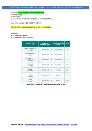
The connected network for the OSPF-enabled interface is added to the OSPF LSDB under the
corresponding OSPF area in which the interface participates. Secondary connected networks are
added to the LSDB only if the secondary IP address matches a network statement associated with
the same area.
router ospf 1
network 10.0.0.10 0.0.0.0 area 0
network 10.0.10.10 0.0.0.0 area 0
network 192.0.0.10 0.0.0.0 area 0
network 192.10.0.10 0.0.0.0 area 0
Interface-Specific Configuration
The second method for enabling OSPF on an interface for IOS is to configure it specifically on an
interface with the command ip ospf process-id area area-id [secondaries none]. This method also
adds secondary connected networks to the LSDB unless the secondaries none option is used.
This method provides explicit control for enabling OSPF; however, the configuration is not
centralized and increases in complexity as the number of interfaces on the routers increases. If a
hybrid configuration exists on a router, interface-specific settings take precedence over the network
statement with the assignment of the areas.
interface GigabitEthernet 0/0
ip address 10.0.0.1 255.255.255.0
ip ospf 1 area
PASSIVE INTERFACES
Enabling an interface with OSPF is the quickest way to advertise a network segment to other OSPF
routers.
However, it might be easy for someone to plug in an unauthorized OSPF router on an OSPF-enabled
network segment and introduce false routes, thus causing havoc in the network.
Making the network interface passive still adds the network segment into the LSDB but prohibits the
interface from forming OSPF adjacencies.
A passive interface does not send out OSPF hellos and does not process any received OSPF packets.
The command passive interface-id under the OSPF process makes the interface passive, and the
command passive interface default makes all interfaces passive. To allow for an interface to process
OSPF packets, the command no passive interface-id is used.](https://image.slidesharecdn.com/3iprouting-pbrbfd-v2-200820144352/85/3-ip-routing-pbr-bfd-v2-42-320.jpg)
![TRAINER: SAGAR | NetworkJourney.com | www.youtube.com/c/NetworkJourney | LinkedIN
CCNP ENTERPRISE 2020 LAB WORKBOOK|| TRAINER: SAGAR || WWW.YOUTUBE.COM/C/NETWORKJOURNEY
REQUIREMENTS FOR NEIGHBOR ADJACENCY
The following list of requirements must be met for an OSPF neighborship to be formed:
• RIDs must be unique between the two devices. They should be unique for the entire OSPF
routing domain to prevent errors.
• The interfaces must share a common subnet. OSPF uses the interface’s primary IP address
when sending out OSPF hellos. The network mask (netmask) in the hello packet is used to
extract the network ID of the hello packet.
• The MTUs (maximum transmission units) on the interfaces must match. The OSPF protocol
does not support fragmentation, so the MTUs on the interfaces should match.
• The area ID must match for the segment.
• The DR enablement must match for the segment.
• OSPF hello and dead timers must match for the segment.
• Authentication type and credentials (if any) must match for the segment.
• Area type flags must match for the segment (for example, Stub, NSSA). (These are not
discussed in this book.)
Example: Configuring OSPF
! OSPF is enabled with a single command, and the passive interface is
! set individually
R1# configure terminal
Enter configuration commands, one per line. End with CNTL/Z.
R1(config)# interface Loopback0
R1(config-if)# ip address 192.168.1.1 255.255.255.255
R1(config-if)# interface GigabitEthernet0/1
R1(config-if)# ip address 10.123.4.1 255.255.255.0
R1(config-if)# interface GigabitEthernet0/2
R1(config-if)# ip address 10.1.1.1 255.255.255.0
R1(config-if)#
R1(config-if)# router ospf 1
R1(config-router)# router-id 192.168.1.1
R1(config-router)# passive-interface GigabitEthernet0/2
R1(config-router)# network 0.0.0.0 255.255.255.255 area 0
A. Confirmation of Interfaces
It is a good practice to verify that the correct interfaces are running OSPF after making changes to
the OSPF configuration. The command show ip ospf interface [brief | interface-id] displays the
OSPF-enabled interfaces.
R1# show ip ospf interface
! Output omitted for brevity
Loopback0 is up, line protocol is up
Internet Address 192.168.1.1/32, Area 0, Attached via Network Statement
Process ID 1, Router ID 192.168.1.1, Network Type LOOPBACK, Cost: 1](https://image.slidesharecdn.com/3iprouting-pbrbfd-v2-200820144352/85/3-ip-routing-pbr-bfd-v2-43-320.jpg)
![TRAINER: SAGAR | NetworkJourney.com | www.youtube.com/c/NetworkJourney | LinkedIN
CCNP ENTERPRISE 2020 LAB WORKBOOK|| TRAINER: SAGAR || WWW.YOUTUBE.COM/C/NETWORKJOURNEY
Topology-MTID Cost Disabled Shutdown Topology Name
0 1 no no Base
Loopback interface is treated as a stub Host
GigabitEthernet0/1 is up, line protocol is up
Internet Address 10.123.4.1/24, Area 0, Attached via Network Statement
Process ID 1, Router ID 192.168.1.1, Network Type BROADCAST, Cost: 1
Topology-MTID Cost Disabled Shutdown Topology Name
0 1 no no Bas
Transmit Delay is 1 sec, State DROTHER, Priority 1
Designated Router (ID) 192.168.4.4, Interface address 10.123.4.4
Backup Designated router (ID) 192.168.3.3, Interface address 10.123.4.3
Timer intervals configured, Hello 10, Dead 40, Wait 40, Retransmit 5
..
Neighbor Count is 3, Adjacent neighbor count is 2
Adjacent with neighbor 192.168.3.3 (Backup Designated Router)
Adjacent with neighbor 192.168.4.4 (Designated Router)
Suppress hello for 0 neighbor(s)
R1# show ip ospf interface brief
Interface PID Area IP Address/Mask Cost State Nbrs F/C
Lo0 1 0 192.168.1.1/32 1 LOOP 0/0
Gi0/2 1 0 10.1.1.1/24 1 DR 0/0
Gi0/1 1 0 10.123.4.1/24 1 DROTH 2/3
OSPF Interface Columns
Field Description
Interface Interfaces with OSPF enabled
PID The OSPF process ID associated with this interface
Area The area that this interface is associated with
IP
Address/Mask
The IP address and subnet mask for the interface
Cost The cost metric assigned to an interface that is used to calculate a path metric
State The current interface state, which could be DR, BDR, DROTHER, LOOP, or Down
Nbrs F The number of neighbor OSPF routers for a segment that are fully adjacent
Nbrs C
The number of neighbor OSPF routers for a segment that have been detected and
are in a 2-Way state
The DROTHER is a router on the DR-enabled segment that is not the DR or the BDR; it is simply the
other router. DROTHERs do not establish full adjacency with other DROTHERs.
B. Verification of OSPF Neighbor Adjacencies
The command show ip ospf neighbor [detail] provides the OSPF neighbor table.
R1# show ip ospf neighbor](https://image.slidesharecdn.com/3iprouting-pbrbfd-v2-200820144352/85/3-ip-routing-pbr-bfd-v2-44-320.jpg)
![TRAINER: SAGAR | NetworkJourney.com | www.youtube.com/c/NetworkJourney | LinkedIN
CCNP ENTERPRISE 2020 LAB WORKBOOK|| TRAINER: SAGAR || WWW.YOUTUBE.COM/C/NETWORKJOURNEY
Neighbor ID Pri State Dead Time Address Interface
192.168.2.2 1 2WAY/DROTHER 00:00:37 10.123.4.2 GigabitEthernet0/1
192.168.3.3 1 FULL/BDR 00:00:35 10.123.4.3 GigabitEthernet0/1
192.168.4.4 1 FULL/DR 00:00:33 10.123.4.4 GigabitEthernet0/1
OSPF Neighbor State Fields
Field Description
Neighbor
ID
The router ID (RID) of the neighboring router.
PRI The priority for the neighbor’s interface, which is used for DR/BDR elections.
State
The second field is the DR, BDR, or DROTHER role if the interface requires a DR. For non-
DR network links, the second field shows just a hyphen (-).
Dead Time The time left until the router is declared unreachable.
Address The primary IP address for the OSPF neighbor.
Interface The local interface to which the OSPF neighbor is attached.
C. Verification of OSPF Routes
The next step is to verify the OSPF routes installed in the IP routing table. OSPF routes that install
into the Routing Information Base (RIB) are shown with the command show ip route ospf.
R1# show ip route ospf
! Output omitted for brevity
Codes: L - local, C - connected, S - static, R - RIP, M - mobile, B - BGP
D - EIGRP, EX - EIGRP external, O - OSPF, IA - OSPF inter area
N1 - OSPF NSSA external type 1, N2 - OSPF NSSA external type 2
E1 - OSPF external type 1, E2 - OSPF external type 2
Gateway of last resort is not set
10.0.0.0/8 is variably subnetted, 7 subnets, 2 masks
O 10.2.2.0/24 [110/2] via 10.123.4.2, 00:35:03, GigabitEthernet0/1
O 10.3.3.0/24 [110/2] via 10.123.4.3, 00:35:03, GigabitEthernet0/1
O 10.4.4.0/24 [110/2] via 10.123.4.4, 00:35:03, GigabitEthernet0/1
192.168.2.0/32 is subnetted, 1 subnets
O 192.168.2.2 [110/2] via 10.123.4.2, 00:35:03, GigabitEthernet0/1
192.168.3.0/32 is subnetted, 1 subnets
O 192.168.3.3 [110/2] via 10.123.4.3, 00:35:03, GigabitEthernet0/1
192.168.4.0/32 is subnetted, 1 subnets
O 192.168.4.4 [110/2] via 10.123.4.4, 00:35:03, GigabitEthernet0/1](https://image.slidesharecdn.com/3iprouting-pbrbfd-v2-200820144352/85/3-ip-routing-pbr-bfd-v2-45-320.jpg)
![TRAINER: SAGAR | NetworkJourney.com | www.youtube.com/c/NetworkJourney | LinkedIN
CCNP ENTERPRISE 2020 LAB WORKBOOK|| TRAINER: SAGAR || WWW.YOUTUBE.COM/C/NETWORKJOURNEY
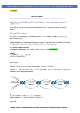
Summarization of Routes:
Route scalability is a large factor for the IGP routing protocols used by service providers because
there can be thousands of routers running in a network.
Before Summarization:
MUMBAIR6(config-if)#do sh ip rout | i 192.
O IA 192.168.23.0/24 [110/20] via 10.100.100.1, 00:00:17, Ethernet0/0
192.168.24.0/32 is subnetted, 1 subnets
O IA 192.168.24.1 [110/21] via 10.100.100.1, 00:00:17, Ethernet0/0
192.168.25.0/32 is subnetted, 1 subnets
O IA 192.168.25.1 [110/21] via 10.100.100.1, 00:00:17, Ethernet0/0
192.168.26.0/32 is subnetted, 1 subnets
O IA 192.168.26.1 [110/21] via 10.100.100.1, 00:00:17, Ethernet0/0
CONFIG:
MUMBAIR2(config)#
interface Loopback24
ip address 192.168.24.1 255.255.255.0
end
interface Loopback25
ip address 192.168.25.1 255.255.255.0
end
interface Loopback26
ip address 192.168.26.1 255.255.255.0
end
MUMBAIR2(config)#
router ospf 100
network 192.168.24.0 0.0.0.255 area 0
network 192.168.25.0 0.0.0.255 area 0
network 192.168.26.0 0.0.0.255 area 0
Summarization is enabled always on ABR only
MUMBAIR4(config)#
router ospf 1
area 0 range 192.168.0.0 255.255.0.0 cost 11
After Summarization:
MUMBAIR6(config-if)#do sh ip rout | begin 192.
O IA 192.168.0.0/16 [110/21] via 10.100.100.1, 00:01:14, Ethernet0/0](https://image.slidesharecdn.com/3iprouting-pbrbfd-v2-200820144352/85/3-ip-routing-pbr-bfd-v2-57-320.jpg)
![TRAINER: SAGAR | NetworkJourney.com | www.youtube.com/c/NetworkJourney | LinkedIN
CCNP ENTERPRISE 2020 LAB WORKBOOK|| TRAINER: SAGAR || WWW.YOUTUBE.COM/C/NETWORKJOURNEY
router-id 192.168.2.2
network 10.12.1.0 0.0.0.255 area 12
network 10.23.1.0 0.0.0.255 area 0
area 0 filter-list prefix PREFIX-FILTER in
RESULT:
R3# show ip route ospf | begin Gateway
Gateway of last resort is not set
10.0.0.0/8 is variably subnetted, 5 subnets, 2 masks
O IA 10.12.1.0/24 [110/2] via 10.23.1.2, 00:17:39, GigabitEthernet0/1
172.16.0.0/24 is subnetted, 2 subnets
O IA 172.16.2.0 [110/3] via 10.23.1.2, 00:16:30, GigabitEthernet0/1
O IA 172.16.3.0 [110/3] via 10.23.1.2, 00:16:30, GigabitEthernet0/1
MUMBAIR4(config)#
ip prefix-list PREFIX-FILTER seq 5 deny 192.168.24.1/32
ip prefix-list PREFIX-FILTER seq 10 permit 192.168.0.0/16
router ospf 1
area 40 filter-list prefix PREFIX-FILTER in
MUMBAIR6# sh ip rout | i 192.168.24.
MUMBAIR6# -> NO ROUTES FOUND FOR 192.168.24.
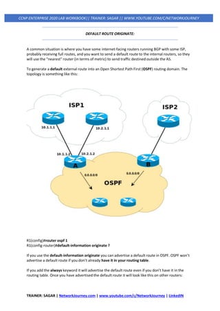
Local OSPF Filtering
In some scenarios, routes need to be removed only on specific routers in an area.
OSPF is a link-state protocol that requires all routers in the same area to maintain an identical copy
of the LSDB for that area.
A route can exist in the OSPF LSDB, but it could be prevented from being installed in the local RIB.
This is accomplished by using a Distribute List.
MUMBAIR4(config)#
MUMBAIR4(config)#ip access-list standard ACL-OSPF
MUMBAIR4(config-std-nacl)#10 deny 192.168.24.0 0.0.0.255
MUMBAIR4(config-std-nacl)#20 permit any
router ospf 1
distribute-list ACL-OSPF in
MUMBAIR6# sh ip rout | i 192.168.24
192.168.24.0/32 is subnetted, 1 subnets
O IA 192.168.24.1 [110/21] via 10.100.100.1, 00:09:02, Ethernet0/0
MUMBAIR6#
Route will be present but no reachability
MUMBAIR6#ping 192.168.24.1
Type escape sequence to abort.
Sending 5, 100-byte ICMP Echos to 192.168.24.1, timeout is 2 seconds:
UUUUU](https://image.slidesharecdn.com/3iprouting-pbrbfd-v2-200820144352/85/3-ip-routing-pbr-bfd-v2-59-320.jpg)
![TRAINER: SAGAR | NetworkJourney.com | www.youtube.com/c/NetworkJourney | LinkedIN
CCNP ENTERPRISE 2020 LAB WORKBOOK|| TRAINER: SAGAR || WWW.YOUTUBE.COM/C/NETWORKJOURNEY
MUMBAIR6#show ip ospf database | begin Type-5
Type-5 AS External Link States
Link ID ADV Router Age Seq# Checksum Tag
0.0.0.0 172.16.3.1 59 0x80000001 0x008D64 1
MUMBAIR6#show ip route ospf
O*E2 0.0.0.0/0 [110/1] via 192.168.12.1, 00:00:24, FastEthernet0/0
EXAMPLE:
MUMBAIR6
hostname MUMBAIR6
!
interface FastEthernet0/1
ip address 192.168.12.1 255.255.255.0
!
router ospf 1
network 192.168.12.0
default-information originate always
!
end
VIRTUAL LINKS:
All areas in an Open Shortest Path First (OSPF) autonomous system must be physically
connected to the backbone area (Area 0). In some cases, where this is not possible, you can
use a virtual link to connect to the backbone through a non-backbone area.
You can also use virtual links to connect two parts of a partitioned backbone through a non-
backbone area.
The area through which you configure the virtual link, known as a transit area, must have
full routing information.
The transit area cannot be a stub area.
router ospf 1
area 1 virtual-link 3.3.3.3
router ospf 1
area 1 virtual-link 1.1.1.1
show ip ospf virtual-links
Router3.3.3.3#show ip ospf neighbor](https://image.slidesharecdn.com/3iprouting-pbrbfd-v2-200820144352/85/3-ip-routing-pbr-bfd-v2-61-320.jpg)
![TRAINER: SAGAR | NetworkJourney.com | www.youtube.com/c/NetworkJourney | LinkedIN
CCNP ENTERPRISE 2020 LAB WORKBOOK|| TRAINER: SAGAR || WWW.YOUTUBE.COM/C/NETWORKJOURNEY
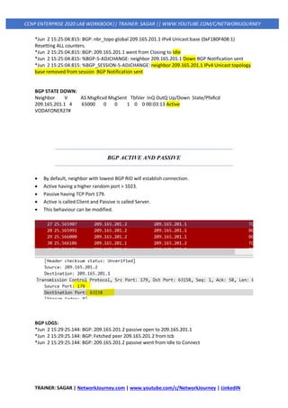
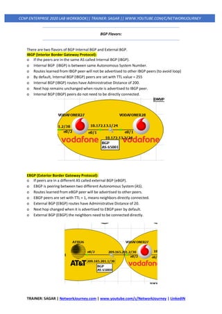
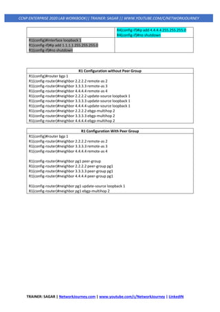
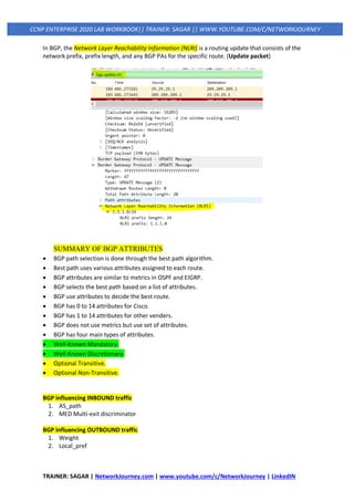
Metric BGP attributes that are used to select the best path
LocPrf BGP attributes that are used to select the best path
Weight BGP attributes that are used to select the best path
Path A sequence of Autonomous Systems in the path from Left to Right
Path i Network was advertised using the network command
Path 2 AS path 2
Path ? Redistributed Networks
Weight = 32768 for LOCAL
Weight = 0 other routes
ROUTING TABLE:
ATT26#show ip route
<!—output omitted--!>
Gateway of last resort is not set
29.0.0.0/24 is subnetted, 1 subnets
B 29.29.29.0 [20/0] via 209.165.201.2, 00:15:17
209.165.201.0/24 is variably subnetted, 2 subnets, 2 masks
<!—output omitted--!>
B This route was learned through BGP
29.29.29.0/24 Destination learn network and 24 is subnet mask
20 20 is the Administrative Distance of eBGP protocol
209.165.201.2 Next Hop IP Address where to send the traffic
00:15:17 Time since the route was learnt
DEBUG:
debug ip bgp all
debug ip bgp ipv4 unicast updates
VODAFONER27#
*Jun 2 15:25:04.814: BGP: 209.165.201.1 connection timed out 180187ms (last update) 180000ms
(hold time)
*Jun 2 15:25:04.814: BGP: 209.165.201.1 went from Established to Closing
*Jun 2 15:25:04.814: %BGP-3-NOTIFICATION: sent to neighbor 209.165.201.1 4/0 (hold time
expired) 0 bytes
*Jun 2 15:25:04.814: BGP: ses global 209.165.201.1 (0xF1B0F408:1) Send NOTIFICATION 4/0 (hold
time expired) 0 bytes
*Jun 2 15:25:04.814: BGP: 209.165.201.1 local error close after sending NOTIFICATION
*Jun 2 15:25:04.814: %BGP-5-NBR_RESET: Neighbor 209.165.201.1 reset (BGP Notification sent)
*Jun 2 15:25:04.814: BGP: nbr_topo global 209.165.201.1 IPv4 Unicast:base (0xF1B0F408:1) NSF
delete stale NSF not active
*Jun 2 15:25:04.815: BGP: 209.165.201.1 closing
*Jun 2 15:25:04.815: BGP: ses global 209.165.201.1 (0xF1B0F408:1) Session close and reset
neighbor 209.165.201.1 topostate](https://image.slidesharecdn.com/3iprouting-pbrbfd-v2-200820144352/85/3-ip-routing-pbr-bfd-v2-74-320.jpg)
![TRAINER: SAGAR | NetworkJourney.com | www.youtube.com/c/NetworkJourney | LinkedIN
CCNP ENTERPRISE 2020 LAB WORKBOOK|| TRAINER: SAGAR || WWW.YOUTUBE.COM/C/NETWORKJOURNEY
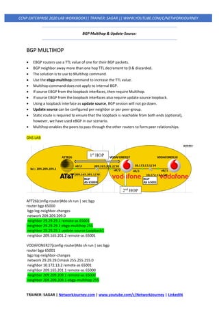
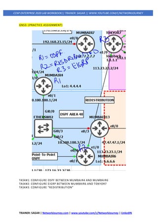
GNS3:
CE1(config)#
router bgp 1
bgp default local-preference 150
OR
CE1(config)#
neighbor 10.1.2.2 route-map in
route-map LOCAL-PREF-150
set local-preference 150
Clear ip bgp *
Or
Clear ip bgp 10.1.2.2 soft (preferable) [keeps the tcp session, only refreshes route changes]
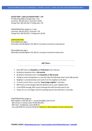
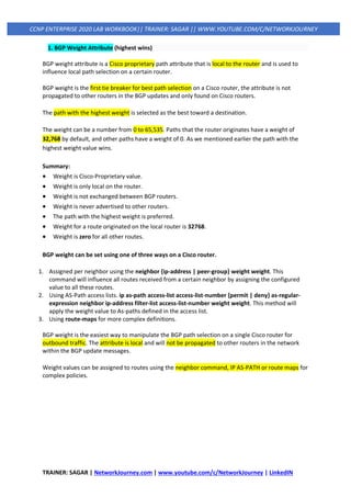
SHOW COMMANDS:
1st
Method to Verify:
CORE#sh ip bgp 8.8.8.8 bestpath
BGP routing table entry for 8.8.8.0/24, version 51
Paths: (2 available, best #2, table default)
Not advertised to any peer
Refresh Epoch 1
2 4 5
192.168.12.2 from 192.168.12.2 (192.168.14.1)
Origin IGP, metric 0, localpref 250, valid, internal, best
rx pathid: 0, tx pathid: 0x0
2nd
Method to Verify:
CORE#sh ip bgp
<!output omitted--!>
Network Next Hop Metric LocPrf Weight Path
* i 8.8.8.0/24 192.168.13.2 0 150 0 3 4 5 i
*>i 192.168.12.2 0 250 0 2 4 5 i
3rd
Method to Verify:
CORE#traceroute 8.8.8.8
Type escape sequence to abort.
Tracing the route to 8.8.8.8
VRF info: (vrf in name/id, vrf out name/id)](https://image.slidesharecdn.com/3iprouting-pbrbfd-v2-200820144352/85/3-ip-routing-pbr-bfd-v2-92-320.jpg)
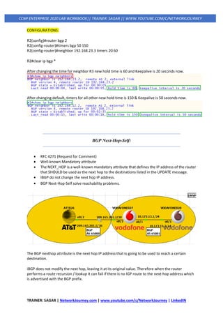
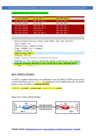
![TRAINER: SAGAR | NetworkJourney.com | www.youtube.com/c/NetworkJourney | LinkedIN
CCNP ENTERPRISE 2020 LAB WORKBOOK|| TRAINER: SAGAR || WWW.YOUTUBE.COM/C/NETWORKJOURNEY
1 192.168.12.2 0 msec 1 msec 0 msec
2 10.1.2.2 1 msec 1 msec 1 msec
3 10.2.4.2 [AS 2] 1 msec 1 msec 1 msec
4 192.168.102.2 [AS 4] 1 msec 0 msec 0 msec
5 10.4.5.2 [AS 4] 2 msec 1 msec 1 msec
If you see the local preference attribute has been applied to all routes coming in from PE1, if
we just wanted to do it for 8.8.8.8 then we could match this network in a prefix-list and add
that to the route-map.
ip prefix-list 8.8.8.8 seq 5 permit 8.8.8.8/32
route-map LOCAL-PREF-150 permit 10
match ip address prefix-list 8.8.8.8
set local-preference 150
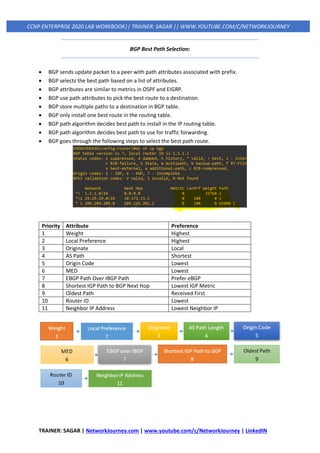
4. AS Path:
o AS Path is the fourth BGP attribute.
o AS path is a mandatory attribute, describe path taken on the way to destination.
o BGP prefers the shortest AS path to get to a destination.
o BGP AS Path is a Well-Known mandatory attribute.
o Ordered list of ASNs through which the update has passed.
o The main purpose of the AS Path is to avoid loops.
o AS-Path prepending is to make received prefix "Less Attractive".
o Add own AS number multiple times so the as path becomes longer.
o AS-Path prepending is a way to manipulate the AS-Path attribute of a BGP route.
o AS-Path prepending used to influence inbound direction traffic.
o AS path 1 2 3 is preferred over AS path 1 2 3 4 5.
GNS3
CE1(config)#
router bgp 1
neighbor 10.1.2.2 route-map PREPEND out
!
route-map PREPEND permit 10
set as-path prepend 40000 40000
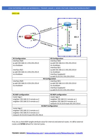
Show commands:
GOOGLE-SERVER#show ip bgp
*> 0.0.0.0 0 32768 i
*> 101.101.101.0/24 10.4.5.1 0 4 3 1 i
*> 192.168.12.0 10.4.5.1 0 4 2 1 40000 40000 i
*> 192.168.13.0 10.4.5.1 0 4 3 1 i
*> 192.168.14.0 10.4.5.1 0 4 3 1 i
*> 192.168.102.0 10.4.5.1 0 0 4 i
*> 192.168.103.0 10.4.5.1 0 0 4 i
Network Next Hop Metric LocPrf Weight Path
*> 192.168.104.0 10.4.5.1 0 4 i](https://image.slidesharecdn.com/3iprouting-pbrbfd-v2-200820144352/85/3-ip-routing-pbr-bfd-v2-93-320.jpg)
![TRAINER: SAGAR | NetworkJourney.com | www.youtube.com/c/NetworkJourney | LinkedIN
CCNP ENTERPRISE 2020 LAB WORKBOOK|| TRAINER: SAGAR || WWW.YOUTUBE.COM/C/NETWORKJOURNEY
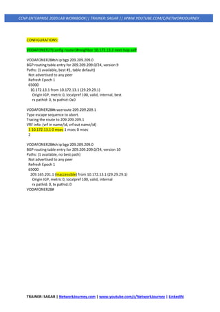
PROTOCOL-SPECIFIC CONFIGURATION
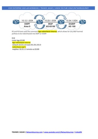
redistribute {connected | static | eigrp as-number | ospf process-id [match
{internal | external [1|2]}] | bgp as-number} [destination-protocol-
options] [route-map route-map-name].
Redistribution commonly uses route maps to manipulate or filter routes on the redistributing
router.
SELECTIVE REDISTRIBUTION:
BGP is designed to handle a large routing table, whereas IGPs are not. Redistributing BGP into an IGP
on a router with a larger BGP table (for example, the Internet table with 800,000+ routes) should use
selective route redistribution. Otherwise, the IGP can become unstable in the routing domain, which
can lead to packet loss.
PROTCOL BASIS REDISTRIBUTIONS:
1. EIGRP
redistribute source-protocol [metric bandwidth delay reliability
load mtu] [route-map route-map-name]
EXAMPLE1: (USING DEFAULT-METRIC)
router eigrp 100
default-metric 1000000 1 255 1 1500
network 10.23.1.0 0.0.0.255
redistribute ospf 1
EXAMPLE2: (USING LEGACY METHOD)
router eigrp 100
network 10.23.1.0 0.0.0.255
redistribute ospf 11000000 1 255 1 1500
EXAMPLE3: (USING ROUTE-MAP)
router eigrp 100
network 10.23.1.0 0.0.0.255
redistribute ospf 1 route-map OSPF-2-EIGRP
!
route-map OSPF-2-EIGRP permit 10
set metric 1000000 1 255 1 1500](https://image.slidesharecdn.com/3iprouting-pbrbfd-v2-200820144352/85/3-ip-routing-pbr-bfd-v2-102-320.jpg)
![TRAINER: SAGAR | NetworkJourney.com | www.youtube.com/c/NetworkJourney | LinkedIN
CCNP ENTERPRISE 2020 LAB WORKBOOK|| TRAINER: SAGAR || WWW.YOUTUBE.COM/C/NETWORKJOURNEY
2. OSPF
redistribute source-protocol [subnets] [metric metric] [metric-type {1 | 2}]
[tag 0-4294967295] [route-map route-map-name]
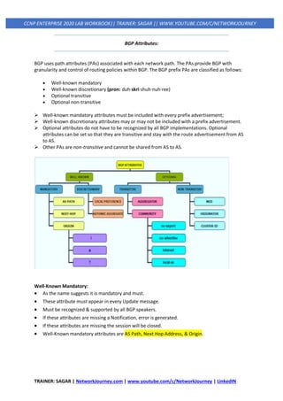
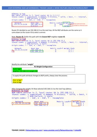
3. BGP
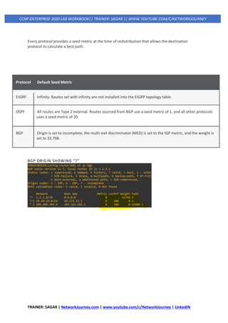
Redistributing routes into BGP does not require a seed metric because BGP is a path vector protocol.
Redistributed routes have the following BGP attributes set:
• The origin is set to incomplete.
• The next-hop address is set to the IP address of the source protocol.
• The weight is set to 32,768.
• The MED is set to the path metric of the source protocol.](https://image.slidesharecdn.com/3iprouting-pbrbfd-v2-200820144352/85/3-ip-routing-pbr-bfd-v2-103-320.jpg)
![TRAINER: SAGAR | NetworkJourney.com | www.youtube.com/c/NetworkJourney | LinkedIN
CCNP ENTERPRISE 2020 LAB WORKBOOK|| TRAINER: SAGAR || WWW.YOUTUBE.COM/C/NETWORKJOURNEY
ISSUES OF REDISTRIBUTIONS:
• Suboptimal routing
• Routing loops
PROBLEM: [Suboptimal routing]
When redistributing routes from one routing source into another routing source, the original
routing source’s information is lost when the seed metric is injected at the redistribution point.
Therefore, overall network visibility is lost or hidden from the destination routing source.
This is not an issue when there is only one point of redistribution between two sources. However, if
there are multiple points of redistribution between two sources.
SOLUTION:
You can solve this issue by providing different seed metrics on the boundary routers
PROBLEM: [Routing Loops]
Routing loops caused due to administrative distance (AD)
OSPF E2
SOLUTION:
To redistribute a route from one routing source to another (EIGRP into OSPF, for example), that
route must be in the routing table as an entry for the routing source that you are redistributing the
route from.
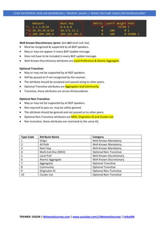
QUIZ: PART 1
1. R1 learns the 10.11.11.0/24 prefix from EIGRP. EIGRP is redistributed into OSPF on R1, and OSPF is
redistributed into BGP on R1. R1 advertises all the BGP network prefixes to R3. Does R3 receive the
10.11.11.0/24 prefix?](https://image.slidesharecdn.com/3iprouting-pbrbfd-v2-200820144352/85/3-ip-routing-pbr-bfd-v2-107-320.jpg)

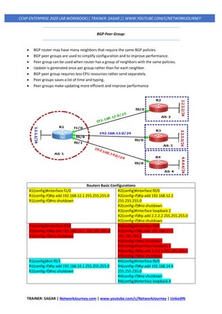
![TRAINER: SAGAR | NetworkJourney.com | www.youtube.com/c/NetworkJourney | LinkedIN
CCNP ENTERPRISE 2020 LAB WORKBOOK|| TRAINER: SAGAR || WWW.YOUTUBE.COM/C/NETWORKJOURNEY
Now let’s say that I want to use the link in between TOKYOR7 and TOKYOR12 to reach 4.4.4.4. I
could influence the metric for OSPF, but this applies to all traffic. What if I wanted to use this link for
certain traffic only?
TOKYOR7(config)#
int e0/3
ip ospf cost 1000
end
All traffic is impact due to manipulating the OSPF COST on TOKYOR7_E0/3. The route is removed
from RIB as well:
TOKYOR7#show ip route 4.4.4.4
Routing entry for 4.4.4.4/32
Known via "ospf 1", distance 110, metric 21, type intra area
Last update from 192.168.40.2 on Ethernet0/2, 00:06:41 ago
Routing Descriptor Blocks:
* 192.168.40.2, from 4.4.4.4, 00:06:41 ago, via Ethernet0/2
Route metric is 21, traffic share count is 1
192.168.10.2, from 4.4.4.4, 00:06:41 ago, via Ethernet0/1
Route metric is 21, traffic share count is 1
We could use the link in between TOKYOR7 / TOKYOR10 & TOKYOR29 for the majority of our traffic
and use the link between TOKYOR7/ TOKYOR12 only for certain traffic. This can be very useful. For
example, imagine that the link between TOKYOR7/ TOKYOR12 is a dedicated link that offers QoS for
VoIP traffic.
This is something we can achieve with PBR (Policy Based Routing) Let me show you how!
Right now, all traffic is sent towards TOKYOR29/ TOKYOR10:
TOKYOR7#show ip route | include 4.4.4.4
O 4.4.4.4 [110/21] via 192.168.40.2, 00:09:01, Ethernet0/2
TOKYOR7#show ip route 4.4.4.4
Routing Descriptor Blocks:
* 192.168.40.2, from 4.4.4.4, 00:06:41 ago, via Ethernet0/2
Route metric is 21, traffic share count is 1
192.168.10.2, from 4.4.4.4, 00:06:41 ago, via Ethernet0/1
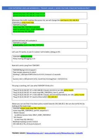
Now let’s say that we want all ICMP traffic from TOKYOR7 destined for 4.4.4.4 to cross the link
between TOKYOR7/TOKYOR12. Here’s how to do this:
First, I create an access-list that matches my traffic. Now we have to create a route-map:
TOKYOR7(config)#
ip access-list extended ONLY_ICMP_TOKYOR12
permit icmp host 192.168.10.1 host 4.4.4.4](https://image.slidesharecdn.com/3iprouting-pbrbfd-v2-200820144352/85/3-ip-routing-pbr-bfd-v2-115-320.jpg)