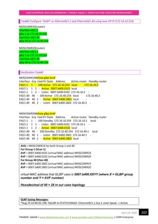
The document provides configuration instructions for Lab 1 tasks on switches SCOTSW01 through SCOTSW08. The tasks include defining hostnames, creating VLANs 99-120 and 666-999, suspending VLAN 999, creating a management interface on VLAN 99, and enabling Telnet and SSH access for the "admin" user. Users are instructed to configure these items on each switch as per the topology, using the provided configuration examples.

![TRAINER: SAGAR | www.NetworkJourney.com | www.youtube.com/c/NetworkJourney | CCNP Enterprise
CCNP ENTERPRISE 2020 LAB WORKBOOK|| TRAINER: SAGAR || WWW.YOUTUBE.COM/C/NETWORKJOURNEY
7April 24, 2020
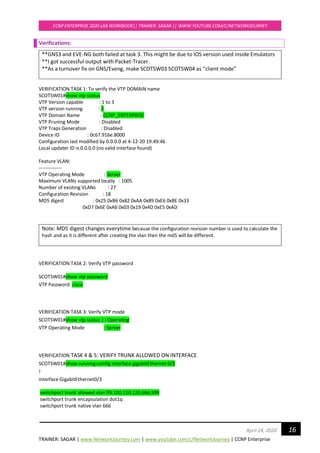
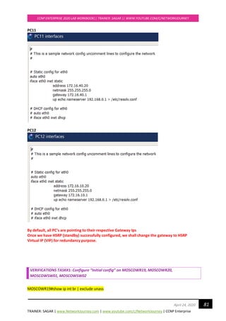
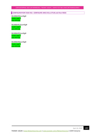
Device Initial Configuration -Switches
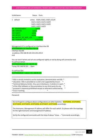
To make switches usable for new/next labs.
If incase there are vlans or configs already present in the switches, clear all the configurations to
have brand new switch for your new/next lab.
Switch#erase /all nvram:
Erasing the nvram filesystem will remove all files! Continue? [confirm]
[OK]
Erase of nvram: complete
Switch#
Switch#reload
Proceed with reload? [confirm]
This will clear all the previous configs on the switch.](https://image.slidesharecdn.com/ccnpenterpriseworkbookv1-201010132734/85/Ccnp-enterprise-workbook-v1-0-completed-till-weigth-7-320.jpg)
![TRAINER: SAGAR | www.NetworkJourney.com | www.youtube.com/c/NetworkJourney | CCNP Enterprise
CCNP ENTERPRISE 2020 LAB WORKBOOK|| TRAINER: SAGAR || WWW.YOUTUBE.COM/C/NETWORKJOURNEY
20April 24, 2020
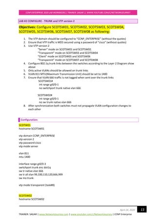
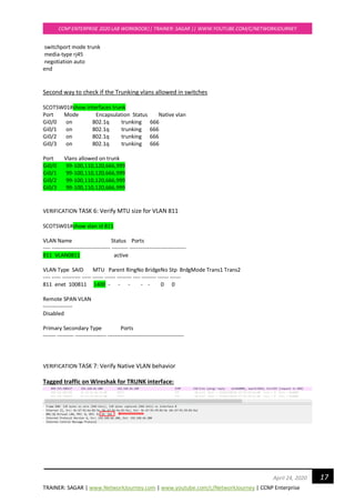
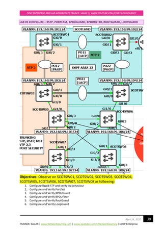
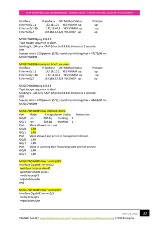
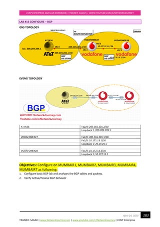
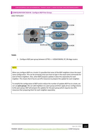
3. Configure VTP version 3 on below switches
“Primary Server” mode on SCOTSW01
“Transparent” mode on SCOTSW03
"Server" mode on SCOTSW05
"Client" mode on SCOTSW07
4. Configure 802.1q trunk links between the switches according to the Layer 2 Diagram show
above, this is already done from Lab#2, goto next Task#5
5. Create new Vlan 444 and see the VTP 3 and VTP 2 advertisements on the borders.
Configuration:
SCOTW01
vtp version 3
SCOTSW01#vtp primary vlan [to be configured on user privilege mode]
This system is becoming primary server for feature vlan
No conflicting VTP3 devices found.
Do you want to continue? [confirm]
!
Vlan 444
exit
!
SCOTW03
SCOTSW03(config)#vtp version 3
SCOTSW03(config)#vtp mode transparent
SCOTW05
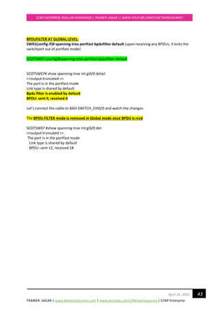
SCOTSW05(config)#vtp version 3
SCOTSW05(config)#vtp mode server
SCOTW07
SCOTSW07(config)#vtp version 3
SCOTSW07(config)#vtp mode client
Answer for #4
SCOTW01
!
Vlan 444
exit
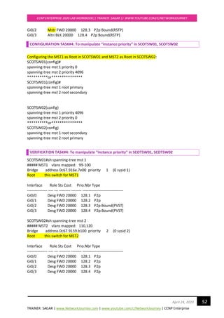
!](https://image.slidesharecdn.com/ccnpenterpriseworkbookv1-201010132734/85/Ccnp-enterprise-workbook-v1-0-completed-till-weigth-20-320.jpg)
![TRAINER: SAGAR | www.NetworkJourney.com | www.youtube.com/c/NetworkJourney | CCNP Enterprise
CCNP ENTERPRISE 2020 LAB WORKBOOK|| TRAINER: SAGAR || WWW.YOUTUBE.COM/C/NETWORKJOURNEY
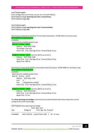
29April 24, 2020
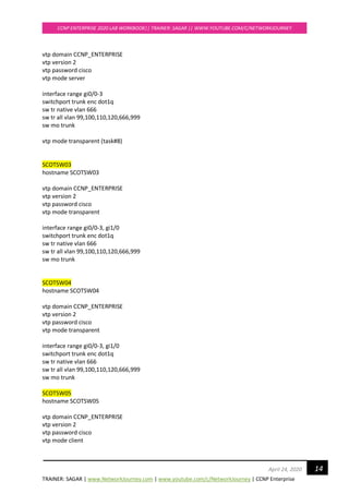
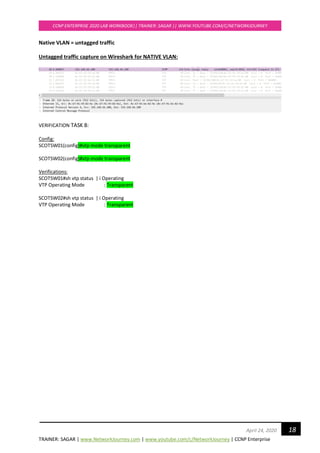
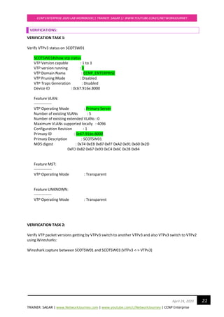
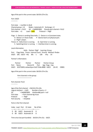
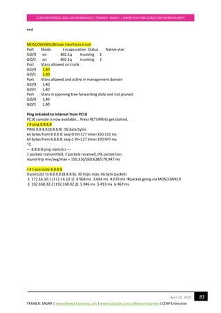
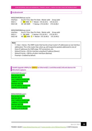
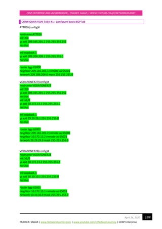
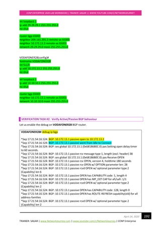
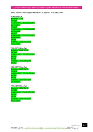
Verifications:
Examine Re-convergence Time:
Enable Debug STP command to see the convergence timers
SCOTTSW03#debug spanning-tree events
SCOTTSW03#
*Apr 20 13:13:57.732: STP: VLAN0001 Gi0/2 -> listening
*Apr 20 13:13:58.090: STP: VLAN0001 heard root 24577-0c67.916e.7e00 on Gi0/2
*Apr 20 13:13:58.091: supersedes 32769-0c67.9114.be00
*Apr 20 13:14:12.731: STP: VLAN0001 Gi0/2 -> learning
*Apr 20 13:14:27.738: STP[1]: Generating TC trap for port GigabitEthernet0/2
*Apr 20 13:14:27.740: STP: VLAN0001 sent Topology Change Notice on Gi0/2
*Apr 20 13:14:27.740: STP: VLAN0001 Gi0/2 -> forwarding
*Apr 20 13:14:29.156: STP: VLAN0001 Topology Change rcvd on Gi0/0
*Apr 20 13:14:29.158: STP: VLAN0001 sent Topology Change Notice on Gi0/2](https://image.slidesharecdn.com/ccnpenterpriseworkbookv1-201010132734/85/Ccnp-enterprise-workbook-v1-0-completed-till-weigth-29-320.jpg)
![TRAINER: SAGAR | www.NetworkJourney.com | www.youtube.com/c/NetworkJourney | CCNP Enterprise
CCNP ENTERPRISE 2020 LAB WORKBOOK|| TRAINER: SAGAR || WWW.YOUTUBE.COM/C/NETWORKJOURNEY
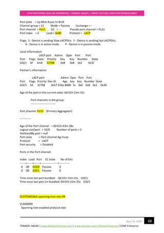
31April 24, 2020
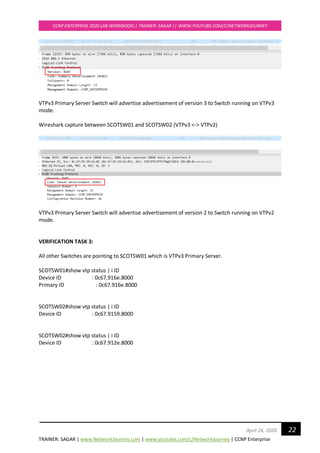
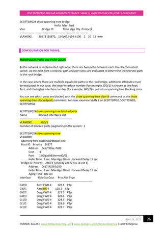
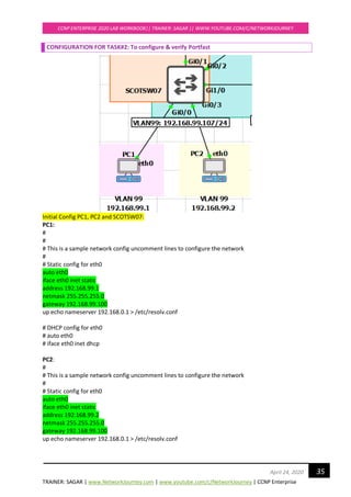
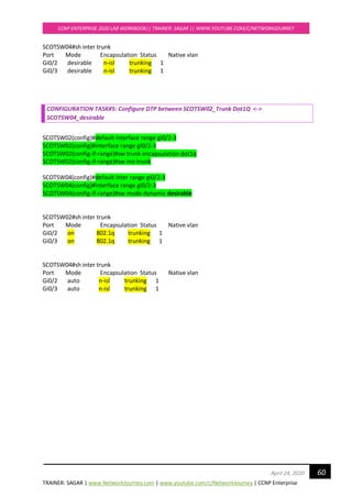
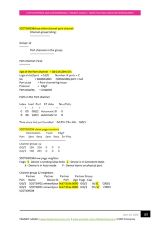
CONFIGURATION FOR TASK#1:
RSTP is backward compatible with legacy STP 802.1D
Enable RSTP on all switches:
SCOTSW01(config)#spanning-tree mode rapid-pvst
SCOTSW01(config)#end
SCOTSW02(config)#spanning-tree mode rapid-pvst
SCOTSW02(config)#end
SCOTSW03(config)#spanning-tree mode rapid-pvst
SCOTSW03(config)#end
SCOTSW04(config)#spanning-tree mode rapid-pvst
SCOTSW04(config)#end
SCOTSW05(config)#spanning-tree mode rapid-pvst
SCOTSW05(config)#end
SCOTSW06(config)#spanning-tree mode rapid-pvst
SCOTSW06(config)#end
SCOTSW07(config)#spanning-tree mode rapid-pvst
SCOTSW07(config)#end
SCOTSW08(config)#spanning-tree mode rapid-pvst
SCOTSW08(config)#end
Upon activating RSTP on every switch, you can see “proposal” and “agreements”
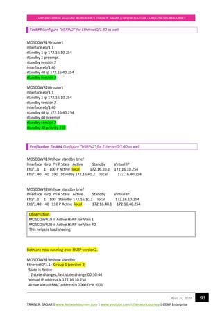
To enable debug for rstp
SCOTSW01#debug spanning-tree events
Debug Packets for RSTP on Root Bridge Switch
*Apr 21 20:46:00.427: RSTP(1): Gi2/2 fdwhile Expired
*Apr 21 20:46:00.445: STP[1]: Generating TC trap for port GigabitEthernet1/1
*Apr 21 20:46:00.446: STP[1]: Generating TC trap for port GigabitEthernet1/2
*Apr 21 20:46:00.447: STP[1]: Generating TC trap for port GigabitEthernet1/3
*Apr 21 20:46:00.505: RSTP(1): transmitting a proposal on Gi2/3
*Apr 21 20:46:00.506: RSTP(1): Gi2/3 fdwhile Expired
*Apr 21 20:46:00.509: RSTP(1): transmitting a proposal on Gi3/0
*Apr 21 20:46:00.512: RSTP(1): transmitting a proposal on Gi3/1
*Apr 21 20:46:00.515: RSTP(1): transmitting a proposal on Gi3/2
*Apr 21 20:46:00.519: RSTP(1): transmitting a proposal on Gi3/3
Debug Packets for RSTP on Non Root-bridge switch
*Apr 21 20:49:38.033: RSTP(1): Gi0/2 rcvd info expired
*Apr 21 20:49:38.033: RSTP(1): Gi0/2 is now designated](https://image.slidesharecdn.com/ccnpenterpriseworkbookv1-201010132734/85/Ccnp-enterprise-workbook-v1-0-completed-till-weigth-31-320.jpg)
![TRAINER: SAGAR | www.NetworkJourney.com | www.youtube.com/c/NetworkJourney | CCNP Enterprise
CCNP ENTERPRISE 2020 LAB WORKBOOK|| TRAINER: SAGAR || WWW.YOUTUBE.COM/C/NETWORKJOURNEY
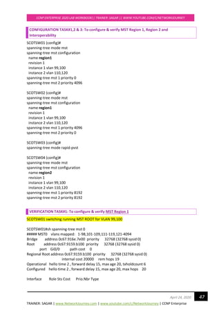
48April 24, 2020
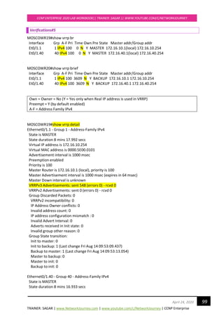
---------------- ---- --- --------- -------- --------------------------------
Gi0/0 Root FWD 20000 128.1 P2p
Gi0/1 Altn BLK 20000 128.2 P2p
Gi0/2 Desg FWD 20000 128.3 P2p Bound(PVST)
Gi0/3 Desg FWD 20000 128.4 P2p Bound(PVST)
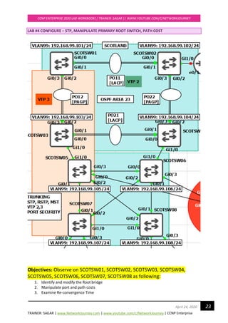
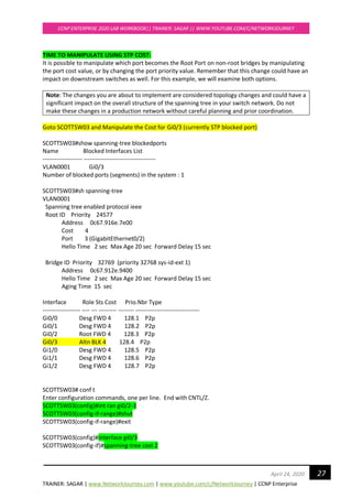
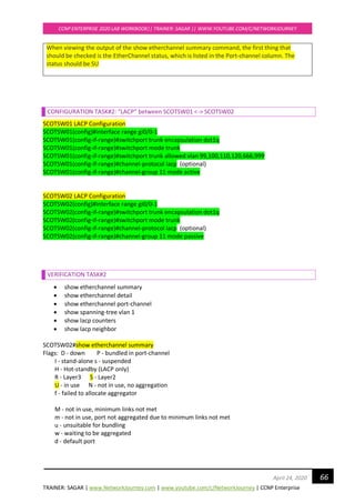
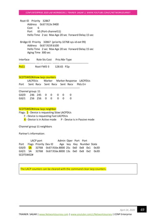
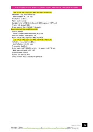
SCOTSW01#sh spanning-tree mst 1
##### MST1 vlans mapped: 99-100
Bridge address 0c67.916e.7e00 priority 1 (0 sysid 1)
Root this switch for MST1
Interface Role Sts Cost Prio.Nbr Type
---------------- ---- --- --------- -------- --------------------------------
Gi0/0 Desg FWD 20000 128.1 P2p
Gi0/1 Desg FWD 20000 128.2 P2p
Gi0/2 Desg FWD 20000 128.3 P2p Bound(PVST)
Gi0/3 Desg FWD 20000 128.4 P2p Bound(PVST)
SCOTSW01#sh spanning-tree mst 2
##### MST2 vlans mapped: 110,120
Bridge address 0c67.916e.7e00 priority 4098 (4096 sysid 2)
Root address 0c67.9159.b100 priority 2 (0 sysid 2)
port Gi0/0 cost 20000 rem hops 19
Interface Role Sts Cost Prio.Nbr Type
---------------- ---- --- --------- -------- --------------------------------
Gi0/0 Root FWD 20000 128.1 P2p
Gi0/1 Altn BLK 20000 128.2 P2p
Gi0/2 Desg FWD 20000 128.3 P2p Bound(PVST)
Gi0/3 Desg FWD 20000 128.4 P2p Bound(PVST)
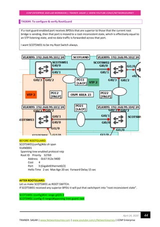
SCOTSW02 running MST ROOT for VLAN 110, 120
SCOTSW02 elected AS IST MASTER = CIST due to superior BPDU [Bridge ID = PRI+MAC ADD]
SCOTSW02#show spanning-tree mst 0
##### MST0 vlans mapped: 1-98,101-109,111-119,121-4094
Bridge address 0c67.9159.b100 priority 32768 (32768 sysid 0)
Root this switch for the CIST
Operational hello time 2 , forward delay 15, max age 20, txholdcount 6
Configured hello time 2 , forward delay 15, max age 20, max hops 20
Interface Role Sts Cost Prio.Nbr Type
---------------- ---- --- --------- -------- --------------------------------
Gi0/0 Desg FWD 20000 128.1 P2p
Gi0/1 Desg FWD 20000 128.2 P2p
Gi0/2 Desg FWD 20000 128.3 P2p
Gi0/3 Desg FWD 20000 128.4 P2p](https://image.slidesharecdn.com/ccnpenterpriseworkbookv1-201010132734/85/Ccnp-enterprise-workbook-v1-0-completed-till-weigth-48-320.jpg)


![TRAINER: SAGAR | www.NetworkJourney.com | www.youtube.com/c/NetworkJourney | CCNP Enterprise
CCNP ENTERPRISE 2020 LAB WORKBOOK|| TRAINER: SAGAR || WWW.YOUTUBE.COM/C/NETWORKJOURNEY
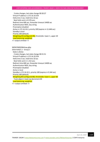
115April 24, 2020
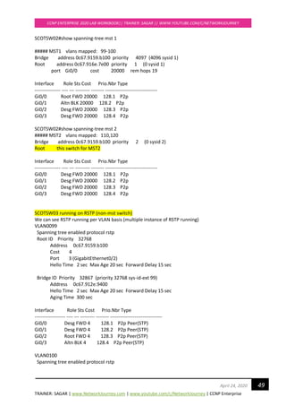
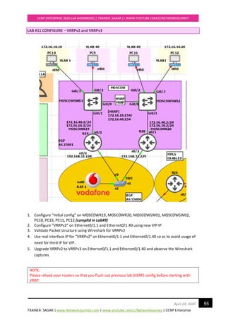
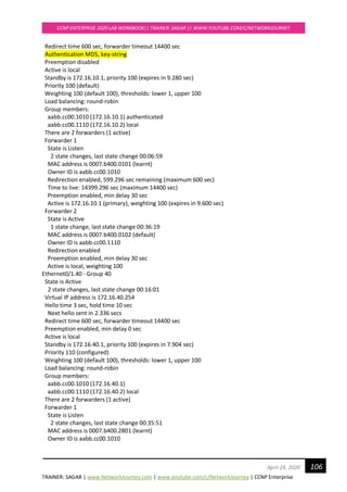
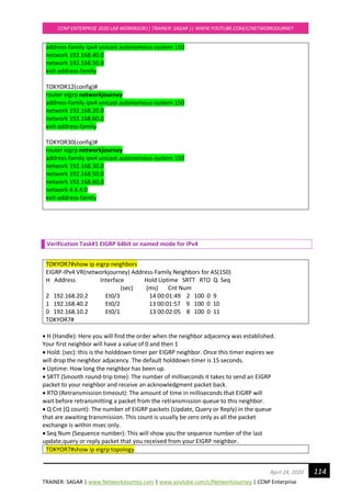
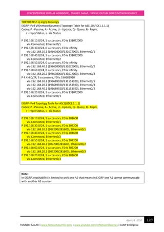
EIGRP-IPv4 VR(networkjourney) Topology Table for AS(150)/ID(1.1.1.1)
Codes: P - Passive, A - Active, U - Update, Q - Query, R - Reply,
r - reply Status, s - sia Status
P 192.168.10.0/24, 1 successors, FD is 131072000
via Connected, Ethernet0/1
P 192.168.30.0/24, 1 successors, FD is 196608000
via 192.168.10.2 (196608000/131072000), Ethernet0/1
P 192.168.40.0/24, 1 successors, FD is 131072000
via Connected, Ethernet0/2
P 192.168.50.0/24, 1 successors, FD is 196608000
via 192.168.40.2 (196608000/131072000), Ethernet0/2
P 192.168.60.0/24, 1 successors, FD is 196608000
via 192.168.20.2 (196608000/131072000), Ethernet0/3
P 4.4.4.0/24, 3 successors, FD is 196689920
via 192.168.10.2 (196689920/131153920), Ethernet0/1
via 192.168.20.2 (196689920/131153920), Ethernet0/3
via 192.168.40.2 (196689920/131153920), Ethernet0/2
P 192.168.20.0/24, 1 successors, FD is 131072000
via Connected, Ethernet0/3
• The topology table is used to store information about all known routes received from all neighbors.
If a neighbor is advertising a possible route, it must be using that route to forward packets to the
destination network.
• If the successor route goes away, DUAL will search the topology table for a backup route. The
topology table is where EIGRP stores the information for up to six alternate routes to a particular
network. The backup routes are called feasible successors.
• The feasible successors stored in the topology table are what makes it possible for EIGRP to
converge rapidly or even instantly. If there is no feasible successor in the table, a multicast is sent
out to find a new route
TOKYOR7#show ip route eigrp
Codes: L - local, C - connected, S - static, R - RIP, M - mobile, B - BGP
D - EIGRP, EX - EIGRP external, O - OSPF, IA - OSPF inter area
N1 - OSPF NSSA external type 1, N2 - OSPF NSSA external type 2
E1 - OSPF external type 1, E2 - OSPF external type 2
i - IS-IS, su - IS-IS summary, L1 - IS-IS level-1, L2 - IS-IS level-2
ia - IS-IS inter area, * - candidate default, U - per-user static route
o - ODR, P - periodic downloaded static route, H - NHRP, l - LISP
a - application route
+ - replicated route, % - next hop override
Gateway of last resort is not set
4.0.0.0/24 is subnetted, 1 subnets
D 4.4.4.0 [90/1536640] via 192.168.40.2, 00:03:17, Ethernet0/2
[90/1536640] via 192.168.20.2, 00:03:17, Ethernet0/3
[90/1536640] via 192.168.10.2, 00:03:17, Ethernet0/1
D 192.168.30.0/24 [90/1536000] via 192.168.10.2, 00:04:11, Ethernet0/1](https://image.slidesharecdn.com/ccnpenterpriseworkbookv1-201010132734/85/Ccnp-enterprise-workbook-v1-0-completed-till-weigth-115-320.jpg)
![TRAINER: SAGAR | www.NetworkJourney.com | www.youtube.com/c/NetworkJourney | CCNP Enterprise
CCNP ENTERPRISE 2020 LAB WORKBOOK|| TRAINER: SAGAR || WWW.YOUTUBE.COM/C/NETWORKJOURNEY
116April 24, 2020
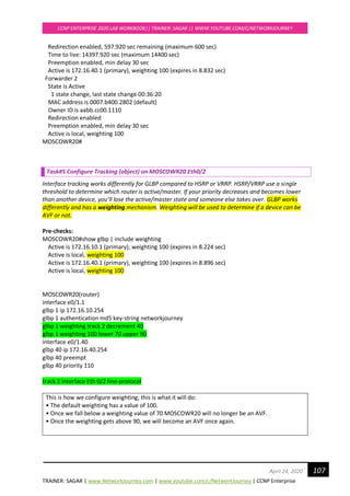
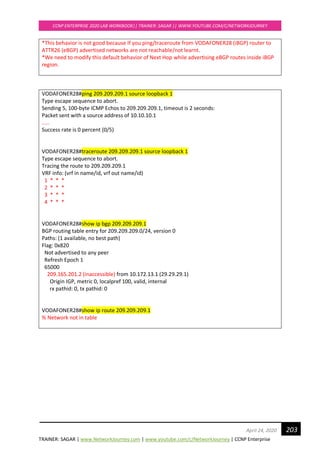
D 192.168.50.0/24 [90/1536000] via 192.168.40.2, 00:04:11, Ethernet0/2
D 192.168.60.0/24 [90/1536000] via 192.168.20.2, 00:04:11, Ethernet0/3
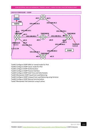
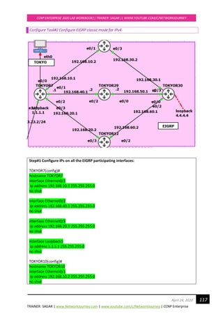
TOKYOR7#
EIGRP AD value is 90 and EIGRP routes will be represented with ‘D’ and EIGRP also installs both the
paths in routing table with equal cost for achieving equal cost load balancing.
D Shows this is an EIGRP learnt route
4.0.0.0/24 Destination learn network and 24 is subnet mask.
90 90, is the Administrative Distance of EIGRP.
1536640 This is the metric, Total distance to get to the destination
192.168.40.2 The neighbor that advertised the route.
00:03:17 Time since the route was learnt.
Ethernet0/2 The outbound interface going towards the destination.
Best path is installed in Routing Table and Backup path is installed in topology table.](https://image.slidesharecdn.com/ccnpenterpriseworkbookv1-201010132734/85/Ccnp-enterprise-workbook-v1-0-completed-till-weigth-116-320.jpg)
![TRAINER: SAGAR | www.NetworkJourney.com | www.youtube.com/c/NetworkJourney | CCNP Enterprise
CCNP ENTERPRISE 2020 LAB WORKBOOK|| TRAINER: SAGAR || WWW.YOUTUBE.COM/C/NETWORKJOURNEY
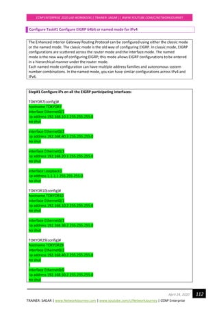
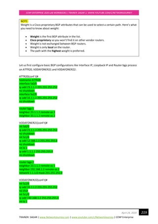
121April 24, 2020
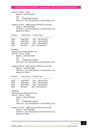
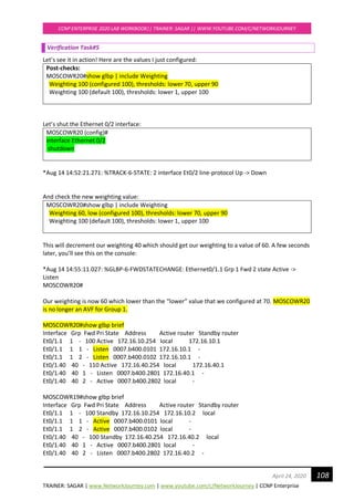
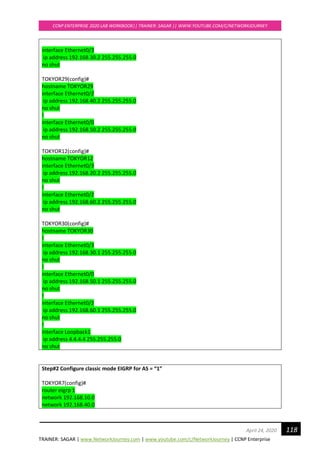
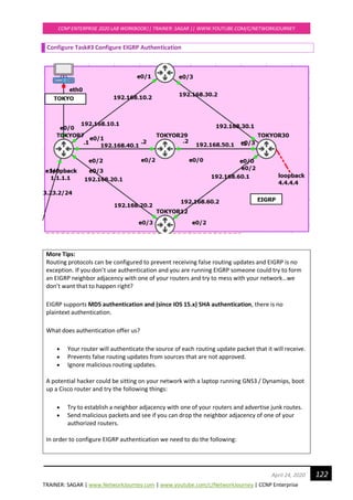
TOKYOR7#show ip route eigrp
Codes: L - local, C - connected, S - static, R - RIP, M - mobile, B - BGP
D - EIGRP, EX - EIGRP external, O - OSPF, IA - OSPF inter area
N1 - OSPF NSSA external type 1, N2 - OSPF NSSA external type 2
E1 - OSPF external type 1, E2 - OSPF external type 2
i - IS-IS, su - IS-IS summary, L1 - IS-IS level-1, L2 - IS-IS level-2
ia - IS-IS inter area, * - candidate default, U - per-user static route
o - ODR, P - periodic downloaded static route, H - NHRP, l - LISP
a - application route
+ - replicated route, % - next hop override
Gateway of last resort is not set
4.0.0.0/24 is subnetted, 1 subnets
D 4.4.4.0 [90/1536640] via 192.168.40.2, 00:17:52, Ethernet0/2
[90/1536640] via 192.168.20.2, 00:17:52, Ethernet0/3
[90/1536640] via 192.168.10.2, 00:17:52, Ethernet0/1
D 192.168.30.0/24 [90/307200] via 192.168.10.2, 00:04:56, Ethernet0/1
D 192.168.50.0/24 [90/307200] via 192.168.40.2, 00:04:56, Ethernet0/2
D 192.168.60.0/24 [90/307200] via 192.168.20.2, 00:04:56, Ethernet0/3
TOKYOR7#](https://image.slidesharecdn.com/ccnpenterpriseworkbookv1-201010132734/85/Ccnp-enterprise-workbook-v1-0-completed-till-weigth-121-320.jpg)
![TRAINER: SAGAR | www.NetworkJourney.com | www.youtube.com/c/NetworkJourney | CCNP Enterprise
CCNP ENTERPRISE 2020 LAB WORKBOOK|| TRAINER: SAGAR || WWW.YOUTUBE.COM/C/NETWORKJOURNEY
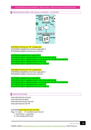
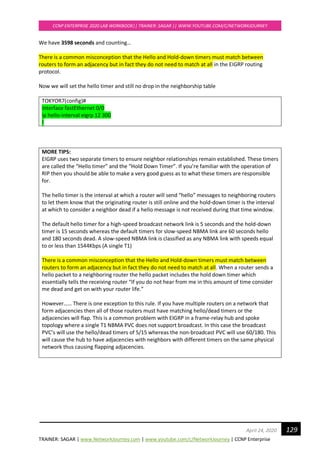
130April 24, 2020
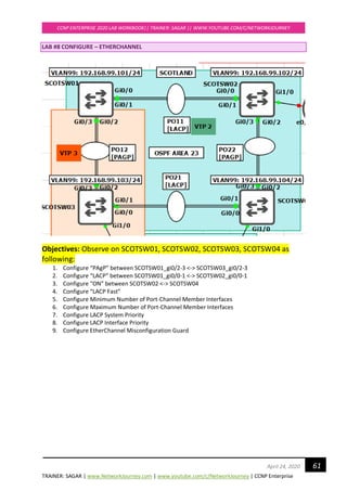
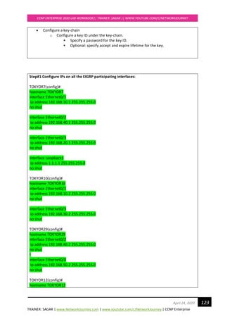
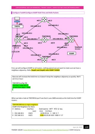
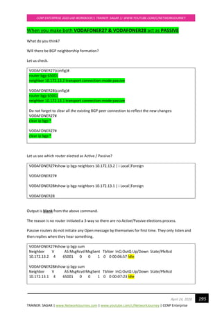
Configure Task#5 Manipulate EIGRP Equal Cost Load Balancing
NOTE:
By default, EIGRP supports equal-cost load balancing over four links. Equal-cost means that
multiple routes must have the same metric to reach a destination, so that router can choose to
load balance across equal cost links.
o EIGRP take load balancing by default up-to 4 paths can configure up to 32.
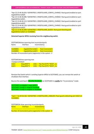
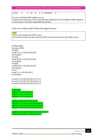
From our previous Lab config, I see destination network 4.4.4.4 has three best paths to reach from
TOKYOR7, check below:
TOKYOR7#sh ip route eigrp
Gateway of last resort is not set
4.0.0.0/24 is subnetted, 1 subnets
D 4.4.4.0 [90/435200] via 192.168.40.2, 00:47:50, Ethernet0/2
[90/435200] via 192.168.20.2, 00:47:50, Ethernet0/3
[90/435200] via 192.168.10.2, 00:47:50, Ethernet0/1
D 192.168.30.0/24 [90/307200] via 192.168.10.2, 00:47:50, Ethernet0/1
D 192.168.50.0/24 [90/307200] via 192.168.40.2, 00:47:50, Ethernet0/2
D 192.168.60.0/24 [90/307200] via 192.168.20.2, 00:47:51, Ethernet0/3](https://image.slidesharecdn.com/ccnpenterpriseworkbookv1-201010132734/85/Ccnp-enterprise-workbook-v1-0-completed-till-weigth-130-320.jpg)
![TRAINER: SAGAR | www.NetworkJourney.com | www.youtube.com/c/NetworkJourney | CCNP Enterprise
CCNP ENTERPRISE 2020 LAB WORKBOOK|| TRAINER: SAGAR || WWW.YOUTUBE.COM/C/NETWORKJOURNEY
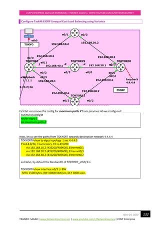
131April 24, 2020
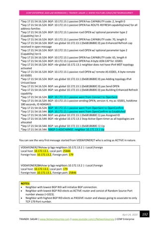
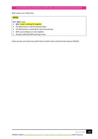
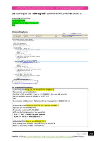
Using maximum-path router configuration command, let us configure maximum paths to be only 2.
TOKYOR7(config)#
router eigrp 1
maximum-paths 2
Now load balancing is happening between 2 paths only:
TOKYOR7#show ip rout eigrp
4.0.0.0/24 is subnetted, 1 subnets
D 4.4.4.0 [90/435200] via 192.168.20.2, 00:00:52, Ethernet0/3
[90/435200] via 192.168.10.2, 00:00:52, Ethernet0/1
D 192.168.30.0/24 [90/307200] via 192.168.10.2, 00:00:52, Ethernet0/1
D 192.168.50.0/24 [90/307200] via 192.168.40.2, 00:00:52, Ethernet0/2
D 192.168.60.0/24 [90/307200] via 192.168.20.2, 00:00:52, Ethernet0/3
TOKYOR7#show ip route 4.4.4.4
Routing entry for 4.4.4.0/24
Known via "eigrp 1", distance 90, metric 435200, type internal
Redistributing via eigrp 1
Last update from 192.168.20.2 on Ethernet0/3, 00:04:42 ago
Routing Descriptor Blocks:
192.168.20.2, from 192.168.20.2, 00:04:42 ago, via Ethernet0/3
Route metric is 435200, traffic share count is 1
Total delay is 7000 microseconds, minimum bandwidth is 10000 Kbit
Reliability 255/255, minimum MTU 1500 bytes
Loading 1/255, Hops 2
* 192.168.10.2, from 192.168.10.2, 00:04:42 ago, via Ethernet0/1
Route metric is 435200, traffic share count is 1
Total delay is 7000 microseconds, minimum bandwidth is 10000 Kbit
Reliability 255/255, minimum MTU 1500 bytes
Loading 1/255, Hops 2
NOTE:
Set maximum-path to 1 to disable load balancing.](https://image.slidesharecdn.com/ccnpenterpriseworkbookv1-201010132734/85/Ccnp-enterprise-workbook-v1-0-completed-till-weigth-131-320.jpg)
![TRAINER: SAGAR | www.NetworkJourney.com | www.youtube.com/c/NetworkJourney | CCNP Enterprise
CCNP ENTERPRISE 2020 LAB WORKBOOK|| TRAINER: SAGAR || WWW.YOUTUBE.COM/C/NETWORKJOURNEY
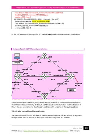
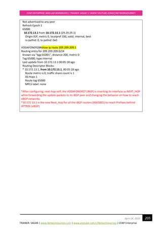
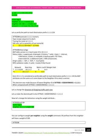
133April 24, 2020
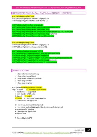
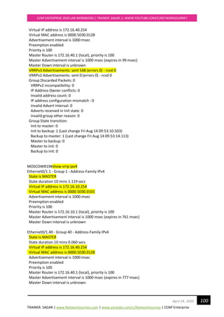
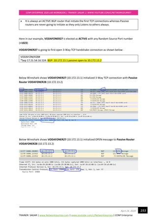
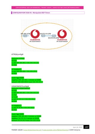
Let us decrease the bandwidth of TOKYOR7_eth0/3 and set new BW = 5000
TOKYOR7(config)#
int e0/3
bandwidth 5000
!
We know that in EIGRP the path is influenced whenever the Metric for Outgoing interfaces gets
manipulated.
We see now only two best paths to reach destination 4.4.4.4
TOKYOR7#show ip route eigrp | sec 4.4.4.0
D 4.4.4.0 [90/435200] via 192.168.40.2, 00:00:40, Ethernet0/2
[90/435200] via 192.168.10.2, 00:00:40, Ethernet0/1
However, we see all three paths (including backup path) inside EIGRP’s Topology table to reach
destination 4.4.4.4
TOKYOR7#show ip eigrp topology | sec 4.4.4.0
P 4.4.4.0/24, 2 successors, FD is 435200
via 192.168.10.2 (435200/409600), Ethernet0/1
via 192.168.40.2 (435200/409600), Ethernet0/2
via 192.168.20.2 (691200/409600), Ethernet0/3
435200 → FD Feasible Distance (local router’s metric of the best route to reach a specific
network)
409600 → AD Advertised Distance (the metric advertised by the neighbouring router for a specific
route)
691200 →FS Feasible Successor (metric for backup route)
We’ll view this topology from TOKYOR7’s perspective. Let’s fill in the successor, feasible successor,
advertised and feasible distance in a table:
Advertised Distance Feasible distance
TOKYOR10 409600 435200 SUCCESSOR
TOKYOR29 409600 435200 SUCCESSOR
TOKYOR12 409600 691200 FEASIBLE
SUCCESSOR](https://image.slidesharecdn.com/ccnpenterpriseworkbookv1-201010132734/85/Ccnp-enterprise-workbook-v1-0-completed-till-weigth-133-320.jpg)
![TRAINER: SAGAR | www.NetworkJourney.com | www.youtube.com/c/NetworkJourney | CCNP Enterprise
CCNP ENTERPRISE 2020 LAB WORKBOOK|| TRAINER: SAGAR || WWW.YOUTUBE.COM/C/NETWORKJOURNEY
134April 24, 2020
Now we are going to change things so we’ll see the feasible successor in the routing table as well so
it will load-balance.
So far so good, we found the TOKYOR10 & TOKYOR29 to be successor (435200) and we know that
TOKYOR12 is feasible successors (691200). If we want to enable load balancing, we have to use the
following formula:
FD of feasible successor < FD of successor * multiplier
You can make EIGRP to support unequal cost load-balancing by using the variance command. The
variance command works as a multiplier:
• Our successor has a feasible distance of 435200.
• Our feasible successor has a feasible distance of 691200
Variance = 691200 / 435200 = 1.588
This lab is to prove EIGRP supports unequal load-balancing.
We will configure the “variance” under EIGRP process:
TOKYOR7(config)#
router eigrp 1
variance 2
Let’s take a look at TOKYOR7 to see if this has any effect:
TOKYOR7# show ip route eigrp | sec 4.4.4.0
D 4.4.4.0 [90/435200] via 192.168.40.2, 00:00:10, Ethernet0/2
[90/691200] via 192.168.20.2, 00:00:10, Ethernet0/3
[90/435200] via 192.168.10.2, 00:00:10, Ethernet0/1
Above you can see that TOKYOR7 has installed the path through TOKYOR12 as well. EIGRP does
“unequal” cost load balancing and to see how it shares traffic among the interfaces we have to use
another command:
TOKYOR7#show ip route 4.4.4.4
Routing entry for 4.4.4.0/24
Known via "eigrp 1", distance 90, metric 435200, type internal
Redistributing via eigrp 1
Last update from 192.168.20.2 on Ethernet0/3, 00:01:20 ago
Routing Descriptor Blocks:
* 192.168.40.2, from 192.168.40.2, 00:01:20 ago, via Ethernet0/2
Route metric is 435200, traffic share count is 240
Total delay is 7000 microseconds, minimum bandwidth is 10000 Kbit
Reliability 255/255, minimum MTU 1500 bytes
Loading 1/255, Hops 2
192.168.20.2, from 192.168.20.2, 00:01:20 ago, via Ethernet0/3
Route metric is 691200, traffic share count is 151](https://image.slidesharecdn.com/ccnpenterpriseworkbookv1-201010132734/85/Ccnp-enterprise-workbook-v1-0-completed-till-weigth-134-320.jpg)
![TRAINER: SAGAR | www.NetworkJourney.com | www.youtube.com/c/NetworkJourney | CCNP Enterprise
CCNP ENTERPRISE 2020 LAB WORKBOOK|| TRAINER: SAGAR || WWW.YOUTUBE.COM/C/NETWORKJOURNEY
136April 24, 2020
The cool thing about EIGRP and manual summarization is that it’s easy to do and can be done on the
interface-level.
Let us advertise a new network 4.5.5.0/24 in TOKYOR30 which we would consider later on for
performing manual summarization:
TOKYOR30(config)#
router eigrp 1
network 4.5.5.0
!
interface loopback 2
ip add 4.5.5.1 255.255.255.0
no shut
!
Now we see the new advertised network 4.5.5.0/24 on TOKYOR7
TOKYOR7#show ip route | sec 4.0.0.0
4.0.0.0/24 is subnetted, 2 subnets
D 4.4.4.0 [90/435200] via 192.168.40.2, 00:10:11, Ethernet0/2
[90/691200] via 192.168.20.2, 00:10:11, Ethernet0/3
[90/435200] via 192.168.10.2, 00:10:11, Ethernet0/1
D 4.5.5.0 [90/435200] via 192.168.40.2, 00:00:57, Ethernet0/2
[90/691200] via 192.168.20.2, 00:00:57, Ethernet0/3
[90/435200] via 192.168.10.2, 00:00:57, Ethernet0/1
Let us manual summarize this:
In EIGRP we can summarize routes on every router that is participating in EIGRP network.
Manual summarization is configured on a per-interface basis on EIGRP.
TOKYOR7(config)#
interface e0/3
ip summary-address eigrp 1 4.0.0.0 255.0.0.0
*Aug 28 17:01:31.130: %DUAL-5-NBRCHANGE: EIGRP-IPv4 1: Neighbor 192.168.20.2
(Ethernet0/3) is resync: summary configured
Here is the summarized EIGRP routes:
TOKYOR7#show ip route | sec 4.0.0.0
4.0.0.0/8 is variably subnetted, 3 subnets, 2 masks
D 4.0.0.0/8 is a summary, 00:18:31, Null0
D 4.4.4.0/24 [90/435200] via 192.168.40.2, 01:19:33, Ethernet0/2
[90/691200] via 192.168.20.2, 01:19:33, Ethernet0/3
[90/435200] via 192.168.10.2, 01:19:33, Ethernet0/1
D 4.5.5.0/24 [90/435200] via 192.168.40.2, 01:10:19, Ethernet0/2
[90/691200] via 192.168.20.2, 01:10:19, Ethernet0/3
[90/435200] via 192.168.10.2, 01:10:19, Ethernet0/1](https://image.slidesharecdn.com/ccnpenterpriseworkbookv1-201010132734/85/Ccnp-enterprise-workbook-v1-0-completed-till-weigth-136-320.jpg)
![TRAINER: SAGAR | www.NetworkJourney.com | www.youtube.com/c/NetworkJourney | CCNP Enterprise
CCNP ENTERPRISE 2020 LAB WORKBOOK|| TRAINER: SAGAR || WWW.YOUTUBE.COM/C/NETWORKJOURNEY
138April 24, 2020
Configure Task#8 Manipulate Path Selection using K-values
NOTE:
EIGRP uses different K values to determine the best path to each destination:
K1
K2
K3
K4
K5
These K values are only numbers to scale numbers in the metric calculation. The formula we use
for the metric calculation looks like this:
Metric = [K1*bandwidth + ((K2*bandwidth)/(256-load))+K3*delay]
If K5 is not equal to 0:
Metric = Metric*[K5/(reliability+K4)]
If you look at the formula, you can see that the bandwidth, load, delay, and reliability influence
the metric. We can see what K values are enabled or disabled by default:
TOKYOR7#sh ip protocols | i K
Metric weight K1=1, K2=0, K3=1, K4=0, K5=0
In this example where we used the show ip protocols command, you can see which K-values are
enabled by default. Only K1 and K3 are enabled by default.](https://image.slidesharecdn.com/ccnpenterpriseworkbookv1-201010132734/85/Ccnp-enterprise-workbook-v1-0-completed-till-weigth-138-320.jpg)
![TRAINER: SAGAR | www.NetworkJourney.com | www.youtube.com/c/NetworkJourney | CCNP Enterprise
CCNP ENTERPRISE 2020 LAB WORKBOOK|| TRAINER: SAGAR || WWW.YOUTUBE.COM/C/NETWORKJOURNEY
139April 24, 2020
Simplified EIGRP formula is:
Metric = [K1*bandwidth +K3*delay] * 256
Let’s walk through the different metric components to see what they are:
Bandwidth:
TOKYOR7#show interfaces e0/1 | i BW
MTU 1500 bytes, BW 10000 Kbit/sec, DLY 1000 usec,
If you use the show interface Ethernet 0/1 command you can see the interface information. The
example above only shows part of the output. You can see the bandwidth is 10000 Kbit which is a
10Mbit interface. We can change the bandwidth of an interface:
Router(config)#interface e0/0
Router(config-if)#bandwidth ?
<1-10000000> Bandwidth in kilobits
inherit Specify that bandwidth is inherited
receive Specify receive-side bandwidth
Router(config-if)#bandwidth 500
Load:
TOKYOR7#show interfaces e0/1 | i tx
reliability 255/255, txload 1/255, rxload 1/255
The load will show you how busy the interface is based on the packet rate and the bandwidth on
the interface. This is a value that can change over time so it’s a dynamic value.
Delay:
TOKYOR7#show interfaces e0/1 | i DLY
MTU 1500 bytes, BW 10000 Kbit/sec, DLY 1000 usec,
Delay reflects the time it will take for packets to cross the link and is a static value. Cisco IOS will
have default delay values for the different types of interface. An Ethernet interface has a default
delay of 1000 usec.
TOKYOR7(config)#
interface e0/1
delay 50](https://image.slidesharecdn.com/ccnpenterpriseworkbookv1-201010132734/85/Ccnp-enterprise-workbook-v1-0-completed-till-weigth-139-320.jpg)
![TRAINER: SAGAR | www.NetworkJourney.com | www.youtube.com/c/NetworkJourney | CCNP Enterprise
CCNP ENTERPRISE 2020 LAB WORKBOOK|| TRAINER: SAGAR || WWW.YOUTUBE.COM/C/NETWORKJOURNEY
140April 24, 2020
Reliability:
TOKYOR7#show interfaces e0/1 | i rel
reliability 255/255, txload 1/255, rxload 1/255
Reliability at 255/255 is 100%. This means that you don’t have issues on the physical or data-link
layer. If you are having issues this value will decrease. Since this is something that can change it’s
a dynamic value.
MTU:
TOKYOR7#show interfaces e0/1 | i MTU
MTU 1500 bytes, BW 10000 Kbit/sec, DLY 500 usec,
MTU or Maximum Transmission Unit is being exchanged between EIGRP neighbours but not used
for the metric calculation.
By default, only K1 and K3 are enabled and we don’t use K2 or K4. This means that only
bandwidth and delay are used in the formula.
Why not? Because loading and reliability are dynamic values and they can change over time. You
don’t want your EIGRP routers calculating 24/7 and sending updates to each other just because
the load or reliability of an interface has changed. We want routing protocols to be nice and quiet
and only base their routing decisions on static values like bandwidth and delay. If you only use
those two static values our EIGRP routers don’t have to do any recalculation unless an interface
goes down or a router died.
Since only K1 and K3 are enabled we can simplify the EIGRP formula:
Metric = bandwidth (slowest link) + delay (sum of delays)
• Bandwidth: [107
/ minimum bandwidth in the path] * 256.
• Delay: sums of delays in the path multiplied by 256 (in tens of microseconds).
So the formula looks like:
EIGRP Metric = [ (107
/ minimum bandwidth) + (sum of delays) ] * 256
The multiplication of 256 is done so EIGRP is compatible with IGRP (the predecessor of EIGRP).
Let us do some labbing now.](https://image.slidesharecdn.com/ccnpenterpriseworkbookv1-201010132734/85/Ccnp-enterprise-workbook-v1-0-completed-till-weigth-140-320.jpg)
![TRAINER: SAGAR | www.NetworkJourney.com | www.youtube.com/c/NetworkJourney | CCNP Enterprise
CCNP ENTERPRISE 2020 LAB WORKBOOK|| TRAINER: SAGAR || WWW.YOUTUBE.COM/C/NETWORKJOURNEY
141April 24, 2020
From our Pre-checks we see:
TOKYOR7#show ip protocols | i K
Metric weight K1=0, K2=0, K3=1, K4=0, K5=0
From the above diagram, we are now lowering the Bandwidth of TOKYOR7_eth0/3
TOKYOR7(config)#
interface e0/3
bandwidth 5000
exit
!
This results to
TOKYOR7#show ip route | sec 4.4.4.0
D 4.4.4.0 [90/435200] via 192.168.40.2, 00:08:45, Ethernet0/2
[90/435200] via 192.168.10.2, 00:08:45, Ethernet0/1
192.168.10.0/24 is variably subnetted, 2 subnets, 2 masks
Note: Path via 192.168.20.2 is taken out due to lower bandwidth set by us.
TOKYOR7#show ip eigrp topology | sec 4.4.4.0
P 4.4.4.0/24, 2 successors, FD is 435200
via 192.168.10.2 (435200/409600), Ethernet0/1
via 192.168.40.2 (435200/409600), Ethernet0/2
via 192.168.20.2 (691200/409600), Ethernet0/3](https://image.slidesharecdn.com/ccnpenterpriseworkbookv1-201010132734/85/Ccnp-enterprise-workbook-v1-0-completed-till-weigth-141-320.jpg)
![TRAINER: SAGAR | www.NetworkJourney.com | www.youtube.com/c/NetworkJourney | CCNP Enterprise
CCNP ENTERPRISE 2020 LAB WORKBOOK|| TRAINER: SAGAR || WWW.YOUTUBE.COM/C/NETWORKJOURNEY
143April 24, 2020
TOKYOR7#show ip route | sec 4.4.4.0
D 4.4.4.0 [90/179200] via 192.168.40.2, 00:07:11, Ethernet0/2
[90/179200] via 192.168.20.2, 00:07:11, Ethernet0/3
[90/179200] via 192.168.10.2, 00:07:11, Ethernet0/1
192.168.10.0/24 is variably subnetted, 2 subnets, 2 masks
TOKYOR7#show ip eigrp topology | sec 4.4.4.0
P 4.4.4.0/24, 3 successors, FD is 179200
via 192.168.10.2 (179200/153600), Ethernet0/1
via 192.168.20.2 (179200/153600), Ethernet0/3
via 192.168.40.2 (179200/153600), Ethernet0/2
TOKYOR7#show ip protocols | i K
Metric weight K1=0, K2=0, K3=1, K4=0, K5=0
NOTE:
So, you see on TOKYOR7, all three paths are preferred.
Even though we have TOKYOR7_eth0/3 configured to be 5000 kbps Bandwidth.
The reason for this path selection is we made K1 = 0 which makes bandwidth to be ineffective.
Wide EIGRP formula:
EIGRP METRIC = ([K1 * bandwidth + (K2 * bandwidth) / (256 - load) + K3 * delay] * [K5 / (reliability
+ K4)]) * 256
We made K1 = 0, so the metric formula simples to:
EIGRP METRIC = (K2 * bandwidth) * 256
Hence, we see all three paths to be best path inside routing table.
TOKYOR7#show ip route | sec 4.4.4.0
D 4.4.4.0 [90/179200] via 192.168.40.2, 00:07:11, Ethernet0/2
[90/179200] via 192.168.20.2, 00:07:11, Ethernet0/3
[90/179200] via 192.168.10.2, 00:07:11, Ethernet0/1
192.168.10.0/24 is variably subnetted, 2 subnets, 2 masks
Note:
179200 = (updated!) FD as per considering just DLY on interfaces.
Bandwidth of interface is no more considered until we have K1 = 0.](https://image.slidesharecdn.com/ccnpenterpriseworkbookv1-201010132734/85/Ccnp-enterprise-workbook-v1-0-completed-till-weigth-143-320.jpg)
![TRAINER: SAGAR | www.NetworkJourney.com | www.youtube.com/c/NetworkJourney | CCNP Enterprise
CCNP ENTERPRISE 2020 LAB WORKBOOK|| TRAINER: SAGAR || WWW.YOUTUBE.COM/C/NETWORKJOURNEY
146April 24, 2020
interface FastEthernet0/0
ip address 192.168.23.15 255.255.255.0
no shut
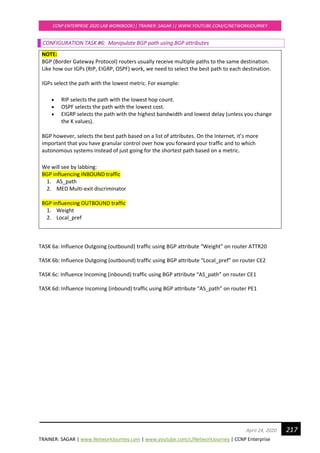
CONFIGURATION TASK #2: Configure OSPF (single-area)
MUMBAIR1(config)# #global OSPF configuration
router ospf 1
router-id 1.1.1.1
network 192.168.23.0 0.0.0.255 area 0
MUMBAIR2(config)# #global OSPF configuration
router ospf 1
router-id 2.2.2.2
network 192.168.23.0 0.0.0.255 area 0
MUMBAIR3(config)# #global OSPF configuration
router ospf 1
router-id 3.3.3.3
network 192.168.23.0 0.0.0.255 area 0
MUMBAIR7(config)# #global OSPF configuration
router ospf 1
router-id 7.7.7.7
network 192.168.23.0 0.0.0.255 area 0
MUMBAIR4(config)# #global OSPF configuration
router ospf 1
router-id 4.4.4.4
network 192.168.23.0 0.0.0.255 area 0
By default, any router can become DR, BDR, DROTHERS as per the configurations are done.
To make the rightful Router as DR and BDR based out of known formulae, DR = Priority+R-ID
Make use of CLI command “clear ip ospf process” → Reloads the ospf process so that re-election
happens.
MUMBAIR1#, MUMBAIR2#, MUMBAIR3#, MUMBAIR4#, MUMBAIR7#
clear ip ospf process
Reset ALL OSPF processes? [no]: yes](https://image.slidesharecdn.com/ccnpenterpriseworkbookv1-201010132734/85/Ccnp-enterprise-workbook-v1-0-completed-till-weigth-146-320.jpg)
![TRAINER: SAGAR | www.NetworkJourney.com | www.youtube.com/c/NetworkJourney | CCNP Enterprise
CCNP ENTERPRISE 2020 LAB WORKBOOK|| TRAINER: SAGAR || WWW.YOUTUBE.COM/C/NETWORKJOURNEY
147April 24, 2020
You can also enable the “debug” commands to see the packet captures:
----
#
DEBUG OSPF
----
MUMBAIR1#debug ip ospf packet
OSPF packet debugging is on
MUMBAIR1#debug ip ospf adj
OSPF adjacency debugging is on
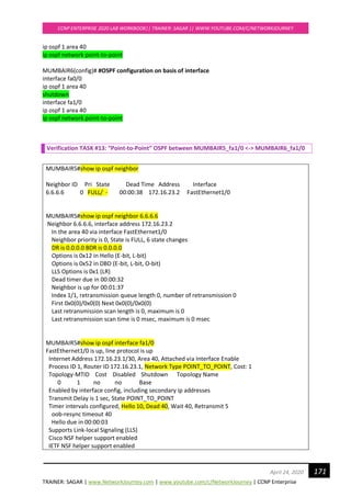
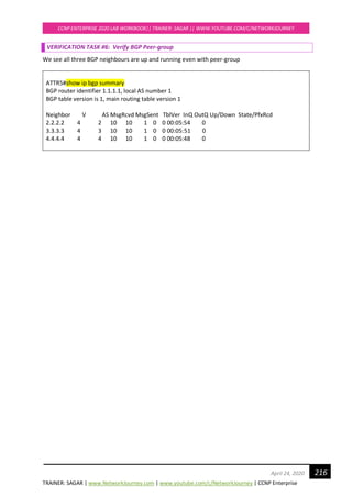
VERIFICATION TASKS#2
MUMBAIR1#show ip ospf neighbor
Neighbor ID Pri State Dead Time Address Interface
2.2.2.2 1 FULL/DROTHER 00:00:30 192.168.23.13 Ethernet0/0
3.3.3.3 1 FULL/DR 00:00:32 192.168.23.12 Ethernet0/0
MUMBAIR1#
MUMBAIR1#show ip ospf database
OSPF Router with ID (1.1.1.1) (Process ID 100)
Router Link States (Area 0)
Link ID ADV Router Age Seq# Checksum Link count
1.1.1.1 1.1.1.1 1474 0x80000005 0x0035BB 2
2.2.2.2 2.2.2.2 365 0x8000000B 0x0033A9 2
3.3.3.3 3.3.3.3 1475 0x80000006 0x00F8DD 2
Net Link States (Area 0)
Link ID ADV Router Age Seq# Checksum
192.168.23.12 3.3.3.3 365 0x80000007 0x003649
MUMBAIR1#
MUMBAIR1#show ip route
<!-output omitted-!>
Gateway of last resort is not set
1.0.0.0/8 is variably subnetted, 2 subnets, 2 masks
C 1.1.1.0/24 is directly connected, Loopback1
L 1.1.1.1/32 is directly connected, Loopback1
2.0.0.0/32 is subnetted, 1 subnets
O 2.2.2.2 [110/11] via 192.168.23.13, 00:05:59, Ethernet0/0
3.0.0.0/32 is subnetted, 1 subnets
O 3.3.3.3 [110/11] via 192.168.23.12, 00:24:39, Ethernet0/0
192.168.23.0/24 is variably subnetted, 2 subnets, 2 masks](https://image.slidesharecdn.com/ccnpenterpriseworkbookv1-201010132734/85/Ccnp-enterprise-workbook-v1-0-completed-till-weigth-147-320.jpg)
![TRAINER: SAGAR | www.NetworkJourney.com | www.youtube.com/c/NetworkJourney | CCNP Enterprise
CCNP ENTERPRISE 2020 LAB WORKBOOK|| TRAINER: SAGAR || WWW.YOUTUBE.COM/C/NETWORKJOURNEY
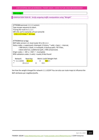
149April 24, 2020
VERIFICATION TASK #3:
MUMBAIR2#show ip ospf neighbor
3.3.3.3 0 FULL/DROTHER 00:00:36 192.168.23.12 Ethernet0/0
3.3.3.3 is now acting as DROTHER with OSPF Priority = 0
MUMBAIR3#show ip ospf interface e0/0
Ethernet0/0 is up, line protocol is up
Internet Address 192.168.23.12/24, Area 0, Attached via Network Statement
Process ID 100, Router ID 3.3.3.3, Network Type BROADCAST, Cost: 10
Topology-MTID Cost Disabled Shutdown Topology Name
0 10 no no Base
Transmit Delay is 1 sec, State DROTHER, Priority 0
Designated Router (ID) 2.2.2.2, Interface address 192.168.23.13
Backup Designated router (ID) 1.1.1.1, Interface address 192.168.23.11
Old designated Router (ID) 3.3.3.3, Interface address 192.168.23.12
CONFIGURATION TASK #4: MANIPULATE ROUTER-ID ELECTION
MUMBAIR1#(config)
router ospf 1
router-id 11.11.11.11
MUMBAIR2#(config)
router ospf 1
router-id 22.22.22.22
MUMBAIR3#(config)
router ospf 1
router-id 33.33.33.33
clear ip ospf process *
[yes]
This will re-elect the DR and BDR on updated Router-ID.
CONFIGURATION TASK #5: MANIPULATE HELLO/HOLD TIMER
MUMBAIR1#(config)
interface e0/0
ip ospf hello-timer 5
NOTE:
Hello Packet contains below parameters which are used for initial negotiation and must be
identical on both the sides:
1. Network ID
2. Area ID](https://image.slidesharecdn.com/ccnpenterpriseworkbookv1-201010132734/85/Ccnp-enterprise-workbook-v1-0-completed-till-weigth-149-320.jpg)
![TRAINER: SAGAR | www.NetworkJourney.com | www.youtube.com/c/NetworkJourney | CCNP Enterprise
CCNP ENTERPRISE 2020 LAB WORKBOOK|| TRAINER: SAGAR || WWW.YOUTUBE.COM/C/NETWORKJOURNEY
159April 24, 2020
interfaces whose addresses fall within the address range specified for the network area
command.
If you later disable the ip ospf area command, the interface still will run OSPFv2 as long as its
network address matches the range of addresses that is specified by the network area command.
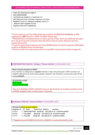
VERIFICATION TASK #12: OSPF (Multi-area) between AREA 0, Area 40 and Area 80
MUMBAIR1#show ip ospf neighbor
Neighbor ID Pri State Dead Time Address Interface
2.2.2.2 1 2WAY/DROTHER 00:00:37 192.168.23.13 FastEthernet0/0
3.3.3.3 1 2WAY/DROTHER 00:00:37 192.168.23.12 FastEthernet0/0
4.4.4.4 1 FULL/BDR 00:00:31 192.168.23.14 FastEthernet0/0
7.7.7.7 1 FULL/DR 00:00:33 192.168.23.15 FastEthernet0/0
MUMBAIR1#show ip ospf database
OSPF Router with ID (1.1.1.1) (Process ID 1)
Router Link States (Area 0)
Link ID ADV Router Age Seq# Checksum Link count
1.1.1.1 1.1.1.1 25 0x80000002 0x008589 1
2.2.2.2 2.2.2.2 26 0x80000002 0x0058AB 1
3.3.3.3 3.3.3.3 26 0x80000002 0x00FA03 1
4.4.4.4 4.4.4.4 16 0x80000002 0x00CD25 1
7.7.7.7 7.7.7.7 26 0x80000002 0x00F3E6 1
Net Link States (Area 0)
Link ID ADV Router Age Seq# Checksum
192.168.23.15 7.7.7.7 16 0x80000002 0x00C27A
Summary Net Link States (Area 0)
Link ID ADV Router Age Seq# Checksum
10.100.100.0 4.4.4.4 47 0x80000001 0x0093C5
33.33.33.0 2.2.2.2 66 0x80000001 0x00AE22
34.34.34.1 2.2.2.2 24 0x80000001 0x008A41
172.16.23.0 4.4.4.4 8 0x80000001 0x008FCA
MUMBAIR1#show ip route ospf | beg Gateway
Gateway of last resort is not set
10.0.0.0/24 is subnetted, 1 subnets
O IA 10.100.100.0 [110/2] via 192.168.23.14, 00:00:41, FastEthernet0/0
33.0.0.0/24 is subnetted, 1 subnets
O IA 33.33.33.0 [110/2] via 192.168.23.13, 00:00:41, FastEthernet0/0
34.0.0.0/32 is subnetted, 1 subnets
O IA 34.34.34.1 [110/3] via 192.168.23.13, 00:00:41, FastEthernet0/0
172.16.0.0/30 is subnetted, 1 subnets
O IA 172.16.23.0 [110/3] via 192.168.23.14, 00:00:37, FastEthernet0/0](https://image.slidesharecdn.com/ccnpenterpriseworkbookv1-201010132734/85/Ccnp-enterprise-workbook-v1-0-completed-till-weigth-159-320.jpg)
![TRAINER: SAGAR | www.NetworkJourney.com | www.youtube.com/c/NetworkJourney | CCNP Enterprise
CCNP ENTERPRISE 2020 LAB WORKBOOK|| TRAINER: SAGAR || WWW.YOUTUBE.COM/C/NETWORKJOURNEY
160April 24, 2020
** We can see LSA1, LSA2 and LSA3
MUMBAIR3#show ip ospf neighbor
Neighbor ID Pri State Dead Time Address Interface
1.1.1.1 1 2WAY/DROTHER 00:00:35 192.168.23.11 FastEthernet0/0
2.2.2.2 1 2WAY/DROTHER 00:00:33 192.168.23.13 FastEthernet0/0
4.4.4.4 1 FULL/BDR 00:00:38 192.168.23.14 FastEthernet0/0
7.7.7.7 1 FULL/DR 00:00:35 192.168.23.15 FastEthernet0/0
MUMBAIR3#show ip ospf database
OSPF Router with ID (3.3.3.3) (Process ID 1)
Router Link States (Area 0)
Link ID ADV Router Age Seq# Checksum Link count
1.1.1.1 1.1.1.1 166 0x80000002 0x008589 1
2.2.2.2 2.2.2.2 166 0x80000002 0x0058AB 1
3.3.3.3 3.3.3.3 164 0x80000002 0x00FA03 1
4.4.4.4 4.4.4.4 151 0x80000002 0x00CD25 1
7.7.7.7 7.7.7.7 165 0x80000002 0x00F3E6 1
Net Link States (Area 0)
Link ID ADV Router Age Seq# Checksum
192.168.23.15 7.7.7.7 151 0x80000002 0x00C27A
Summary Net Link States (Area 0)
Link ID ADV Router Age Seq# Checksum
10.100.100.0 4.4.4.4 181 0x80000001 0x0093C5
33.33.33.0 2.2.2.2 213 0x80000001 0x00AE22
34.34.34.1 2.2.2.2 115 0x80000001 0x008A41
172.16.23.0 4.4.4.4 105 0x80000001 0x008FCA
MUMBAIR3#show ip route ospf | beg Gateway
Gateway of last resort is not set
10.0.0.0/24 is subnetted, 1 subnets
O IA 10.100.100.0 [110/2] via 192.168.23.14, 00:40:50, FastEthernet0/0
33.0.0.0/24 is subnetted, 1 subnets
O IA 33.33.33.0 [110/2] via 192.168.23.13, 00:41:15, FastEthernet0/0
34.0.0.0/32 is subnetted, 1 subnets
O IA 34.34.34.1 [110/3] via 192.168.23.13, 00:29:40, FastEthernet0/0
172.16.0.0/30 is subnetted, 1 subnets
O IA 172.16.23.0 [110/3] via 192.168.23.14, 00:40:50, FastEthernet0/0
** We can see LSA1, LSA2 and LSA3
MUMBAIR7#show ip ospf neighbor
Neighbor ID Pri State Dead Time Address Interface](https://image.slidesharecdn.com/ccnpenterpriseworkbookv1-201010132734/85/Ccnp-enterprise-workbook-v1-0-completed-till-weigth-160-320.jpg)
![TRAINER: SAGAR | www.NetworkJourney.com | www.youtube.com/c/NetworkJourney | CCNP Enterprise
CCNP ENTERPRISE 2020 LAB WORKBOOK|| TRAINER: SAGAR || WWW.YOUTUBE.COM/C/NETWORKJOURNEY
161April 24, 2020
1.1.1.1 1 FULL/DROTHER 00:00:30 192.168.23.11 FastEthernet0/0
2.2.2.2 1 FULL/DROTHER 00:00:31 192.168.23.13 FastEthernet0/0
3.3.3.3 1 FULL/DROTHER 00:00:32 192.168.23.12 FastEthernet0/0
4.4.4.4 1 FULL/BDR 00:00:36 192.168.23.14 FastEthernet0/0
MUMBAIR7#show ip ospf database
OSPF Router with ID (7.7.7.7) (Process ID 1)
Router Link States (Area 0)
Link ID ADV Router Age Seq# Checksum Link count
1.1.1.1 1.1.1.1 436 0x80000002 0x008589 1
2.2.2.2 2.2.2.2 436 0x80000002 0x0058AB 1
3.3.3.3 3.3.3.3 436 0x80000002 0x00FA03 1
4.4.4.4 4.4.4.4 421 0x80000002 0x00CD25 1
7.7.7.7 7.7.7.7 435 0x80000002 0x00F3E6 1
Net Link States (Area 0)
Link ID ADV Router Age Seq# Checksum
192.168.23.15 7.7.7.7 421 0x80000002 0x00C27A
Summary Net Link States (Area 0)
Link ID ADV Router Age Seq# Checksum
10.100.100.0 4.4.4.4 452 0x80000001 0x0093C5
33.33.33.0 2.2.2.2 482 0x80000001 0x00AE22
34.34.34.1 2.2.2.2 384 0x80000001 0x008A41
172.16.23.0 4.4.4.4 376 0x80000001 0x008FCA
MUMBAIR7#show ip route ospf | beg Gateway
Gateway of last resort is not set
10.0.0.0/24 is subnetted, 1 subnets
O IA 10.100.100.0 [110/2] via 192.168.23.14, 00:07:00, FastEthernet0/0
33.0.0.0/24 is subnetted, 1 subnets
O IA 33.33.33.0 [110/2] via 192.168.23.13, 00:07:15, FastEthernet0/0
34.0.0.0/32 is subnetted, 1 subnets
O IA 34.34.34.1 [110/3] via 192.168.23.13, 00:06:28, FastEthernet0/0
172.16.0.0/30 is subnetted, 1 subnets
O IA 172.16.23.0 [110/3] via 192.168.23.14, 00:06:20, FastEthernet0/0
** We can see LSA1, LSA2 and LSA3
MUMBAIR2#show ip ospf neighbor
Neighbor ID Pri State Dead Time Address Interface
1.1.1.1 1 2WAY/DROTHER 00:00:33 192.168.23.11 FastEthernet0/0
3.3.3.3 1 2WAY/DROTHER 00:00:31 192.168.23.12 FastEthernet0/0
4.4.4.4 1 FULL/BDR 00:00:36 192.168.23.14 FastEthernet0/0
7.7.7.7 1 FULL/DR 00:00:38 192.168.23.15 FastEthernet0/0
33.33.33.33 1 FULL/DR 00:00:37 33.33.33.2 FastEthernet1/0](https://image.slidesharecdn.com/ccnpenterpriseworkbookv1-201010132734/85/Ccnp-enterprise-workbook-v1-0-completed-till-weigth-161-320.jpg)
![TRAINER: SAGAR | www.NetworkJourney.com | www.youtube.com/c/NetworkJourney | CCNP Enterprise
CCNP ENTERPRISE 2020 LAB WORKBOOK|| TRAINER: SAGAR || WWW.YOUTUBE.COM/C/NETWORKJOURNEY
162April 24, 2020
MUMBAIR2#show ip ospf database
OSPF Router with ID (2.2.2.2) (Process ID 1)
Router Link States (Area 0)
Link ID ADV Router Age Seq# Checksum Link count
1.1.1.1 1.1.1.1 761 0x80000002 0x008589 1
2.2.2.2 2.2.2.2 14 0x80000003 0x0056AC 1
3.3.3.3 3.3.3.3 761 0x80000002 0x00FA03 1
4.4.4.4 4.4.4.4 746 0x80000002 0x00CD25 1
7.7.7.7 7.7.7.7 760 0x80000002 0x00F3E6 1
Net Link States (Area 0)
Link ID ADV Router Age Seq# Checksum
192.168.23.15 7.7.7.7 746 0x80000002 0x00C27A
Summary Net Link States (Area 0)
Link ID ADV Router Age Seq# Checksum
10.100.100.0 4.4.4.4 777 0x80000001 0x0093C5
33.33.33.0 2.2.2.2 10 0x80000001 0x00AE22
34.34.34.1 2.2.2.2 10 0x80000001 0x008A41
172.16.23.0 4.4.4.4 701 0x80000001 0x008FCA
Router Link States (Area 80)
Link ID ADV Router Age Seq# Checksum Link count
2.2.2.2 2.2.2.2 14 0x80000003 0x00381E 1
33.33.33.33 33.33.33.33 20 0x80000003 0x00469E 2
Net Link States (Area 80)
Link ID ADV Router Age Seq# Checksum
33.33.33.2 33.33.33.33 20 0x80000001 0x00CBF7
Summary Net Link States (Area 80)
Link ID ADV Router Age Seq# Checksum
10.100.100.0 2.2.2.2 10 0x80000001 0x00D986
172.16.23.0 2.2.2.2 10 0x80000001 0x00D58B
192.168.23.0 2.2.2.2 10 0x80000001 0x00A70C
MUMBAIR2#show ip route | beg Gateway
Gateway of last resort is not set
10.0.0.0/24 is subnetted, 1 subnets
O IA 10.100.100.0 [110/2] via 192.168.23.14, 00:00:18, FastEthernet0/0
33.0.0.0/8 is variably subnetted, 2 subnets, 2 masks
C 33.33.33.0/24 is directly connected, FastEthernet1/0
L 33.33.33.1/32 is directly connected, FastEthernet1/0
34.0.0.0/32 is subnetted, 1 subnets
O 34.34.34.1 [110/2] via 33.33.33.2, 00:00:18, FastEthernet1/0](https://image.slidesharecdn.com/ccnpenterpriseworkbookv1-201010132734/85/Ccnp-enterprise-workbook-v1-0-completed-till-weigth-162-320.jpg)
![TRAINER: SAGAR | www.NetworkJourney.com | www.youtube.com/c/NetworkJourney | CCNP Enterprise
CCNP ENTERPRISE 2020 LAB WORKBOOK|| TRAINER: SAGAR || WWW.YOUTUBE.COM/C/NETWORKJOURNEY
163April 24, 2020
172.16.0.0/30 is subnetted, 1 subnets
O IA 172.16.23.0 [110/3] via 192.168.23.14, 00:00:18, FastEthernet0/0
192.168.23.0/24 is variably subnetted, 2 subnets, 2 masks
C 192.168.23.0/24 is directly connected, FastEthernet0/0
L 192.168.23.13/32 is directly connected, FastEthernet0/0
**MUMBAIR2 is ABR router between Area 0 and Area 80
**We can see LSA1, LSA2 and LSA3
**MUMBAIR2 has 2 DR in OSPF Neighbor table.
First DR state between MUMBAIR2_Fa0/0 AREA 0 <-> MUMBAIR7 AREA 0
Second DR state between MUMBAIR2_Fa1/0 AREA 80 <-> ROMER1 AREA 80
MUMBAIR4#show ip ospf neighbor
Neighbor ID Pri State Dead Time Address Interface
1.1.1.1 1 FULL/DROTHER 00:00:34 192.168.23.11 FastEthernet0/0
2.2.2.2 1 FULL/DROTHER 00:00:39 192.168.23.13 FastEthernet0/0
3.3.3.3 1 FULL/DROTHER 00:00:31 192.168.23.12 FastEthernet0/0
7.7.7.7 1 FULL/DR 00:00:35 192.168.23.15 FastEthernet0/0
5.5.5.5 1 2WAY/DROTHER 00:00:35 10.100.100.2 FastEthernet1/0
6.6.6.6 1 FULL/BDR 00:00:36 10.100.100.3 FastEthernet1/0
13.13.13.13 1 FULL/DR 00:00:38 10.100.100.4 FastEthernet1/0
MUMBAIR4#show ip ospf database
OSPF Router with ID (4.4.4.4) (Process ID 1)
Router Link States (Area 0)
Link ID ADV Router Age Seq# Checksum Link count
1.1.1.1 1.1.1.1 1624 0x80000002 0x008589 1
2.2.2.2 2.2.2.2 879 0x80000003 0x0056AC 1
3.3.3.3 3.3.3.3 1624 0x80000002 0x00FA03 1
4.4.4.4 4.4.4.4 1609 0x80000002 0x00CD25 1
7.7.7.7 7.7.7.7 1624 0x80000002 0x00F3E6 1
Net Link States (Area 0)
Link ID ADV Router Age Seq# Checksum
192.168.23.15 7.7.7.7 1610 0x80000002 0x00C27A
Summary Net Link States (Area 0)
Link ID ADV Router Age Seq# Checksum
10.100.100.0 4.4.4.4 1639 0x80000001 0x0093C5
33.33.33.0 2.2.2.2 874 0x80000001 0x00AE22
34.34.34.1 2.2.2.2 874 0x80000001 0x008A41
172.16.23.0 4.4.4.4 1563 0x80000001 0x008FCA
Router Link States (Area 40)
Link ID ADV Router Age Seq# Checksum Link count](https://image.slidesharecdn.com/ccnpenterpriseworkbookv1-201010132734/85/Ccnp-enterprise-workbook-v1-0-completed-till-weigth-163-320.jpg)
![TRAINER: SAGAR | www.NetworkJourney.com | www.youtube.com/c/NetworkJourney | CCNP Enterprise
CCNP ENTERPRISE 2020 LAB WORKBOOK|| TRAINER: SAGAR || WWW.YOUTUBE.COM/C/NETWORKJOURNEY
164April 24, 2020
4.4.4.4 4.4.4.4 1577 0x80000002 0x001F47 1
5.5.5.5 5.5.5.5 1578 0x80000003 0x00DDC4 2
6.6.6.6 6.6.6.6 1578 0x80000003 0x00B9DE 2
13.13.13.13 13.13.13.13 1579 0x80000002 0x009784 1
Net Link States (Area 40)
Link ID ADV Router Age Seq# Checksum
10.100.100.4 13.13.13.13 1579 0x80000001 0x003680
172.16.23.2 6.6.6.6 1591 0x80000001 0x00091A
Summary Net Link States (Area 40)
Link ID ADV Router Age Seq# Checksum
33.33.33.0 4.4.4.4 873 0x80000003 0x00784D
34.34.34.1 4.4.4.4 864 0x80000005 0x00506E
192.168.23.0 4.4.4.4 1639 0x80000001 0x006B40
MUMBAIR4#show ip route ospf | beg Gateway
Gateway of last resort is not set
33.0.0.0/24 is subnetted, 1 subnets
O IA 33.33.33.0 [110/2] via 192.168.23.13, 00:14:42, FastEthernet0/0
34.0.0.0/32 is subnetted, 1 subnets
O IA 34.34.34.1 [110/3] via 192.168.23.13, 00:14:42, FastEthernet0/0
172.16.0.0/30 is subnetted, 1 subnets
O 172.16.23.0 [110/2] via 10.100.100.3, 00:26:12, FastEthernet1/0
[110/2] via 10.100.100.2, 00:26:12, FastEthernet1/0
**MUMBAIR4 is ABR router between Area 0 and Area 40
** We can see LSA1, LSA2 and LSA3
**MUMBAIR4 has 2 DR in OSPF Neighbor table.
First DR state between MUMBAIR4_Fa0/0 AREA 0 <-> MUMBAIR7 AREA 0
Second DR state between MUMBAIR4_Fa1/0 AREA 40 <-> MUMBAIRR13 AREA 40
MUMBAIR5#show ip ospf neighbor
Neighbor ID Pri State Dead Time Address Interface
6.6.6.6 1 FULL/DR 00:00:39 172.16.23.2 FastEthernet1/0
4.4.4.4 1 2WAY/DROTHER 00:00:32 10.100.100.1 FastEthernet0/0
6.6.6.6 1 FULL/BDR 00:00:34 10.100.100.3 FastEthernet0/0
13.13.13.13 1 FULL/DR 00:00:38 10.100.100.4 FastEthernet0/0
MUMBAIR5#show ip ospf database
OSPF Router with ID (5.5.5.5) (Process ID 1)
Router Link States (Area 40)
Link ID ADV Router Age Seq# Checksum Link count
4.4.4.4 4.4.4.4 1875 0x80000002 0x001F47 1
5.5.5.5 5.5.5.5 1874 0x80000003 0x00DDC4 2
6.6.6.6 6.6.6.6 1875 0x80000003 0x00B9DE 2
13.13.13.13 13.13.13.13 1875 0x80000002 0x009784 1](https://image.slidesharecdn.com/ccnpenterpriseworkbookv1-201010132734/85/Ccnp-enterprise-workbook-v1-0-completed-till-weigth-164-320.jpg)
![TRAINER: SAGAR | www.NetworkJourney.com | www.youtube.com/c/NetworkJourney | CCNP Enterprise
CCNP ENTERPRISE 2020 LAB WORKBOOK|| TRAINER: SAGAR || WWW.YOUTUBE.COM/C/NETWORKJOURNEY
165April 24, 2020
Net Link States (Area 40)
Link ID ADV Router Age Seq# Checksum
10.100.100.4 13.13.13.13 1875 0x80000001 0x003680
172.16.23.2 6.6.6.6 1885 0x80000001 0x00091A
Summary Net Link States (Area 40)
Link ID ADV Router Age Seq# Checksum
33.33.33.0 4.4.4.4 1172 0x80000003 0x00784D
34.34.34.1 4.4.4.4 1162 0x80000005 0x00506E
192.168.23.0 4.4.4.4 1937 0x80000001 0x006B40
MUMBAIR5#show ip route | beg Gateway
Gateway of last resort is not set
10.0.0.0/8 is variably subnetted, 2 subnets, 2 masks
C 10.100.100.0/24 is directly connected, FastEthernet0/0
L 10.100.100.2/32 is directly connected, FastEthernet0/0
33.0.0.0/24 is subnetted, 1 subnets
O IA 33.33.33.0 [110/3] via 10.100.100.1, 00:19:37, FastEthernet0/0
34.0.0.0/32 is subnetted, 1 subnets
O IA 34.34.34.1 [110/4] via 10.100.100.1, 00:19:32, FastEthernet0/0
172.16.0.0/16 is variably subnetted, 2 subnets, 2 masks
C 172.16.23.0/30 is directly connected, FastEthernet1/0
L 172.16.23.1/32 is directly connected, FastEthernet1/0
O IA 192.168.23.0/24 [110/2] via 10.100.100.1, 00:31:07, FastEthernet0/0
**We can see LSA1, LSA2 and LSA3
**Something you need to be aware of is that the DR/BDR election is per multi-access
segment…not per area!).
**Most CCNA students think that this DR/BDR election is done per area but this is incorrect.
**Hence, we see 2 DR’s in AREA 40
MUMBAIR13 (RID = 13.13.13.13) is DR for Multiaccess Broadcast segment and,
MUMBAIR6 (RID=6.6.6.6) is DR for the segment network 172.16.23.0/24 between MUMBAIR6 <->
MUMBAIR5
MUMBAIR6#show ip ospf neighbor
Neighbor ID Pri State Dead Time Address Interface
5.5.5.5 1 FULL/BDR 00:00:35 172.16.23.1 FastEthernet1/0
4.4.4.4 1 FULL/DROTHER 00:00:38 10.100.100.1 FastEthernet0/0
5.5.5.5 1 FULL/DROTHER 00:00:30 10.100.100.2 FastEthernet0/0
13.13.13.13 1 FULL/DR 00:00:34 10.100.100.4 FastEthernet0/0
MUMBAIR6#show ip ospf database
OSPF Router with ID (6.6.6.6) (Process ID 1)
Router Link States (Area 40)](https://image.slidesharecdn.com/ccnpenterpriseworkbookv1-201010132734/85/Ccnp-enterprise-workbook-v1-0-completed-till-weigth-165-320.jpg)
![TRAINER: SAGAR | www.NetworkJourney.com | www.youtube.com/c/NetworkJourney | CCNP Enterprise
CCNP ENTERPRISE 2020 LAB WORKBOOK|| TRAINER: SAGAR || WWW.YOUTUBE.COM/C/NETWORKJOURNEY
166April 24, 2020
Link ID ADV Router Age Seq# Checksum Link count
4.4.4.4 4.4.4.4 1236 0x80000003 0x001D48 1
5.5.5.5 5.5.5.5 1250 0x80000004 0x00DBC5 2
6.6.6.6 6.6.6.6 1265 0x80000004 0x00B7DF 2
13.13.13.13 13.13.13.13 1198 0x80000003 0x009585 1
Net Link States (Area 40)
Link ID ADV Router Age Seq# Checksum
10.100.100.4 13.13.13.13 1198 0x80000002 0x003481
172.16.23.2 6.6.6.6 1265 0x80000002 0x00071B
Summary Net Link States (Area 40)
Link ID ADV Router Age Seq# Checksum
33.33.33.0 4.4.4.4 478 0x80000004 0x00764E
34.34.34.1 4.4.4.4 478 0x80000006 0x004E6F
192.168.23.0 4.4.4.4 1236 0x80000002 0x006941
MUMBAIR6#show ip route ospf | beg Gateway
Gateway of last resort is not set
33.0.0.0/24 is subnetted, 1 subnets
O IA 33.33.33.0 [110/3] via 10.100.100.1, 00:41:39, FastEthernet0/0
34.0.0.0/32 is subnetted, 1 subnets
O IA 34.34.34.1 [110/4] via 10.100.100.1, 00:41:30, FastEthernet0/0
O IA 192.168.23.0/24 [110/2] via 10.100.100.1, 00:53:09, FastEthernet0/0
** We can see LSA1, LSA2 and LSA3
**MUMBAIR6 see MUMBAIR5 as BDR for two times in the OSPF NEIGHBOR table
**First MUMBAIR6 -> MUMBAIR5 over MULTIACCESS Broadcast network
**Secondly MUMBAIR6 -> MUMBAIR5 over 172.16.23.0/24 segment
ROMER1#show ip ospf neighbor
Neighbor ID Pri State Dead Time Address Interface
2.2.2.2 1 FULL/BDR 00:00:36 33.33.33.1 FastEthernet1/0
ROMER1#show ip ospf database
OSPF Router with ID (33.33.33.33) (Process ID 1)
Router Link States (Area 80)
Link ID ADV Router Age Seq# Checksum Link count
2.2.2.2 2.2.2.2 1060 0x80000004 0x00361F 1
33.33.33.33 33.33.33.33 1277 0x80000004 0x00449F 2](https://image.slidesharecdn.com/ccnpenterpriseworkbookv1-201010132734/85/Ccnp-enterprise-workbook-v1-0-completed-till-weigth-166-320.jpg)
![TRAINER: SAGAR | www.NetworkJourney.com | www.youtube.com/c/NetworkJourney | CCNP Enterprise
CCNP ENTERPRISE 2020 LAB WORKBOOK|| TRAINER: SAGAR || WWW.YOUTUBE.COM/C/NETWORKJOURNEY
167April 24, 2020
Net Link States (Area 80)
Link ID ADV Router Age Seq# Checksum
33.33.33.2 33.33.33.33 1277 0x80000002 0x00C9F8
Summary Net Link States (Area 80)
Link ID ADV Router Age Seq# Checksum
10.100.100.0 2.2.2.2 1060 0x80000002 0x00D787
172.16.23.0 2.2.2.2 1060 0x80000002 0x00D38C
192.168.23.0 2.2.2.2 1060 0x80000002 0x00A50D
ROMER1#show ip route ospf | beg Gateway
Gateway of last resort is not set
10.0.0.0/24 is subnetted, 1 subnets
O IA 10.100.100.0 [110/3] via 33.33.33.1, 00:52:03, FastEthernet1/0
172.16.0.0/30 is subnetted, 1 subnets
O IA 172.16.23.0 [110/4] via 33.33.33.1, 00:52:03, FastEthernet1/0
O IA 192.168.23.0/24 [110/2] via 33.33.33.1, 00:52:03, FastEthernet1/0
** Rome is Area 80, however, directly connected to Area 0’s ABR (MUMBAIR2)
** We can see LSA1, LSA2 and LSA3
VATICANR1#sh ip osp nei
Neighbor ID Pri State Dead Time Address Interface
13.13.13.13 1 FULL/BDR 00:00:36 47.47.47.1 FastEthernet0/0
VATICANR1#show ip osp database
OSPF Router with ID (49.49.49.1) (Process ID 1)
Router Link States (Area 100)
Link ID ADV Router Age Seq# Checksum Link count
13.13.13.13 13.13.13.13 513 0x80000002 0x003B70 1
49.49.49.1 49.49.49.1 516 0x80000003 0x002D16 2
Net Link States (Area 100)
Link ID ADV Router Age Seq# Checksum
47.47.47.2 49.49.49.1 516 0x80000001 0x0079D3
** We can only LSA1 and LS2
** No OSPF LSA type 3 found because Area 100 is not connected to any of Area 0’s ABR router.
** It is always the Area 0’s ABR which generate LSA type 3.
** Hence, we need to construct virtual-link between Area 100 and Area 0 to generate LSA 3.
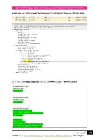
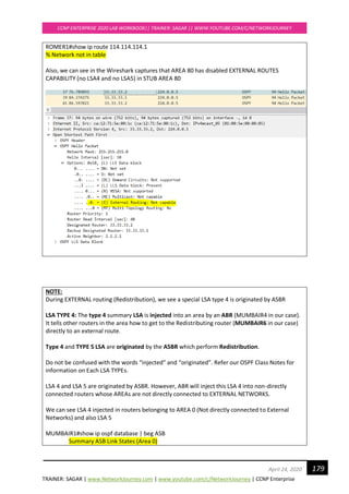
** We will see this lab (virtual links) in the later part of this workbook](https://image.slidesharecdn.com/ccnpenterpriseworkbookv1-201010132734/85/Ccnp-enterprise-workbook-v1-0-completed-till-weigth-167-320.jpg)
![TRAINER: SAGAR | www.NetworkJourney.com | www.youtube.com/c/NetworkJourney | CCNP Enterprise
CCNP ENTERPRISE 2020 LAB WORKBOOK|| TRAINER: SAGAR || WWW.YOUTUBE.COM/C/NETWORKJOURNEY
175April 24, 2020
Net Link States (Area 80)
Link ID ADV Router Age Seq# Checksum
33.33.33.2 34.34.34.1 394 0x80000004 0x006399
Summary Net Link States (Area 80)
Link ID ADV Router Age Seq# Checksum
0.0.0.0 2.2.2.2 376 0x80000002 0x0073C1
10.100.100.0 2.2.2.2 1898 0x80000005 0x00EF6E
192.168.23.0 2.2.2.2 1898 0x80000005 0x00BDF3
ROMER1#show ip route ospf
Gateway of last resort is 33.33.33.1 to network 0.0.0.0
O*IA 0.0.0.0/0 [110/2] via 33.33.33.1, 00:36:51, FastEthernet1/0
10.0.0.0/24 is subnetted, 1 subnets
O IA 10.100.100.0 [110/3] via 33.33.33.1, 00:36:51, FastEthernet1/0
O IA 192.168.23.0/24 [110/2] via 33.33.33.1, 00:36:51, FastEthernet1/0
**default route (0.0.0.0/0) is added in ROUTING TABLE of OSPF AREA 80 pointing towards ABR in
order to reach external routes.
**LSA type 5 are suppressed in OSPF DATABASE TABLE of OSPF AREA 80
**Yet can reach external routes as inserted 0.0.0.0 in OSPF DATABASE TABLE pointing towards
ABR
NOTE:
A stub area is an area in which you do not allow advertisements of external routes, which thus
reduces the size of the database even more. Instead, a default summary route (0.0.0.0) is inserted
into the stub area in order to reach these external routes. If you have no external routes in your
network, then you have no need to define stub areas.
Stub areas are shielded from external routes but receive information about networks that belong
to other areas of the same OSPF domain.](https://image.slidesharecdn.com/ccnpenterpriseworkbookv1-201010132734/85/Ccnp-enterprise-workbook-v1-0-completed-till-weigth-175-320.jpg)
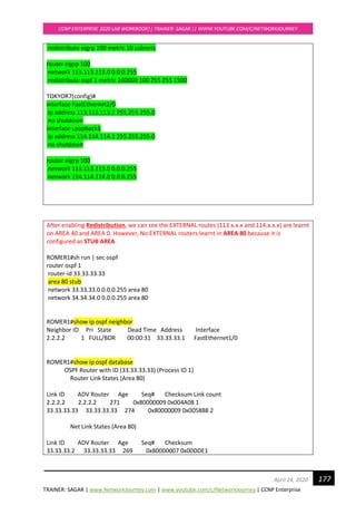
![TRAINER: SAGAR | www.NetworkJourney.com | www.youtube.com/c/NetworkJourney | CCNP Enterprise
CCNP ENTERPRISE 2020 LAB WORKBOOK|| TRAINER: SAGAR || WWW.YOUTUBE.COM/C/NETWORKJOURNEY
178April 24, 2020
Summary Net Link States (Area 80)
Link ID ADV Router Age Seq# Checksum
0.0.0.0 2.2.2.2 276 0x80000001 0x0075C0
10.100.100.0 2.2.2.2 276 0x80000006 0x00ED6F
172.16.23.0 2.2.2.2 276 0x80000002 0x00F170
192.168.23.0 2.2.2.2 276 0x80000006 0x00BBF4
**STUB AREA does not support LSA 5 type (NO EXTERNAL ROUTE CAPABILTY in STUB AREA)
ROMER1#show ip route ospf | beg Gateway
Gateway of last resort is 33.33.33.1 to network 0.0.0.0
O*IA 0.0.0.0/0 [110/2] via 33.33.33.1, 00:04:29, FastEthernet1/0
10.0.0.0/24 is subnetted, 1 subnets
O IA 10.100.100.0 [110/3] via 33.33.33.1, 00:04:29, FastEthernet1/0
172.16.0.0/30 is subnetted, 1 subnets
O IA 172.16.23.0 [110/4] via 33.33.33.1, 00:04:29, FastEthernet1/0
O IA 192.168.23.0/24 [110/2] via 33.33.33.1, 00:04:29, FastEthernet1/0
NOTE:
A stub area is an area in which you do not allow advertisements of external routes, which thus
reduces the size of the database even more. Instead, a default summary route (0.0.0.0) is inserted
into the stub area in order to reach these external routes.
STUB AREA suppresses all LSA Type 5 and LSA Type 4 and inject Default Router (0.0.0.0/0)
pointing towards ABR (2.2.2.2 in our Example) so that we still have reachability to EXTERNAL
ROUTES (113.x.x.x and 114.x.x.x in our case)
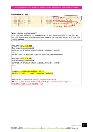
Let us initiate PING and TRACEROUTE:
ROMER1#ping 114.114.114.1
Type escape sequence to abort.
Sending 5, 100-byte ICMP Echos to 114.114.114.1, timeout is 2 seconds:
!!!!!
Success rate is 100 percent (5/5), round-trip min/avg/max = 56/64/84 ms
ROMER1#traceroute 114.114.114.1
Type escape sequence to abort.
Tracing the route to 114.114.114.1
VRF info: (vrf in name/id, vrf out name/id)
1 33.33.33.1 4 msec 16 msec 24 msec
2 192.168.23.14 28 msec 36 msec 52 msec
3 10.100.100.3 36 msec 48 msec 40 msec
4 113.113.113.2 84 msec 64 msec *](https://image.slidesharecdn.com/ccnpenterpriseworkbookv1-201010132734/85/Ccnp-enterprise-workbook-v1-0-completed-till-weigth-178-320.jpg)

![TRAINER: SAGAR | www.NetworkJourney.com | www.youtube.com/c/NetworkJourney | CCNP Enterprise
CCNP ENTERPRISE 2020 LAB WORKBOOK|| TRAINER: SAGAR || WWW.YOUTUBE.COM/C/NETWORKJOURNEY
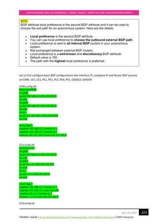
187April 24, 2020
Path ? Redistributed Networks
Weight = 32768 for LOCALLY ORIGINATED
Weight = 0 externally originated routes
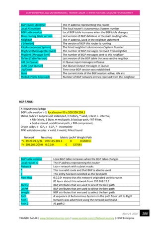
BGP ROUTING TABLE:
ATTR26#show ip route bgp
Codes: L - local, C - connected, S - static, R - RIP, M - mobile, B - BGP
D - EIGRP, EX - EIGRP external, O - OSPF, IA - OSPF inter area
N1 - OSPF NSSA external type 1, N2 - OSPF NSSA external type 2
E1 - OSPF external type 1, E2 - OSPF external type 2
i - IS-IS, su - IS-IS summary, L1 - IS-IS level-1, L2 - IS-IS level-2
ia - IS-IS inter area, * - candidate default, U - per-user static route
o - ODR, P - periodic downloaded static route, H - NHRP, l - LISP
+ - replicated route, % - next hop override
Gateway of last resort is not set
29.0.0.0/24 is subnetted, 1 subnets
B 29.29.29.0 [20/0] via 209.165.201.1, 00:05:03
B This route was learned through BGP
29.29.29.0/24 Destination learn network and 24 is subnet mask
20 20 is the Administrative Distance of eBGP protocol
209.165.201.2 Next Hop IP Address where to send the traffic
00:05:03 Time since the route was learnt
Now let us take debug captures for BGP packets:
VODAFONER28# debug ip bgp topology *
*Sep 17 11:42:57.311: %BGP-5-ADJCHANGE: neighbor 10.172.13.1 Up
*Sep 17 11:43:02.431: BGP(0): 10.172.13.1 rcvd UPDATE w/ attr: nexthop 10.172.13.1, origin i,
localpref 100, metric 0
*Sep 17 11:43:02.435: BGP(0): 10.172.13.1 rcvd 29.29.29.0/24
*Sep 17 11:43:02.435: BGP(0): 10.172.13.1 rcvd UPDATE w/ attr: nexthop 209.165.201.2, origin i,
localpref 100, metric 0, merged path 65000, AS_PATH
*Sep 17 11:43:02.439: BGP(0): 10.172.13.1 rcvd 209.209.209.0/24
*Sep 17 11:43:03.359: BGP(0): no valid path for 209.209.209.0/24
*Sep 17 11:43:03.359: BGP(0): Revise route installing 1 of 1 routes for 29.29.29.0/24 ->
10.172.13.1(global) to main IP table
*Sep 17 11:43:03.359: BGP(0): no valid path for 209.209.209.0/24
*Sep 17 11:43:08.355: BGP(0): no valid path for 209.209.209.0/24](https://image.slidesharecdn.com/ccnpenterpriseworkbookv1-201010132734/85/Ccnp-enterprise-workbook-v1-0-completed-till-weigth-187-320.jpg)

![Ccnp presentation [Day 1-3] Class](https://cdn.slidesharecdn.com/ss_thumbnails/ccnppresentation-day1-3demo-200416075108-thumbnail.jpg?width=640&height=640&fit=bounds)