Download as PDF, PPTX


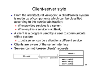
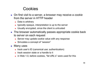
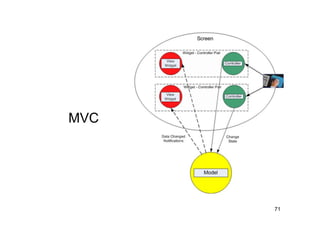
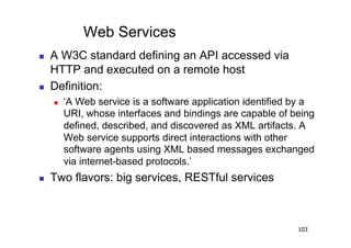
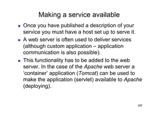
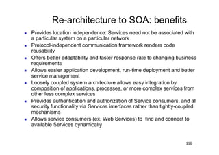
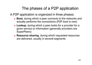
![A Conversation With a Web Server
GET /index.html HTTP/1.0
User-Agent: Mozilla/4.73 [en] (X11;HTTP method & URIi686)
U; Linux 2.0.35
Host: www.yahoo.com
Accept: image/gif, image/x-xbitmap, image/jpeg, image/pjpeg,
image/png, */*
Accept-Language: en
Accept-Charset: iso-8859-1,*,utf-8
Server replies:
HTTP/1.0 200 OK Cookie data: up to
Content-Length: 16018 4KiB
Set-Cookie: B=2vsconq5p0h2n
Content-Type: text/html
MIME content type
<html><head><title>Yahoo!</title><base href=http://www.yahoo.com/>
…etc.
Repeat for embedded content (images, stylesheets, scripts...)
<img width=230 height=33 src="http://us.a1.yimg.com/
us.yimg.com/a/an/anchor/icons2.gif">
57](https://image.slidesharecdn.com/3-110216035317-phpapp01/85/3-57-320.jpg)

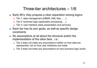
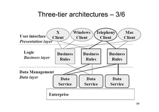
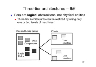
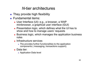
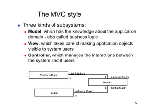
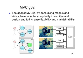
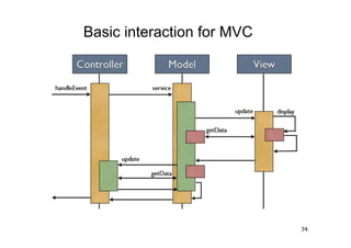
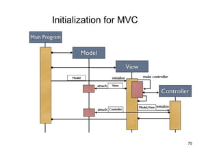
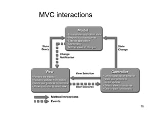
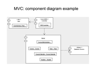
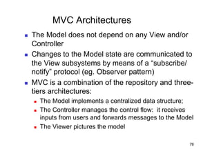
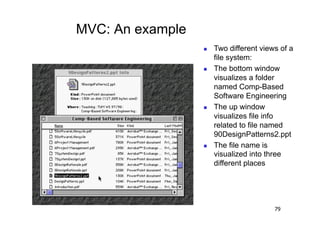
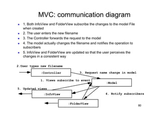
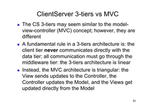


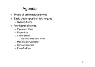
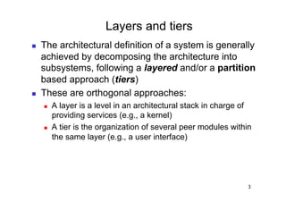
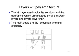
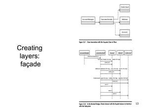
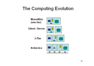
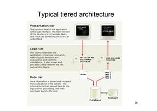
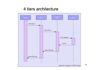
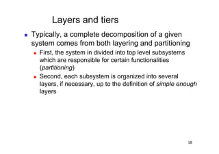
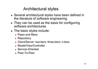
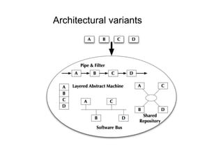
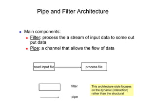
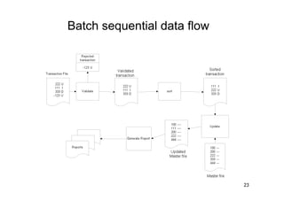
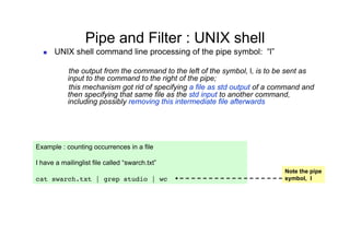
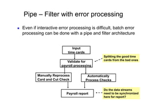
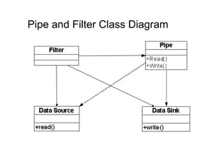
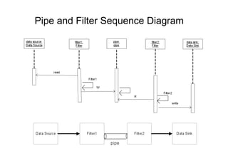
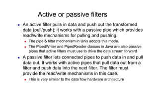
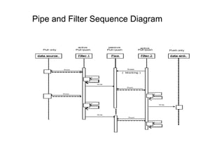
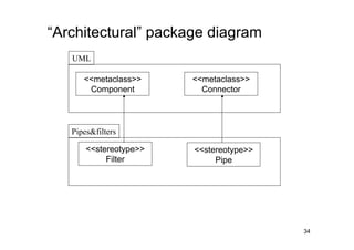
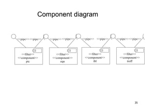
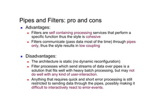
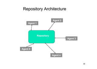
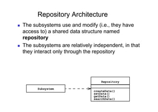
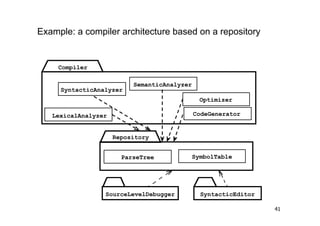
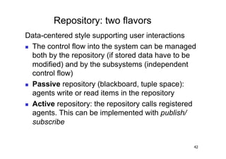
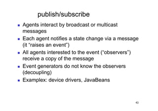
The document discusses architectural styles and decomposition techniques. It describes layers as hierarchical sets of subsystems that provide related services by utilizing underlying layers. Tiers partition a system into peer subsystems responsible for classes of services. Common architectural styles include pipes and filters, repository, client/server, model-view-controller, service-oriented, and peer-to-peer. Layers and tiers are often combined for complete decomposition, with subsystems divided into tiers and each tier organized into layers. The pipe and filter style focuses on dynamic interaction by processing data streams through filters connected by pipes.