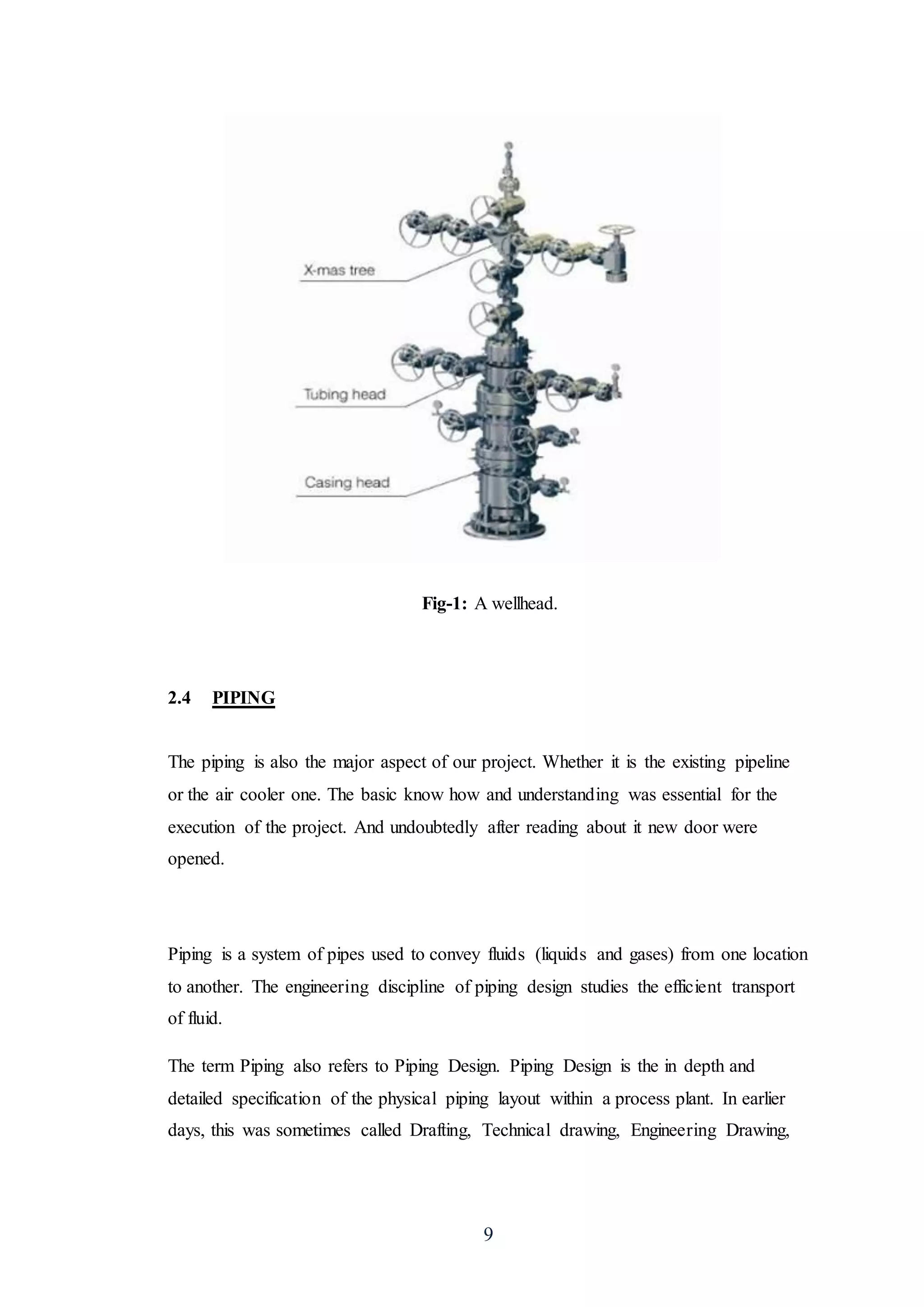
This document provides an overview of a project to install an air cooler on an existing well head facility. It discusses the project scope, aims, and objectives which are to reduce costs by allowing gas transfer through carbon steel piping using an air cooler. It then describes research conducted on air coolers, the different types including shell and tube, plate, regenerative, and adiabatic wheel heat exchangers. Finally, it discusses wellheads, their main components such as the casing head, tubing head, and Christmas tree, and their functions in regulating extraction of hydrocarbons from underground formations.
This manual covers the basic guidelines and minimum requirements for
periodic inspection of heat exchangers used in petroleum refinery.
Locations to be inspected, inspection tools, frequency of inspection &
testing, locations prone to deterioration and causes, corrosion
mitigation, inspection and testing procedures have been specified in
the manual.
Documentation of observations & history of heat exchangers,
inspection checklist and recommended practices have also been
included.
Heat exchanging equipment is used for heating or cooling a fluid.
Individual heat transfer equipment is named as per its function.
Cooler
A cooler cools the process fluid, using water or air, with no change of
phase.
Chiller
A chiller uses a refrigerant to cool process fluid to a temperature below
that obtainable with water.
Condenser
A condenser condenses a vapour or mixture of vapours using water or
air.
Exchanger
An exchanger performs two functions in that it heats a cold process
fluid by recovering heat from a hot fluid, which it cools. None of the
transferred heat is lost.
A cooling tower is a heat rejection device which extracts waste heat to the atmosphere through the cooling of a water stream to a lower temperature.
A cooling tower is a heat rejection device which extracts waste heat to the atmosphere through the cooling of a water stream to a lower temperature. Cooling towers may either use the evaporation of water to remove process heat and cool the working fluid to near the wet-bulb air temperature or, in the case of closed circuit dry cooling towers, rely solely on air to cool the working fluid to near the dry-bulb air temperature.
Common applications include cooling the circulating water used in oil refineries, petrochemical and other chemical plants, thermal power stations and HVAC systems for cooling buildings. The classification is based on the type of air induction into the tower: the main types of cooling towers are natural draft and induced draft cooling towers.
Cooling towers vary in size from small roof-top units to very large hyperboloid structures (as in the adjacent image) that can be up to 200 metres (660 ft) tall and 100 metres (330 ft) in diameter, or rectangular structures that can be over 40 metres (130 ft) tall and 80 metres (260 ft) long. The hyperboloid cooling towers are often associated with nuclear power plants,[1] although they are also used to some extent in some large chemical and other industrial plants. Although these large towers are very prominent, the vast majority of cooling towers are much smaller, including many units installed on or near buildings to discharge heat from air conditioning.
Cooling Tower: Types and performance evaluation, Efficient system operation, Flow control strategies and energy saving opportunities, Assessment of cooling towers
Heat transfer equipment is defined by the function it fulfills in a process. On the similar path, Heat exchangers are
the equipment used in industrial processes to recover heat between two process fluids. They are widely used in space
heating, refrigeration, air conditioning, power plants, chemical plants, petrochemical plants, petroleum refineries, and
natural gas processing. The operating efficiency of these exchangers plays a very key role in the overall running cost
of a plant. So the designers are on a trend of developing heat exchangers which are highly efficient, compact, and cost
effective.
PRINCIPAL OF COOLING TOWER
TYPES OF COOLING TOWER
DIFFERENT TERMS USED IN COOLING TOWER SPECIFICATION
AIR PROPERTIES AND
SIZING OF COOLING TOWER HEIGHT
TYPICAL SPECIFICATION FORMAT / DATASHEET
Type of heat exchanger. Which is mainly used in food industries, like dairy plant, for the pasturization, heat treatment of the beavrages or liquid raw material.
Ijri te-03-011 performance testing of vortex tubes with variable parametersIjripublishers Ijri
Conventional refrigeration system is a type of refrigeration systems which are costly; noisy, harmful gases released from a machine based on application of this type of system and it is required more maintenance. So, we need to go for unconventional refrigeration systems like vortex tube refrigeration system, which produce less vibrations and which require less maintenance and which are noiseless. It is required for our mechanical engineers to look for enhancing the performance of such vortex tubes. So as a part of my project work, I have chosen various sizes of vortex tubes and test their performances for finding out optimum performance. We will be testing the performance of vortex tubes with different ‘l/d’ ratios and different cold fractions, with different pressures and different nozzle sizes.
Heat Transfer Analysis to Optimize The Water Cooling Scheme For Combustion De...IJERA Editor
Thermal Propulsion system is one kind of propulsion system which is used to drive torpedo. The present study focuses mainly on design of combustion device known to be thrust chamber or thrust cylinder. The chamber and nozzle wall and the injector face plate must be made of metals selected for high strength at elevated temperature coupled with good thermal conductivity, resistance to high temperature oxidation. chemical inertness on the coolant on the coolant side, and suitability for the fabrication method to be employed. In the case of certain monopropellants, the metal must not catalyze the decomposition. Although aluminum and copper alloys have been used successfully for combustion chambers and nozzles, stainless steels and carbon steels are in widest use today.A cooling jacket permits the circulation of a coolant, which, in the case of flight engines is usually one of the propellants. Water is the only coolant recommended. The cooling jacket consists of an inner and outer wall. The combustion chamber forms the inner wall and another concentric but larger cylinder provides the outer wall. The space between the walls serves as the coolant passage. The nozzle throat region usually has the highest heat transfer intensity and is, therefore, the most difficult to cool.
ONGC Training on Heat Exchangers, Compressors & PumpsAkansha Jha
Plant overview, working of compressors, pumps, cooling towers, gas turbines.
Mini- Project on shell & tube type heat exchangers in ONGC, Uran plant. Hence,
calculating the effectiveness of heat exchanger using the working data.
Final report on spent solution in hydroprateekj765
Assessment of cooling towers, cooling tower efficiency, assessment of cooling towers fans, material required, maintenance operations, calculation of flow rate of spent
A heat pipe heat exchanger is a simple device which is made use of to transfer heat from one location to another, using an evaporation-condensation cycle.
1. 1
Burhan Ahmed IM-033
Manufacturing Engineering Project
(IM-409)
Title…………………………………………………
…………………………………………………….
Department of Industrial & Manufacturing (IMD)
NED University of Engineering & Technology
2. 2
CHAPTER 1
1 INTRODUCTION
The primary necessity in today’s mechanized world is energy. The uninterrupted and
economical supply of energy is a unanimous objective. This project deals with the
standards and procedures followed in industries for the placement of a well head
cooler.
1.1 PROJECT SCOPE:
The project will be of a placement of Air Cooler in existing well head facility and its
piping tie-in with the existing well head flow-line and vent (by using software
AutoCAD). Furthermore, stress analysis of cooler piping will be performed on
software CAESAR for checking of thermal loads within allowable limit of code
(ASME B 31.3 and B31.8) and nozzle loadings of Air Cooler as per API 661.
In Scope: Out of Scope:
1. Study is to design network on
existing well head pipeline.
1. The fabrication of pipeline
2. It Will include report of stress
analysis and Design Drawings.
2. Finite Element Analysis of pipeline
3. Well head piping
3. 3
1.2 AIMS AND OBJECTIVES:
The cost is the primary concern in every industry. If the project does not result in
profit it is deemed useless. Similarly if the transportation cost supersedes selling cost
the exploration has no point and well would be closed.
Normal Carbon steel grades cannot be used for the transmission of a gas obtained
from a reservoir due to its high temperature and pressure and the transportation of the
gas on duplex results in a budgeting nightmare.
Therefore, the aim of the project is to reduce the cost that would result in case of
duplex steel pipeline. For the solution of this problem Air Cooler comes into play. It
provides the opportunity of gas transfer on a carbon steel thus reducing cost.
4. 4
CHAPTER 2
2 RESEARCH AND STUDY
2.1 AIR COOLER
The first and foremost of the term encountered while tackling with the project was Air
cooler/Heat Exchanger as it is the basic component that will be installed upon the
existing well head pipeline.
Definition:
To define it in the simplest way, A heat exchanger is a piece of equipment built for
efficient heat transfer from one medium to another.
Heat exchangers for the compressor to operate efficiently, gas temperature should be
low. The lower the temperature, the less energy will be used to compress the gas for
the given final pressure and temperature. However, both gas from separators and
compressed gas are relatively hot. When gas is compressed, it must remain in
thermodynamic balance, which means that the gas pressure times the volume over the
temperature (PV/T) must remain constant. (PV = nkT). This ends up as a temperature
increase.
2.2 DIFFERENT TYPES OF HEAT EXCHANGERS
Followingare differenttypesof heatexchangers:
2.2.1 SHELL AND TUBE TYPE
Tube and shell exchangers place tubes inside a shell filled with cooling fluid. The
cooling fluid is often pure water with corrosion inhibitors. When designing the
process, it is important to plan the thermal energy balance. Heat should be conserved,
e.g., by using the cooling fluid from the gas train to reheat oil in the oil train.
To be able to transfer heat well, the tube material should have good thermal
conductivity. Because heat is transferred from a hot to a cold side through the tubes,
there is a temperature difference through the width of the tubes. Because of the
5. 5
tendency of the tube material to thermally expand differently at various temperatures,
thermal stresses occur during operation. This is in addition to any stress from high
pressures from the fluids themselves. The tube material also should be compatible
with both the shell and tube side fluids for long periods under the operating conditions
(temperatures, pressures, pH, etc.) to minimize deterioration such as corrosion. All of
these requirements call for careful selection of strong, thermally-conductive,
corrosion-resistant, high quality tube materials, typically metals, including copper
alloy, stainless steel, carbon steel, non-ferrous copper alloy, Inconel, nickel, Hastelloy
and titanium. Fluoropolymers such as Perfluoroalkoxy alkane (PFA) and Fluorinated
ethylene propylene (FEP) are also used to produce the tubing material due to their
high resistance to extreme temperatures. Poor choice of tube material could result in a
leak through a tube between the shell and tube sides causing fluid cross-contamination
and possibly loss of pressure.
2.2.2 PLATE HEAT EXCHANGER
Heat exchangers of various forms are used to cool the gas. Plate heat exchangers
consist of a number of plates where the gas and cooling medium pass between
alternating plates in opposing directions. Plate heat exchangers consist of thin plates
joined together, with a small amount of space between each plate, typically
maintained by a small rubber gasket. The surface area is large, and the corners of each
rectangular plate feature an opening through which fluid can flow between plates,
extracting heat from the plates as it flows. The fluid channels themselves alternate hot
and cold fluids, meaning that heat exchangers can effectively cool as well as heat
fluid—they are often used in refrigeration applications. Because plate heat exchangers
have such a large surface area, they are often more effective than shell and tube heat
exchangers.
2.2.3 REGENERATIVE HEAT EXCHANGER
6. 6
In a regenerative heat exchanger, the same fluid is passed along both sides of the
exchanger, which can be either a plate heat exchanger or a shell and tube heat
exchanger. Because the fluid can get very hot, the exiting fluid is used to warm the
incoming fluid, maintaining a near constant temperature. A large amount of energy is
saved in a regenerative heat exchanger because the process is cyclical, with almost all
relative heat being transferred from the exiting fluid to the incoming fluid. To
maintain a constant temperature, only a little extra energy is need to raise and lower
the overall fluid temperature.
2.2.4 ADIABATIC WHEEL HEAT EXCHANGER
In this type of heat exchanger, an intermediate fluid is used to store heat, which is
then transferred to the opposite side of the exchanger unit. An adiabatic wheel
consists of a large wheel with threads that rotate through the fluids—both hot and
cold—to extract or transfer heat.
2.3 WELLHEAD
Although the project doesn’t revolve completely around the Well head but it is of
important. Since the piping system (under consideration) is initiated from it. One
cannot understand a system if he/she doesn’t know about all the components of it. It
was needed to learn about it.
Position:
The wellhead sits on top of the actual oil or gas well leading down to the reservoir. A
wellhead may also be an injection well, used to inject water or gas back into the
reservoir to maintain pressure and levels to maximize production.
Once a natural gas or oil well is drilled and it has been verified that commercially
viable quantities of natural gas are present for extraction, the well must be
“completed” to allow petroleum or natural gas to flow out of the formation and up to
the surface. This process includes strengthening the well hole with casing, evaluating
7. 7
the pressure and temperature of the formation, and installing the proper equipment to
ensure an efficient flow of natural gas from the well. The well flow is controlled with
a choke.
We differentiate between, dry completion (which is either onshore or on the deck of
an offshore structure) and subsea completions below the surface. The wellhead
structure, often called a Christmas tree, must allow for a number of operations relating
to production and well workover. Well workover refers to various technologies for
maintaining the well and improving its production capacity.
Wellheads can involve dry or subsea completion. Dry completion means that the well
is onshore or on the topside structure on an offshore installation. Subsea wellheads are
located underwater on a special sea bed template. The wellhead has equipment
mounted at the opening of the well to regulate and monitor the extraction of
hydrocarbons from the underground formation. This also prevents oil or natural gas
leaking out of the well, and prevents blow-outs due to high pressure formations.
Formations that are under high pressure typically require wellheads that can withstand
a great deal of upward pressure from the escaping gases and liquids. These must be
able to withstand pressures of up to 140 MPa (1,400 Bar). The wellhead consists of
three components: the casing head, the tubing head, and the “Christmas tree.”
2.3.1 Main components
Following are the main components of a Wellhead.
2.3.1.1 Casing head
In oil drilling, a casing head is a simple metal flange welded or screwed onto
the top of the conductor pipe (also known as drive-pipe) or the casing and
forms part of the wellhead system for the well.
8. 8
This is the primary interface for the surface pressure control equipment, for
example blowout preventers (for well drilling) or the Christmas tree (for well
production).
The casing head, when installed, is typically tested to very strict pressure and
leak-off parameters to insure viability under blowout conditions, before any
surface equipment is installed.
2.3.1.2 Tubing head:
Tubing head is a wellhead component that supports the tubing hanger and
provides a means of attaching the Christmas tree to the wellhead.
2.3.1.3 Christmas Tree:
The primary function of a tree is to control the flow, usually oil or gas, out of
the well. (A tree may also be used to control the injection of gas or water into
a non-producing well in order to enhance production rates of oil from other
wells.) When the well and facilities are ready to produce and receive oil or
gas, tree valves are opened and the formation fluids are allowed to go through
a flow line.
A tree often provides numerous additional functions including chemical
injection points, well intervention means, pressure relief means, monitoring
points (such as pressure, temperature, corrosion, erosion, sand detection, flow
rate, flow composition, valve and choke position feedback), and connection
points for devices such as down hole pressure and temperature transducers.
9. 9
Fig-1: A wellhead.
2.4 PIPING
The piping is also the major aspect of our project. Whether it is the existing pipeline
or the air cooler one. The basic know how and understanding was essential for the
execution of the project. And undoubtedly after reading about it new door were
opened.
Piping is a system of pipes used to convey fluids (liquids and gases) from one location
to another. The engineering discipline of piping design studies the efficient transport
of fluid.
The term Piping also refers to Piping Design. Piping Design is the in depth and
detailed specification of the physical piping layout within a process plant. In earlier
days, this was sometimes called Drafting, Technical drawing, Engineering Drawing,
10. 10
and Design but is today commonly performed by Designers who are excelled in
Computer Aided Design (CAD) software.
Pipelines transport gas or liquid, and are fed from the high pressure compressors or
pumps. One or more compressor stations are needed to keep the required gas flow in
the pipeline. Internal friction will cause a pressure drop along the pipeline that
increases with flow. Thus, the starting pressure must be high enough to maintain
design capacity flow up to the final terminal. If this is not practically possible,
additional compressor stations are needed along the total length. Typical starting
pressure is about 150-250 bar (15-25 MPa). The final pressure can be as low as 50 bar
(5 MPa) at the pipeline terminal end.
The material with which a pipe is manufactured often forms as the basis for choosing
any pipe. Materials that are used for manufacturing pipes include:
Carbon steel
Low temperature service carbon steel
Stainless steel
Nonferrous metals, e.g. cupro-nickel
Nonmetallic, e.g. tempered glass
2.4.1 Types of pipes used in Oil & gas industries
2.4.1.1 Duplex Steel:
Duplex is a stainless steel made from a mixture of austenite and ferrite phases.
Like most austenitic stainless steels, duplex has a strong resistance to corrosion.
Unlike similar steels, duplex also displays an improved resistance to localized
corrosion, particularly pitting, crevice corrosion and stress corrosion cracking.
And because duplex has a lower nickel and molybdenum content than other
austenitic stainless steels, it can prove a more cost effective option due to a
lower alloying content.
11. 11
Due to its ferretic qualities, duplex steel also shows very good resistance to
stress corrosion cracking when compared to standard austenitics. In some cases,
the strength of duplex steel can be up to double that of the most commonly used
grades of stainless steel.
Duplex becomes brittle at extreme temperatures so its use is normally restricted
to a maximum temperature of 300 degrees. Duplex also shows signs of
embrittlement at –50 degrees.
Benefits:
o Stronger than 300 series stainless steel which also brings weight
advantages.
o Cheaper than some stainless steels.
o High resistance to pitting, crevice corrosion and stress corrosion cracking.
o Higher heat conductivity and lower thermal expansion than austenitic
steels.
Uses:
o Pipes for production and transportation of oil and gas
o Structural and mechanical components
o Heat exchangers
o Cooling pipes
o Cargo vessels and containers
o High strength wiring
2.4.1.2 Super Duplex Steels
Super duplex is a stainless steel mainly used in oil and gas applications.
Due to a very high tensile strength, super duplex has better resistance to erosion,
corrosion cracking and corrosion fatigue than conventional austenitic stainless steels.
Its high concentration of chromium and Molybdenum content also gives super duplex
a high resistance to acids that might cause pitting and crevice corrosion. This makes
super duplex well suited for use in many onshore and offshore applications.
12. 12
Because super duplex is an austenitic ferritic iron chromium-Nickel Alloys with
Molybdenum addition, it is also used for industrial processes where high strength and
corrosion resistance are essential.
Structural and mechanical components, heat exchangers, utility and industrial
systems, cargo vessels and high strength wiring solutions are all ideal uses for super
duplex.
Benefits:
Super duplex is a stainless steel mainly used in oil and gas applications.
Due to a very high tensile strength, super duplex has better resistance to erosion,
corrosion cracking and corrosion fatigue than conventional austenitic stainless steels.
Its high concentration of chromium and Molybdenum content also gives super duplex
a high resistance to acids that might cause pitting and crevice corrosion. This
makes super duplex well suited for use in many onshore and offshore applications.
Because super duplex is an austenitic ferritic iron chromium-Nickel Alloys with
Molybdenum addition, it is also used for industrial processes where high strength and
corrosion resistance are essential.
Structural and mechanical components, heat exchangers, utility and industrial
systems, cargo vessels and high strength wiring solutions are all ideal uses for super
duplex.
Benefits:
o High strength
o Resistance to corrosion
o Resistance to erosion
o High-energy absorption
o High thermal conductivity
o Low thermal expansion
13. 13
Uses:
o Pipes for production and transportation of oil and gas
o Structural and mechanical components
o Heat exchangers
o Cooling pipes
o Cargo vessels and containers
o High strength wiring
2.4.1.3 Super duplex Stainless steels
Stainless steel is a steel alloy containing a minimum of 11% chromium. There are a
number of different types of stainless steels based on changes to its crystalline
structure. When nickel is added, the austenite structure is stabilised, making steel that
is non-magnetic and less brittle at low temperatures. Likewise, the addition of carbon
makes stainless steels stronger.
Austenitic stainless steels count for over 70% of all production. These super duplex
stainless steels contain enough nickel or manganese to retain their structure at all
temperatures between freezing and melting points.
Superaustenitic steel has a higher nickel content ensuring a greater resistance to stress
corrosion cracking. The addition of nitrogen and molybdenum also ensures a greater
resistance to chloride pitting and crevice corrosion. Low carbon versions of
superaustenitic steel avoid corrosion problems caused by welding. Because of the
increased alloys, superaustenitic steels are more expensive than austenitic steels.
Ferritic stainless steels have a greater resistance to corrosion but are less durable than
austenitic steels.
Martensitic stainless steels are extremely strong, durable and easy to manipulate by
machine. Martensitic steels are also less resistant to corrosion then austenitic and
14. 14
ferritic steels. Precipitation hardened martensitic steels on the other hand, are
comparable to austenitic and ferritic steels in terms of corrosion resistance, but are
also tougher than standard martensitic grades.
Duplex stainless steels have an equal mixture of austenite and ferrite phases. Due to
its ferretic qualities, duplex steel also shows very good resistance to stress corrosion
cracking when compared to standard austenitic steels.
2.4.1.4 Nickel alloys
Nickel is a versatile element that will bond with most alloys. Properties of nickel
include heat and corrosion resistance, electrical and magnetic capabilities, and low
expansion. Because of its versatility and natural properties, nickel is used to make a
number of alloys with a range of different commercial uses.
Nickel alloys offer excellent resistance to corrosion in seawater. As such it is widely
used in marine hardware. By altering the proportions of nickel and copper it is also
possible to change the electrical resistance of the alloy.
Nickel-chromium and nickel-chromium-iron alloys are resistant to high temperatures
and offer greater strength. They form the basis of many commercial and military
power systems. Nickel-chromium-iron alloys also offer a greater resistance to
corrosion in high-temperature, petrochemical environments.
Nickel-iron low-expansion alloys are designed to remain unaffected by a range of
temperatures. Such alloys are often used to make seals and precisions spring.
Soft magnetic alloys are created to have a wide range of magnetic properties in
relation to their nickel content. Alloys with high nickel content have a high
permeability but low saturation.
Welding products for Nickel Alloys are of a similar composition to the base metals
with the addition of elements to over-come any malleability problems.
15. 15
2.4.1.5 6% Molybdenum
6% Moly alloys are named for their 6% molybdenum content. Molybdenum is a
silvery metal with the sixth highest melting point of any element. It is therefore often
used in applications that involve intense heat. 6% Moly alloys also contain high levels
of chromium and nitrogen, which also make them highly resistant to corrosion.
Because of these characteristics, 6% Moly alloys are used in high chloride
environments and process streams, such as in sea and brackish water, pulp mill bleach
systems, desalination systems and chemical processes.
6% Moly alloys have excellent impact toughness and workability and are up to 50%
stronger than the 300 series austenitic steels. In addition, 6% Moly alloys are also
more cost effective than titanium and nickel based alloys.
Benefits:
o Very high resistance to chloride corrosion
o Stronger than austenitic stainless steels
o High melting point
Uses:
o Pulp Mill Bleach Systems
o Desalination Equipment
o Seawater handling equipment
o Chemical processing equipment
2.5 STRESS ANALYSIS
16. 16
As the next phase of the project is mostly centered around the stress analysis of the
piping network so the literature and research papers regarding this stress analysis and
its different techniques was read by the group.
Piping Stress analysis is a term applied to calculations, which address the static and
dynamic loading resulting from the effects of gravity, temperature changes, internal
and external pressures, changes in fluid flow rate and seismic activity. Codes and
standards establish the minimum requirements of stress analysis.
Stress analysis is specifically concerned with solid objects. The fundamental problem
in stress analysis is to determine the distribution of internal stresses throughout the
system, given the external forces that are acting on it. Piping stress analysis is a
discipline which is highly interrelated with piping layout and support design. The
layout of the piping system should be performed with the requirements of piping
stress and pipe supports in mind (i.e., sufficient flexibility for thermal expansion;
proper pipe routing so that simple and economical pipe supports can be constructed;
and piping materials and section properties commensurate with the intended service,
temperatures, pressures. There are various failure modes which could affect a piping
system. The piping engineer can provide protection against some of these failure
modes by performing stress analysis according to the piping codes.
When very hot gases flow out of the wellhead reservoirs, the piping systems designed
to accommodate all the stress and pressure has to be withstanding. Therefore, before
installing the piping, it is first analyzed in terms of stress and thermal load. To do that,
different software are used to perform testing and analysis if the material is strong
enough to withstand the ever increasing loads. CAESAR is mostly used to perform
this job and in our project, we have planned to make it useful to us as well.
Stress Terms:
2.5.1 Code stresses:
"Code stresses" are those that are specifically addressed by the Code. The B31
Pressure Piping Codes address the BENDING stresses (and torsional stresses) due to
thermal expansion/contraction and they also address the longitudinal BENDING
17. 17
stress (due to weight) added to the longitudinal pressure stress (the sum of these
stresses is called the "sustained stresses" or the "additive stresses").
As you point out, If a designer were to analyze a system that had a straight piece of
pipe between two rigid anchors, the Code equations would not address the resulting
stress in the pipe because it is not a bending stress - it is a compressive buckling
stress.
2.5.2 Types of stresses
Following are some types of stresses:
2.5.2.1 Axial Stress:
A stress that tends to change the length of a body. It could be compressive or tensile.
2.5.2.2 Bending Stress:
Stresses introduced by bending moment are called bending stress. They are indirect
normal stress. For engineering problems the material is considered isentropic and
homogenous.
2.5.2.3 Torsional Stress:
In the field of solid mechanics, torsion is the twisting of an object
due to an applied torque.
2.5.2.4 Hoop stress:
Circumferential stress or hoop stress, a normal stress in the tangential (azimuth)
direction; Axial stress, a normal stress parallel to the axis of cylindrical symmetry;
Radial stress, a stress in directions coplanar with but perpendicular to the symmetry
axis.
2.5.3 Maximum Stress Intensity:
18. 18
In ASME B31.8, we know that the strength criteria are listed as ratios of SMYS
(Specified Minimum Yield Strength), they are hoop stress is 0.72, combined stress is
0.9, and longitudinal stress is 0.8.
In the output of stress extended, two terms are shown, Maximum stress intensity and
code stress intensity. According to documentation, it appears the Maximum stress
intensity refers to maximum shear stress yielding. But how it is connected to
combined stress limit in ASME B31.8.
These two stresses appear very close to each other at each node in my model. Thus we
can assume the maximum stresses of these two kinds should be close and refer to the
same node. But in the highest stresses summary, they are quite different.
2.5.4 Static Load:
Dead loads are static forces that are relatively constant for an extended time. They
can be in tension or compression. The term can refer to a laboratory test method or to
the normal usage of a material or structure. Live loads are usually unstable or moving
loads.
2.5.5 Valve:
A valve is a device that regulates, directs or controls the flow of a fluid (gases,
liquids, fluidized solids, or slurries) by opening, closing, or partially obstructing
various passageways.
2.5.5.1 Ball Valve:
a one-way valve that is opened and closed by pressure on a ball which fits into a cup-
shaped opening.
2.5.5.2 Globe Valve:
A Globe valves is a linear motion valve and are primarily designed to stop, start and
regulate flow. The disk of a Globe valve can be totally removed from the flowpath or
it can completely close the flowpath. Conventional Globe valves may be used for
isolation and throttling services.
19. 19
2.6 P&ID
A piping and instrumentation diagram/drawing (P&ID) is a diagram in the process
industry which shows the piping of the process flow together with the installed
equipment and instrumentation.
Contents and functions of the P&IDs:
A piping and instrumentation diagram/drawing (P&ID) is defined as
A diagram which shows the interconnection of process equipment and the
instrumentation used to control the process. In the process industry, a standard set of
symbols is used to prepare drawings of processes. The instrument symbols used in
these drawings are generally based on International Society of Automation (ISA)
Standard S5. 1.
The primary schematic drawing used for laying out a process control installation.
P&IDs play a significant role in the maintenance and modification of the process that
it describes. It is critical to demonstrate the physical sequence of equipment and
systems, as well as how these systems connect. During the design stage, the diagram
also provides the basis for the development of system control schemes, allowing for
further safety and operational investigations, such as a Hazard and operability study
commonly pronounced as HAZOP.
2.7 Hydrotest:
A hydrostatic test is a way in which pressure vessels such as pipelines, plumbing, gas
cylinders, boilers and fuel tanks can be tested for strength and leaks. The test involves
20. 20
filling the vessel or pipe system with a liquid, usually water, which may be dyed to
aid in visual leak detection, and pressurization of the vessel to the specified test
pressure. Pressure tightness can be tested by shutting off the supply valve and
observing whether there is a pressure loss. The location of a leak can be visually
identified more easily if the water contains a colorant. Strength is usually tested by
measuring permanent deformation of the container. Hydrostatic testing is the most
common method employed for testing pipes and pressure vessels. Using this test helps
maintain safety standards and durability of a vessel over time. Newly manufactured
pieces are initially qualified using the hydrostatic test. They are then re-qualified at
regular intervals using the proof pressure test which is also called the modified
hydrostatic test. Testing of pressure vessels for transport and storage of gases is very
important because such containers can explode if they fail under pressure.
2.8 Pipeline testing:
Hydrotesting of pipes, pipelines and vessels is performed to expose defective
materials that have missed prior detection, ensure that any remaining defects are
insignificant enough to allow operation at design pressures, expose possible leaks and
serve as a final validation of the integrity of the constructed system. ASME B31.3
requires this testing to ensure tightness and strength.
Buried high pressure oil and gas pipelines are tested for strength by pressurizing them
to at least 125% of their maximum allowable working pressure (MAWP) at any point
along their length. Since many long distance transmission pipelines are designed to
have a steel hoop stress of 80% of specified minimum yield strength (SMYS) at
MAOP, this means that the steel is stressed to SMYS and above during the testing,
and test sections must be selected to ensure that excessive plastic deformation does
not occur.
Test pressures need not exceed a value that would produce a stress higher than yield
stress at test temperature. ASME B31.3 section 345.4.2 (c)
21. 21
Other codes require a more onerous approach. BS PD 8010-2 requires testing to 150%
of the design pressure - which should not be less than the MAOP plus surge and other
incidental effects that will occur during normal operation.
Leak testing is performed by balancing changes in the measured pressure in the test
section against the theoretical pressure changes calculated from changes in the
measured temperature of the test section.
2.9 Nozzles:
A nozzle is often a pipe or tube of varying cross sectional area, and it can be used to
direct or modify the flow of a fluid (liquid or gas). Nozzles are frequently used to
control the rate of flow, speed, direction, mass, shape, and/or the pressure of the
stream that emerges from them.
Flange: A flange is an external or internal ridge, or rim (lip), for strength, as the
flange of an iron beam such as an I-beam or a T-beam; or for attachment to another
object, as the flange on the end of a pipe, steam cylinder, etc., or on the lens mount of
a camera; or for a flange of a rail car or tram wheel.
2.9.1.1 Types of nozzles :
1. Jet
2. High velocity
3. Propelling
4. Magnetic
5. Spray
6. Vacuum
7. Shaping
22. 22
2.9.1.1.1 Jet
A gas jet, fluid jet, or hydro jet is a nozzle intended to eject gas or fluid in a coherent
stream into a surrounding medium. Gas jets are commonly found in gas stoves, ovens,
or barbecues. Gas jets were commonly used for light before the development of
electric light. Other types of fluid jets are found in carburetors, where smooth
calibrated orifices are used to regulate the flow of fuel into an engine, and in jacuzzis
or spas.
Another specialized jet is the laminar jet. This is a water jet that contains devices to
smooth out the pressure and flow, and gives laminar flow, as its name suggests. This
gives better results for fountains.
The foam jet is another type of jet which uses foam instead of a gas or fluid.Nozzles
used for feeding hot blast into a blast furnace or forge are called tuyeres.
Jet nozzles are also use in large rooms where the distribution of air via ceiling
diffusers is not possible or not practical. Diffusers that uses jet nozzles are called jet
diffuser where it will be arranged in the side wall areas in order to distribute air.
When the temperature difference between the supply air and the room air changes, the
supply air stream is deflected upwards, to supply warm air, or downwards, to supply
cold air.
2.9.1.1.2 High velocity
A rocket nozzle.Frequently, the goal of a nozzle is to increase the kinetic energy of
the flowing medium at the expense of its pressure and internal energy.
Nozzles can be described as convergent (narrowing down from a wide diameter to a
smaller diameter in the direction of the flow) or divergent (expanding from a smaller
23. 23
diameter to a larger one). A de Laval nozzle has a convergent section followed by a
divergent section and is often called a convergent-divergent nozzle ("con-di nozzle").
Convergent nozzles accelerate subsonic fluids. If the nozzle pressure ratio is high
enough, then the flow will reach sonic velocity at the narrowest point (i.e. the nozzle
throat). In this situation, the nozzle is said to be choked.
Increasing the nozzle pressure ratio further will not increase the throat Mach number
above one. Downstream (i.e. external to the nozzle) the flow is free to expand to
supersonic velocities; however Mach 1 can be a very high speed for a hot gas because
the speed of sound varies as the square root of absolute temperature. This fact is used
extensively in rocketry where hypersonic flows are required and where propellant
mixtures are deliberately chosen to further increase the sonic speed.
Divergent nozzles slow fluids if the flow is subsonic, but they accelerate sonic or
supersonic fluids.
Convergent-divergent nozzles can therefore accelerate fluids that have choked in the
convergent section to supersonic speeds. This CD process is more efficient than
allowing a convergent nozzle to expand supersonically externally. The shape of the
divergent section also ensures that the direction of the escaping gases is directly
backwards, as any sideways component would not contribute to thrust.
2.9.1.1.3 Propelling
A jet exhaust produces a net thrust from the energy obtained from combusting fuel
which is added to the inducted air. This hot air passes through a high speed nozzle, a
propelling nozzle, which enormously increases its kinetic energy.
24. 24
Increasing exhaust velocity increases thrust for a given mass flow, but matching the
exhaust velocity to the air speed provides the best energy efficiency. However,
momentum considerations prevent jet aircraft from maintaining velocity while
exceeding their exhaust jet speed. The engines of supersonic jet aircraft, such as those
of fighters and SST aircraft (e.g. Concorde) almost always achieve the high exhaust
speeds necessary for supersonic flight by using a CD nozzle despite weight and cost
penalties; conversely, subsonic jet engines employ relatively low, subsonic, exhaust
velocities and therefore employ simple convergent nozzle, or even bypass nozzles at
even lower speeds.
Rocket motors maximise thrust and exhaust velocity by using convergent-divergent
nozzles with very large area ratios and therefore extremely high pressure ratios. Mass
flow is at a premium because all the propulsive mass is carried with vehicle, and very
high exhaust speeds are desirable.
2.9.1.1.4 Magnetic
Magnetic nozzles have also been proposed for some types of propulsion, such as
VASIMR, in which the flow of plasma is directed by magnetic fields instead of walls
made of solid matter.
2.9.1.1.5 Spray
Many nozzles produce a very fine spray of liquids.
Atomizer nozzles are used for spray painting, perfumes, carburetors for internal
combustion engines, spray on deodorants, antiperspirants and many other similar
uses.
25. 25
Air-Aspirating Nozzle uses an opening in the cone shaped nozzle to inject air into a
stream of water based foam (CAFS/AFFF/FFFP) to make the concentrate "foam up".
Most commonly found on foam extinguishers and foam handlines.
Swirl nozzles inject the liquid in tangentially, and it spirals into the center and then
exits through the central hole. Due to the vortexing this causes the spray to come out
in a cone shape.
2.9.1.1.6 Vacuum
Vacuum cleaner nozzles come in several different shapes. Vacuum Nozzles are used
in vacuum cleaners.
2.9.1.1.7 Shaping
Some nozzles are shaped to produce a stream that is of a particular shape. For
example, extrusion molding is a way of producing lengths of metals or plastics or
other materials with a particular cross-section. This nozzle is typically referred to as a
die.
2.10 Restraints:
Dynamic restraints are specially designed to absorb sudden increase in load from the
pipe and transfer into the structure and to dampen any opposing oscillation between
the pipe and the structure. These restraints are not intended to carry the weight of pipe
work and should not impede the function of the supports. Dynamic restraints are
required to be very stiff, to have high load capacity and to minimize free movement
between pipe and structure. In general terms, a pipe support is designed to carry the
pipe weight while simultaneously permitting deflection in vertical and/or horizontal
directions. Whereas, restraints are intended to restrict movement as either a guiding
element or an anchoring device.
The main supports that make up the dynamic restraints for process piping are-
1. Sway Braces
27. 27
CHAPTER 3
3 STANDARDS
3.1 Code Requirements
There are various ASME and ANSI codes which govern the stress analysis of
different kinds of pressure piping. These codes contain basic reference data, formulas,
and equations necessary for piping design and stress analysis.
Each power plant is committed to a particular edition of a code for different types of
piping. For example, the nuclear Class 1, 2, and 3 piping of a power plant may be
committed to comply with the ASME Boiler and Pressure Vessel Code, Section III,
1974 edition, while the nonnuclear piping may be committed to ANSI B31.1 Power
Piping Code, 1973 edition.
3.2 Standards provide:
3.2.1 Safety and reliability
Adherence to standards helps ensure safety, reliability and environmental care.
As a result, users perceive standardized products and services as more dependable
this in turn raises user confidence, increasing sales and the take-up of new
technologies.
3.2.2 Support of government policies and legislation
Standards are frequently referenced by regulators and legislators for protecting
user and business interests, and to support government policies.
28. 28
3.2.3 Interoperability
The ability of devices to work together relies on products and services
complying with standards.
3.2.4 Business benefits
Standardization provides a solid foundation upon which to develop new
technologies and to enhance existing practices. Specifically standards:
o Open up market access
o Provide economies of scale
o Encourage innovation
o Increase awareness of technical developments and initiatives
3.2.5 Consumer choice
Standards provide the foundation for new features and options, thus
contributing to the enhancement of our daily lives. Mass production based on
standards provides a greater variety of accessible products to consumers.
3.3 ASME & API Codes:
In today’s world, standardization assures your quality. It insures that the design and
proposed idea is per safety and production requirement. No industry can work without
standardizing its procedures and operations. The target is to familiarize ourselves with
29. 29
the same standards that are applicable in the industries. The following two standards
will be applied by us on the project.
3.3.1 Standards employed in our project:
3.3.1.1 ASME B 31.8
ASME (American Society of Mechanical Engineers) standardizes many engineering
aspects. The B 31.8 code is for Pressure Piping. The code sets forth engineering
requirements deemed necessary for the safe and construction of pressure piping.
This Code covers the design, fabrication, installation, inspection, and testing of
pipeline facilities used for the transportation of gas. This Code also covers safety
aspects of the operation and maintenance of those facilities. It doesn’t cover the
designing and manufacturing of the pressure vessels which fall under the BPV codes.
The requirements of this Code are adequate for safety under conditions usually
encountered in the gas industry.
Description
ASME has been defining piping safety since 1922.
ASME’s B31.8 Gas Transmission and Distribution Piping Systems covers gas
transmission and distribution piping systems, including gas pipelines, gas compressor
stations, gas metering and regulation stations, gas mains, and service lines up to the
outlet of the customer’s meter set assembly. It includes gas transmission and
gathering pipelines, including appurtenances that are installed offshore for the
purpose of transporting gas from production facilities to onshore locations; gas
30. 30
storage equipment of the closed pipe type that is fabricated or forged from pipe or
fabricated from pipe and fittings; and gas storage lines.
Key changes to this revision include:
updating of gas treating facilities section;
updating of repair procedures for steel pipelines section;
addition of section on hazard analysis for offshore compressor stations;
updating of offshore test pressure section.
This Code prescribes comprehensive solutions for materials, design, fabrication,
assembly, erection, testing and inspection. It also serves as a companion to ASME’s
other B31 codes on piping systems. Together, they remain essential references for
anyone engaged with piping.
This Code prescribes comprehensive solutions for materials, design, fabrication,
assembly, erection, testing and inspection. It also serves as a companion to ASME’s
other B31 codes on piping systems. Together, they remain essential references for
anyone engaged with piping.
Careful application of these B31 codes will help users to comply with applicable
regulations within their jurisdictions, while achieving the operational, cost and safety
benefits to be gained from the many industry best-practices detailed within these
volumes.
Intended for manufacturers, users, constructors, designers, and others concerned with
the design,.
31. 31
3.3.1.2 API 661:
This standard gives requirements and recommendations for the design, materials,
fabrication, inspection, testing, and preparation for shipment of air-cooled heat
exchangers for use in the petroleum, petrochemical, and natural gas industries.
This standard is applicable to air-cooled heat exchangers with horizontal bundles, but
the basic concepts can be applied to other configurations.
This standard of American Petroleum Institute standardizes the heat exchanger that
will be termed as air cooler during our project and ensures the design and safety
requirements are as per best practices so that the quality is assured.
3.3.1.3 ASME B31.3
This code is related to process piping. During CAESAR run we used this standard for
the standardized process insurance.
3.3.1.4 ASME B16.5
This is the ASME code related to Pipe Flanges & Flanged Fittings. The stress analysis
was run according to this code for proper safety of flanges and fittings.
32. 32
Chapter 4
4 P & IDs
4.1 Introduction:
A piping and instrumentation diagram/drawing (P&ID) is a diagram in the process
industry which shows the piping of the process flow together with the installed
equipment and instrumentation.
P&IDs play a significant role in the maintenance and modification of the process that
it describes. It is critical to demonstrate the physical sequence of equipment and
systems, as well as how these systems connect. During the design stage, the diagram
also provides the basis for the development of system control schemes, allowing for
further safety and operational investigations, such as a Hazard and operability study
commonly pronounced as HAZOP.
The detailed study of P & ID enabled the understanding of the project. It established
the ground for working and served as the basis for the project. The overall Piping and
instrumentation drawing of the project is available on the next page.
33. 33
The study of the drawing showed us the border of the placement of the air cooler. The
design of the air cooler should suffice the instructions detailed in the drawing.
The cooler has to be placed between TW 730 and TW 731. To block the original flow
of the gas a double block and bleed valve is used. The flow is then to be directed
towards the Air Cooler and for safety purpose a double block and bleed is also
deployed there.
The gas now inside the Air Cooler is cooled and exited with lower temperature and
pressure. This is joined into the existing flow line through a pile. A connection is also
provided to the vent for excessive flow.
The next diagram exhibit the area concerned with our project.
34. 34
CHAPTER 5
5 BUDGETING
5.1 Introduction:
Since budgeting allows you to create a spending plan for your money, it ensures that
you will always have enough money for the things you need and the things that are
important to you. Following a budget or spending plan will also keep you out of debt
or help you work your way out of debt if you are currently in debt.
A cost estimate is the approximation of the cost of a program, project, or operation.
The cost estimate is the product of the cost estimating process. The cost estimate has a
single total value and may have identifiable component values.
This project was feasible only because the original costs were too high. This created
the necessity of a heat exchanger that enable the further transportation on a cheaper
pipeline for the cost reduction and increase of profit.
Normal Carbon steel grades cannot be used for the transmission of a gas obtained
from a reservoir due to its high temperature and pressure.
Therefore,
“The aim of the project is to reduce the cost of an existing duplex steel pipeline a
heat exchanger is installed so that for further transportation low cost carbon
steel can be used.”
Initial estimation of the project was based on the duplex steel. It is as follows:
35. 35
5.2 PIPING COST:
5.2.1 For Duplex Steel:
For a pipeline of 10 km:
Pipe per piece= 12 m
For total pipeline: 10000/12= 834 dia inches
Pipeline Cost Construction Cost Total Cost
Cost
per
mete
r
80,000 PKR 1800 PKR
Total 100008*1800=80,00,00,00
0 PKR
1800*834=15,01,20
0 PKR
80,00,00,000+15,01,20
0 =80,01,50,120 PKR
5.2.2 For Carbon Steel:
For a pipeline of 10 km:
Pipe per piece= 12 m
For total pipeline: 10000/12= 834 dia inches
Air Cooler cost: 12,00,00,000 PKR
Pipeline Cost Construction
Cost
Total Cost
Cost per
meter
5,000 PKR 800 PKR
Total 10000*5000=
5,00,00,000
PKR
800*834=
6,67,200 PKR
5,00,00,000+6,67,200+12,00,00,000=
17,06,67,200 PKR
36. 36
CHAPTER 6
6 LAYOUT DRAWING
6.1 Introduction:
Layout is basically a blueprint. In the project there are two kinds of drawing covered.
Equipment Layout
Piping Layout
6.2 Equipment Layout:
Equipment layout is just that - where pieces of equipment, such as displays and
controls, are laid out in relation to everything else around them, including the person
using them. It's important to get this layout right.
Good equipment layout helps to ensure that:
Equipment can be clearly identified
Equipment is easy and efficient to use
Errors are avoided, especially under emergency conditions
The following is the equipment layout drawing of the project. This indicates the
position of air cooler in relation with the wellhead facility. It clearly shows that air
cooler is placed within the safety constraints.
37. 37
6.3 Piping Layout:
Piping Layout is dimensional drawing showing plan of pipelines laying view between
starting and end points. This incorporates size of pipe (inches), thickness (in inch or
schedule), fitting detail, bend, elbow, tees, reducers, valves), elevation of piping
points and all details to lay pipe between two points in consideration. Piping layout
drawing can help Oil and Gas contractors visualize a given project and plant layout
design.
In the following piping layout drawing the routing was conducted in order to create a
path for the gas to flow into and out of the Air cooler. The essential block and bleed
valves as per the P & ID requirement were placed and the connection from vent of the
air cooler to the plant vent shown.
38. 38
CHAPTER 7
7 ISOMETRIC DRAWING
7.1 Introduction:
Piping isometric means isometric view of pipe line between two points in consideration. It is
drawn to the scale. Gives correct detail of Bill of Material needed for execution of the piping
job.
A pipe into a isometric view, is always drawn by a single line. This single line is the
centerline of the pipe, and from that line, the dimensions measured. So, not from the outside
of a pipe or fitting.
The following is the projects isometric drawing that served as the basis for the CESAR run
(Stress Analysis) and contains the Bill of Material.
39. 39
7.2 Bill of material
BILL OF MATERIAL
S
R
No
ITEM SIZE RATING/SC
H
ENDS DESCRIPTION
1 Pipe 6" SCH.40S BE ASTM A790 UNS S31803
2 Elbow 90
LR
6" SCH.40S BE ASTM A815 UNS 31803
3 Straight TEE 6" SCH.40S BE ASTM A815 UNS 31803
4 Weldolet 6" * 2" SCH.40S BE ASTM A182 GR.F51
5 Flange 2" 900#/SCH.40
S
WN
RTJ
ASTM A182 GR.F51
6 Elbow 90
LR
2" SCH.40S BE ASTM A815 UNS S31803
7 Weldolet 6" * 1" SCH.40S BE ASTM A182 GR.F51
8 Ball Valve 6" 900# RTJ BA470
9 Globe Valve 6" 900# RTJ GL445
10 Ball Valve 2" 900# RTJ BA470
11 Flange 6" 900#/SCH.40
S
WN
RTJ
ASTM A182 GR.F51
12 Blind Flange 2" 900# RTJ ASTM A182 GR.F51
13 Gasket 6" 900# RTJ OVAL RING UNS NO.8932
R45
14 Gasket 2" 900# RTJ OVAL RING UNS NO.8932
R24
15 Gasket 1/2" 900# RTJ OVAL RING UNS NO.8932
R12
16 Stud Bolt
with 3-HEX
nuts
1 1/8"
*
220m
m LG
- - BOLT: ASTM A193
GR.B7M NUTS: ASTM
A194 GR.2HM
40. 40
17 Stud Bolt
with 2-HEX
nuts
7/8" *
165m
m LG
- - BOLT: ASTM A193
GR.B7M NUTS: ASTM
A194 GR.2HM
18 Stud Bolt
with 2-HEX
nuts
7/8" *
185m
m LG
- - BOLT: ASTM A193
GR.B7M NUTS: ASTM
A194 GR.2HM
19 Reducing
TEE
6"* 3" SCH.40S BE ASTM A815 UNS 31803
20 WeldoFlang
e
6" *
3/4"
900#/SCH.40
S
BE ASTM A182 GR.F51
21 Blind Flange 3/4" 900# RTJ ASTM A182 GR.F51
22 Gasket 3/4" 900# RTJ OVAL RING UNS NO.8932
R14
23 Stud Bolt
with 2-HEX
nuts
3/4" *
130m
m LG
- - BOLT: ASTM A193
GR.B7M NUTS: ASTM
A194 GR.2HM
41. 41
CHAPTER 8
8 STRESS ANALYSIS
8.1 INTRODUCTION:
Piping Stress analysis is a term applied to calculations, which address the static and
dynamic loading resulting from the effects of gravity, temperature changes, internal
and external pressures, changes in fluid flow rate and seismic activity. Codes and
standards establish the minimum requirements of stress analysis.
8.2 RELAVANT CODES & STANDARDS
ASME B31.3 Process Piping
ASME B16.5 Pipe Flanges & Flanged Fittings
ASME B16.9 Factory-Made Wrought Steel Buttwelding Fittings
API 661 Air-Cooled Heat Exchangers for General Refinery Service
References
Piping Layouts
Piping Isometrics
8.3 DESIGN INPUT
Table: 1
S.NO INPUT VALUE
1 Design Code B31.3(Process Piping)
2 Service Gas (Sour)
3 Fluid Density 300 Kg/m3
4 Pipe Material A-790 UNS31803
6 Design Pressure (Max) 1885 Psig
42. 42
7 Design Temperature (Max)
350°F (Upstream of Cooler) &
250°F (Downstream of Cooler)
8.4 SCOPE
Stress Analysis of piping of Welhead Cooler using CAESAR II Version 6.10.
8.5 LEGENDS
W = Weight of piping component.
WW = Weight of piping with water.
T1 = Design temperature.
P1 = Design pressure.
HP = Hydrotest Pressure
Load Case L1: (HYD) WW +HP
Load Case L2: (OPE) W +T1+P1
Load Case L3: (SUS) W+P1
Load Case L4: (EXP) L4=L2-L3
8.6 CALCULATION CASES.
The stress analysis of the piping system is carried out for the combination of
load cases as follows:
8.6.1 Operating case :
This shall include effects of pressure, temperature, pipe dead weight,
weight of the contents and other externally imposed forces etc. This load
43. 43
case is required to be performed to establish that the operating condition
loads on the equipment nozzle and pipe supports are within safe limits.
8.6.2 Sustained case :
This shall include only the effects of pressure, pipe dead weight and weight
of contents. This case is required to be done mainly to check if the code
compliance requirements of sustained stresses are satisfied by the piping
system.
8.6.3 Expansion case :
This shall include effects of temperature. This case is for verifying the
code compliance requirements of expansion stresses.
8.6.4 Hydrostatic test case :
This is to verify the stress occurring during testing as well as to establish
the maximum loads that need to be supported by the designed pipe
support/structure.
8.7 METHODOLOGY OF STRESS ANALYSIS.
System design is analyzed for design temperature (Max) and design
pressure (Max) condition..
Friction coefficient at restraints is 0.3 (for steel to steel surface contact)
“SIF” as per default value in CAESAR II.
Ambient temperature is considered as 21°C.
No movement is allowed at wellhead cooler nozzles.They are considered
as anchored.
Allowable nozzle loads for Cooler nozzles have been referred from API-
661(5Th Ed., Mar 2002).
44. 44
8.8 RESULTS
1. Piping system is in compliance with the applicable code B31.3. Detailed
Caesar-II report is attached in Annexure-I.
2. Developed Stresses of system (sustained and expansion) are all within
respective allowable safe limits as per ASME B31.3.
3. Nozzle loadings at Compressor suction and discharge (as mentioned in table
below) are within allowable range.
4. Nozzle loadings at Cooler inlet and outlet (as mentioned in table below) are
within allowable range.
8.8.1 MAXIMUM STRESSES
SECTI
ON
LOAD
CASE #
NODE
#
LOAD
CASE
DESCRIPTI
ON
CALCULA
TED
STRESSES
ALLOWAB
LE
STRESSES
MAX.
STRE
SS
RATI
O %
STRESSESFOR
PIPINGSYSTEM
(EXP)
L4=L2-L3
Note:
1. For maximum nodal stresses, see stress summary in
Annexure I of the Report
45. 45
8.8.2 MAXIMUM NODAL DISPLACEMENT
MAXIMUM
DISPLACEMENT
FORSYSTEM
LOAD CASE NODE #
DISPLACEMENTS
DX (mm) DY (mm) DZ (mm)
(OPE) W +T1+P1
269 -6.940
169 -4.786
10 14.346
(SUS) W+P1
170 -0.235
178 -2.089
178 -0.806
(EXP) L4=L2-L3
269 -6.940
179 4.786
268 14.346
8.8.3 MAXIMUM SUPPORT LOADS
LOAD CASE NODE
NO.
FORCES MOMENTS
Fx Fy Fz Mx My Mz
(HYD) WW+HP
(OPE) W+T1+P1
(SUS) W+P1
Note:
1. For maximum support loads see Restraint Summary in
Annexure I of the Report.