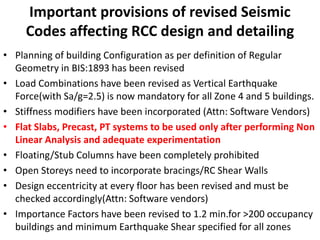
The document summarizes important provisions of revised seismic codes affecting reinforced concrete (RCC) design and detailing, including:
- Revisions to building configuration definitions, load combinations, and stiffness modifiers.
- Prohibitions on certain structural systems without adequate experimentation/analysis.
- Revisions to design eccentricity, foundation isolation, column/beam sizing and reinforcement, and ductility provisions.
- Updates to standards IS:13920 regarding concrete grade, beam-column joints, lap splices, transverse reinforcement, and special confining reinforcement.
- Queries raised regarding compliance of existing/under construction buildings and clarification needed for irregular geometries.

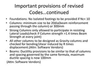


![IS 13920;1993 IS 13920;2016
As per 7.4.8
The area of cross section,
Ash, of the bar forming
rectangular hoop, to be used
as special confining
reinforcement shall not be
less than:
2) In rectangular links:
Ash = 0.18 Sh
fck⁄fy[Ag⁄Ak]
Ash=Max of {0.18 Svh fck⁄fy (Ag⁄Ak-1)
{0.05 Svhfckfy](https://image.slidesharecdn.com/rccdesignanddetailingbasedonrevisedseismiccodes-170630092806/85/Rcc-design-and-detailing-based-on-revised-seismic-codes-23-320.jpg)


![IS13920;2016
8. BEAM
COLUMN
JOINTS OF
MOMENT
RESISITING
FRAMES
Design of Beam
Column Joint for
Distortional
Shear
As per 9.1.1
Shear Strength of Concrete in a joint
NOTE: 1) for joints confined by beams on all four
faces
2) for joints confined by beams on three faces
3) for other joints
Aej, is effective shear area of joint given by bjwj, in
which bj is the effective breadth of joint
perpendicular to the direction of shear force and wj
the effective width of joint bj (see Fig.15) shall be
obtained from following:
Min [bb; bc+0.5hc] if bc<bb
Where
bb=width of beam and bc = width of column
hc= depth of column in considered direction.
τje=1)1.5 Aej √fck
2)1.2 Aej √fck
3)1.0 Aej √fck](https://image.slidesharecdn.com/rccdesignanddetailingbasedonrevisedseismiccodes-170630092806/85/Rcc-design-and-detailing-based-on-revised-seismic-codes-26-320.jpg)