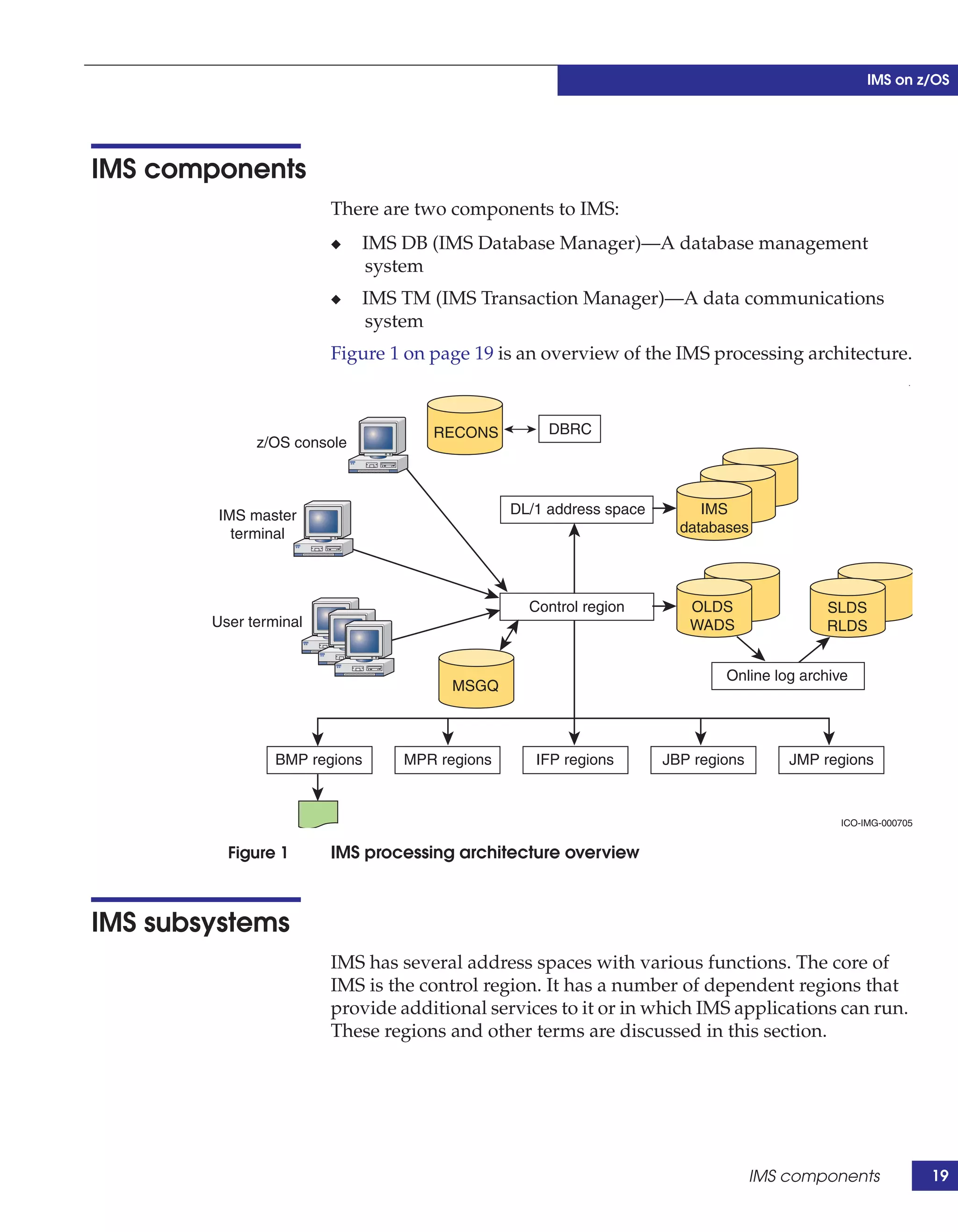
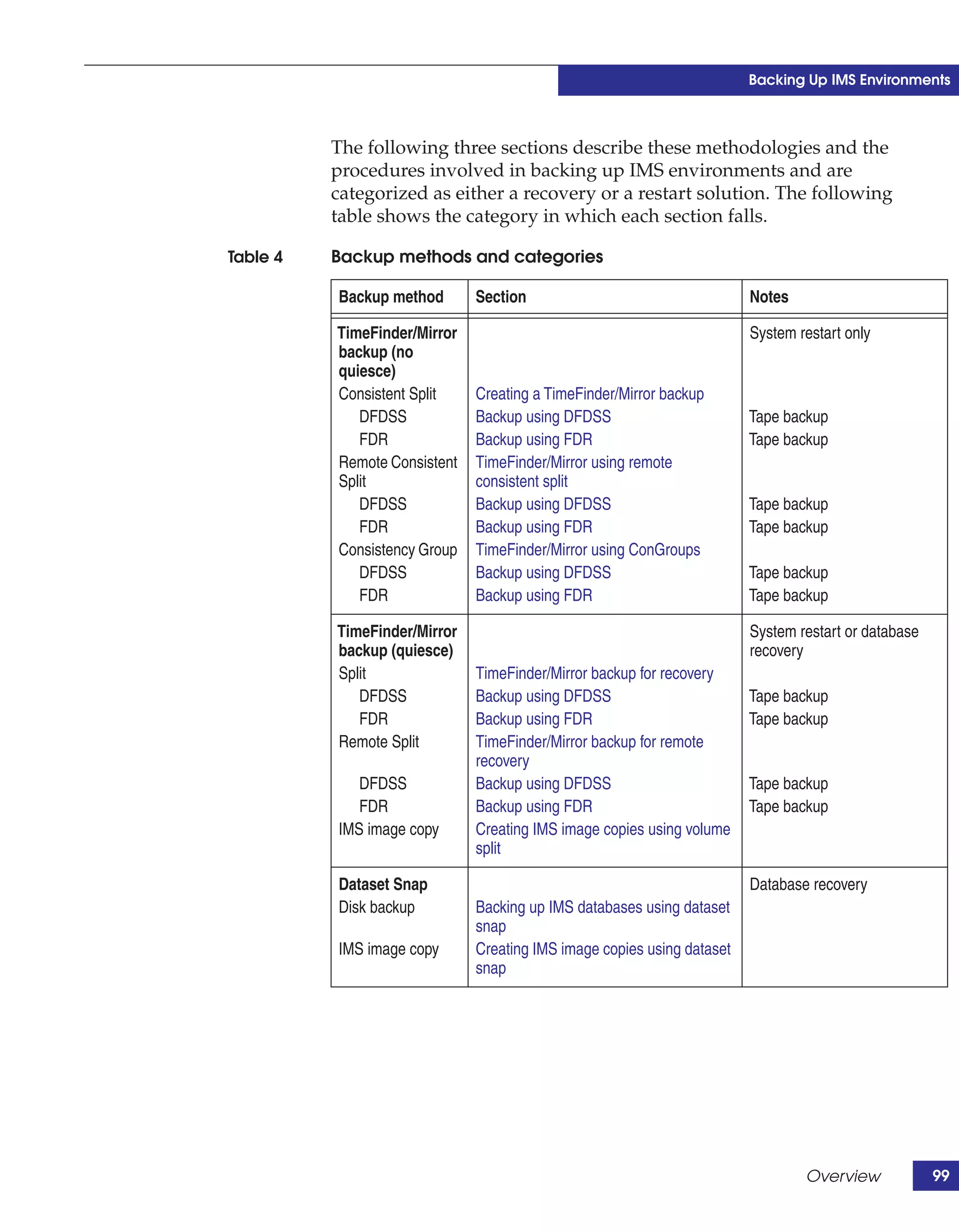
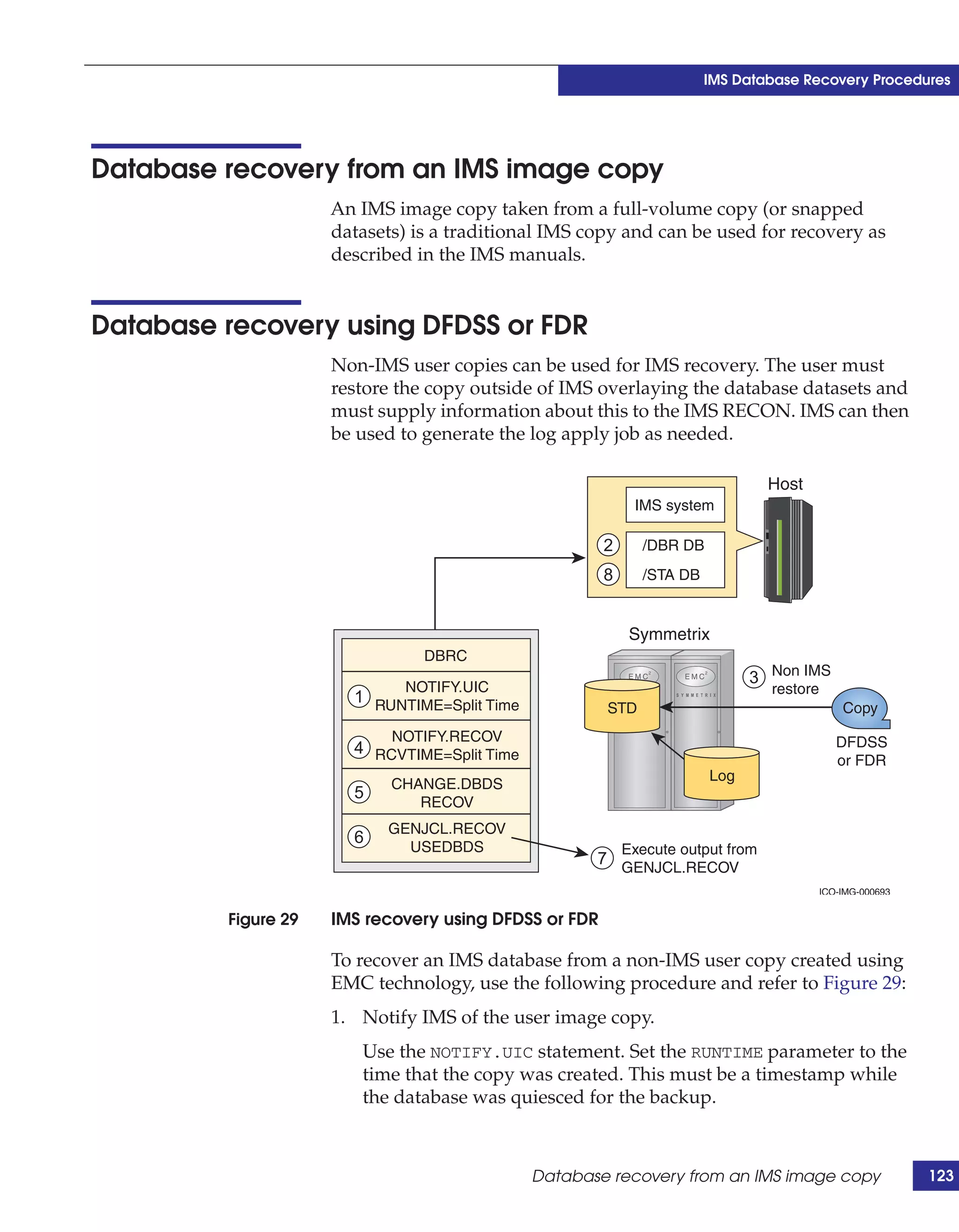
This document provides guidance on using EMC storage solutions with IMS databases on z/OS, describing IMS components, EMC foundation products like Symmetrix and TimeFinder, advanced storage provisioning techniques, cloning IMS databases, backing up and recovering IMS environments, disaster recovery planning, and performance optimization. It is intended to help database and storage administrators understand how to leverage EMC technologies to enhance the performance, availability, and management of IMS databases on the mainframe.
![Preface
Typographical EMC uses the following type style conventions in this document:
conventions
Normal Used in running (nonprocedural) text for:
• Names of interface elements (such as names of windows, dialog boxes, buttons,
fields, and menus)
• Names of resources, attributes, pools, Boolean expressions, buttons, DQL
statements, keywords, clauses, environment variables, functions, utilities
• URLs, pathnames, filenames, directory names, computer names, filenames,
links, groups, service keys, file systems, notifications
Bold Used in running (nonprocedural) text for:
• Names of commands, daemons, options, programs, processes, services,
applications, utilities, kernels, notifications, system calls, man pages
Used in procedures for:
• Names of interface elements (such as names of windows, dialog boxes, buttons,
fields, and menus)
• What user specifically selects, clicks, presses, or types
Italic Used in all text (including procedures) for:
• Full titles of publications referenced in text
• Emphasis (for example a new term)
• Variables
Courier Used for:
• System output, such as an error message or script
• URLs, complete paths, filenames, prompts, and syntax when shown outside of
running text
Courier bold Used for:
• Specific user input (such as commands)
Courier italic Used in procedures for:
• Variables on command line
• User input variables
<> Angle brackets enclose parameter or variable values supplied by the user
[] Square brackets enclose optional values
| Vertical bar indicates alternate selections - the bar means “or”
{} Braces indicate content that you must specify (that is, x or y or z)
... Ellipses indicate nonessential information omitted from the example
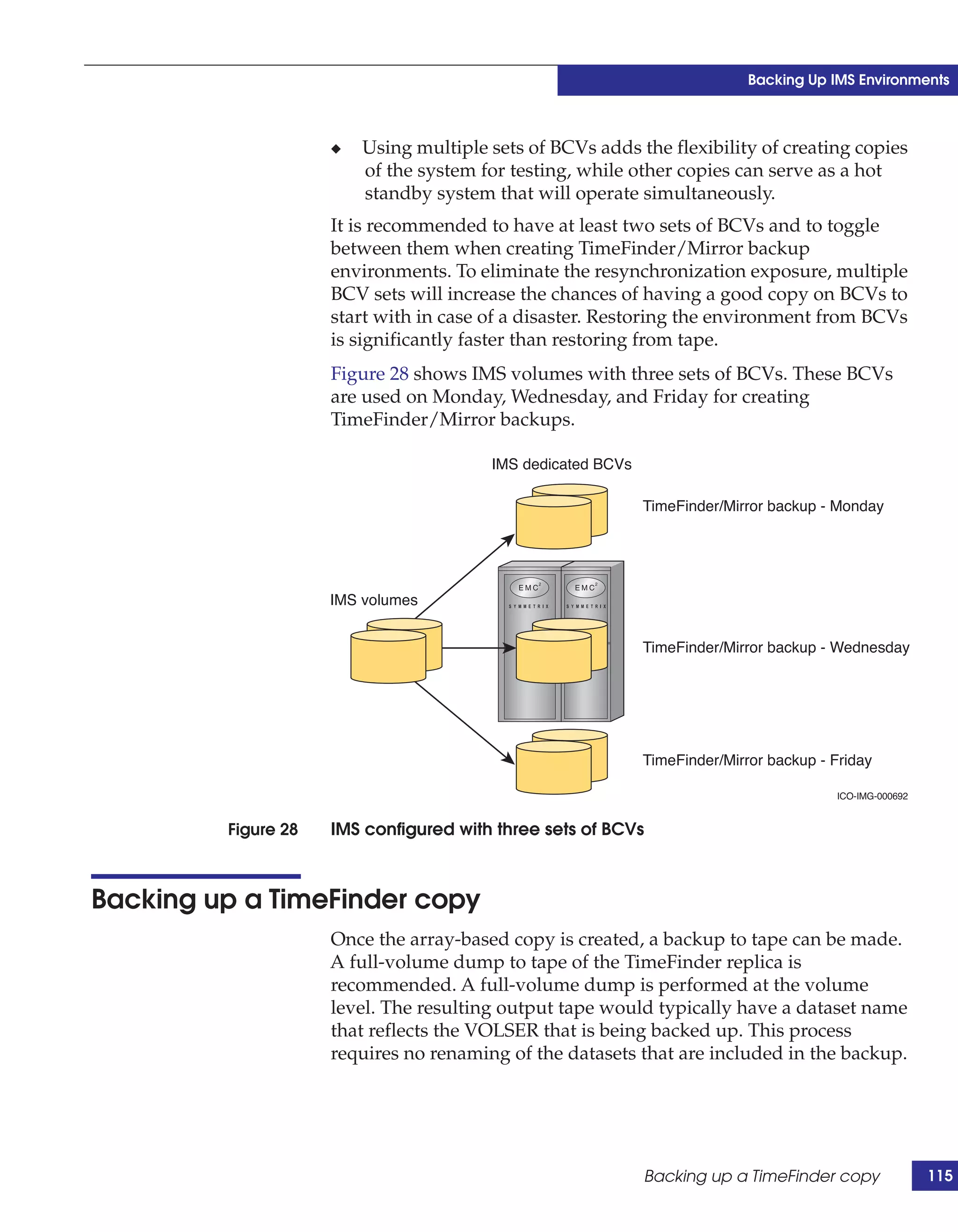
IMS on z/OS Using EMC Symmetrix Storage Systems Version 2.0 15](https://image.slidesharecdn.com/h903-ims-os390zos-symmstoragesystemsldv-130303054052-phpapp01/75/TechBook-IMS-on-z-OS-Using-EMC-Symmetrix-Storage-Systems-15-2048.jpg)


![Coded Agents – with UiPath SDK + LangGraph [Virtual Hands-on Workshop]](https://cdn.slidesharecdn.com/ss_thumbnails/codedagentsdeck-251215155422-5497c599-thumbnail.jpg?width=640&height=640&fit=bounds)


