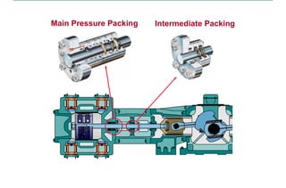
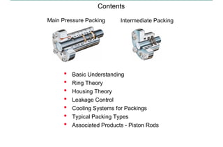
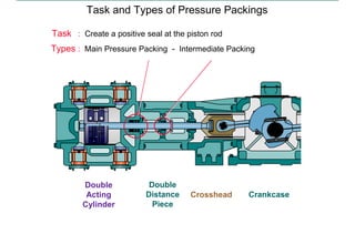
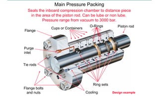
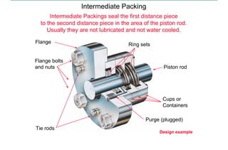
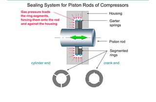
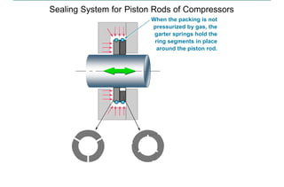
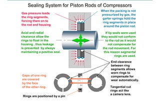
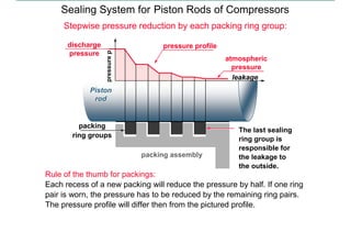
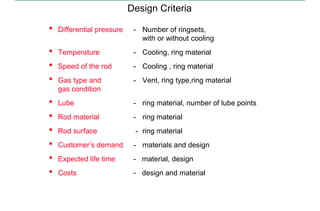
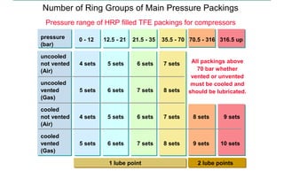
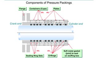
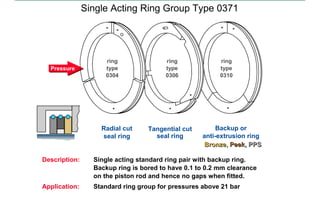
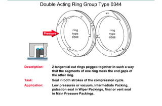
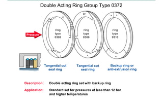
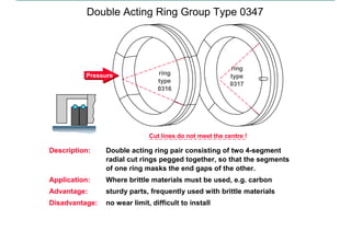
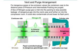
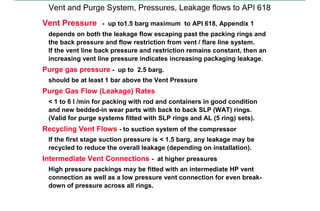
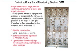
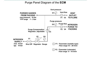
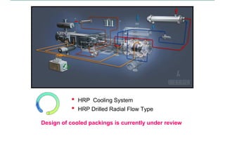
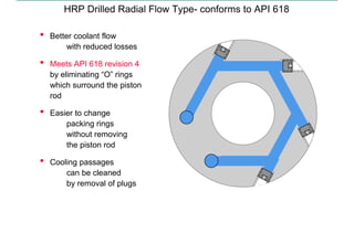
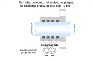
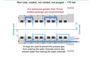
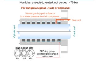
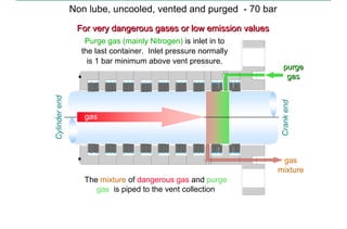
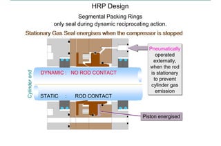
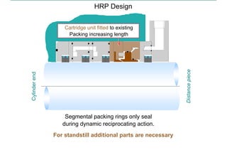
SlideShare a Scribd company logo
1 of 66
Download to read offline
Main Pressure Packing Intermediate Packing
PRESSURE PACKINGS FOR PISTON COMPRESSORS
Contents
• Basic Understanding
• Ring Theory
• Housing Theory
• Leakage Control
• Cooling Systems for Packings
• Typical Packing Types
• Associated Products - Piston Rods
Main Pressure Packing Intermediate Packing
PRESSURE PACKINGS
Basic Understanding
• Task and Types
• Function
• Sealing System
• Design
PRESSURE PACKINGS
Task and Types of Pressure Packings
Task : Create a positive seal at the piston rod
Types : Main Pressure Packing - Intermediate Packing
Double
Distance
Piece
Double
Acting
Cylinder
Crosshead Crankcase
BASIC UNDERSTANDING
Seals the inboard compression chamber to distance piece
in the area of the piston rod. Can be lube or non lube.
Pressure range from vacuum to 3000 bar.
Main Pressure Packing
Ring sets
O-Rings
Flange
Cups or Containers
Tie rods
Purge
inlet
Cooling Design example
Flange bolts
and nuts
Piston rod
BASIC UNDERSTANDING
Intermediate Packings seal the first distance piece
to the second distance piece in the area of the piston rod.
Usually they are not lubricated and not water cooled.
Intermediate Packing
Flange
Cups or
Containers
Ring sets
Tie rods
Purge (plugged)
Flange bolts
and nuts
Design example
Piston rod
BASIC UNDERSTANDING
• Seal gas or oil
– in compression chamber
– in intermediate piece
• Maintain a positive seal
at the piston rod even though there is
lateral movement of the rod
e
n
d
c
l
e
a
r
a
n
c
e
Function of Pressure Packings
axial clearance
piston rod
piston rod
radial
clearance
lateral
axial
BASIC UNDERSTANDING
• The rings segments are held together by garter springs until
the gas pressure is such that they are forced on to the rod
to create the seal.
• Sealing rings are pegged together so that the gaps between
the ring segments of one ring are covered by the ring segments
of the other to reduce leakage.
• Rings can float axially and radially in the grooves of the cups
to compensate for rod movement.
Function of Pressure Packings
piston rod
garter springs
seal rings
BASIC UNDERSTANDING
Sealing System for Piston Rods of Compressors
Segmented
rings
Housing
Piston rod
Garter springs
Radial cut ring Tangential
cut ring
BASIC UNDERSTANDING
Sealing System for Piston Rods of Compressors
Segmented
rings
Housing
Piston rod
Garter
springs
Gas pressure loads
the ring segments,
forcing them onto the rod
and against the housing
crank end
cylinder end
BASIC UNDERSTANDING
Sealing System for Piston Rods of Compressors
When the packing is not
pressurized by gas, the
garter springs hold the
ring segments in place
around the piston rod.
BASIC UNDERSTANDING
Axial and radial
clearance allow the
rings to float in the
housing , thus leakage
is prevented by always
maintaining a positive seal.
Sealing System for Piston Rods of Compressors
If lip seals were used
they would not conform
to the rod as it would
not compensate for
the rod movement. For
this reason segmental
rings are used.
BASIC UNDERSTANDING
Gaps of one ring
are covered
by the face
of the other ring.
Rings are positioned by a pin
Sealing System for Piston Rods of Compressors
BASIC UNDERSTANDING
Sealing System for Piston Rods of Compressors
End clearance
between ring
segments allows
worn rings to
compensate for
wear automatically.
Tangential cut
rings act like
a camera lens.
BASIC UNDERSTANDING
Gaps of one ring
are covered
by the face
of the other ring.
Rings are positioned by a pin
Axial and radial
clearance allow the
rings to float in the
housing , thus leakage
is prevented by always
maintaining a positive seal.
When the packing is not
pressurized by gas, the
garter springs hold the
ring segments in place
around the piston rod.
Gas pressure loads
the ring segments,
forcing them on to
the rod and housing
Sealing System for Piston Rods of Compressors
If lip seals were used
they would not conform
to the rod as it would
not compensate for
the rod movement. For
this reason segmental
rings are used.
End clearance
between ring
segments allows
worn rings to
compensate for
wear automatically.
Tangential cut
rings act like
a camera lens.
BASIC UNDERSTANDING
Sealing System for Piston Rods of Compressors
Stepwise pressure reduction by each packing ring group:
Rule of the thumb for packings:
Each recess of a new packing will reduce the pressure by half. If one ring
pair is worn, the pressure has to be reduced by the remaining ring pairs.
The pressure profile will differ then from the pictured profile.
The last sealing
ring group is
responsible for
the leakage to
the outside.
packing
ring groups
atmospheric
pressure
pressure
p
packing assembly
Piston
rod
Piston
rod
leakage
discharge
pressure
pressure profile
BASIC UNDERSTANDING
Design Criteria
• Differential pressure - Number of ringsets,
with or without cooling
• Temperature - Cooling, ring material
• Speed of the rod - Cooling , ring material
• Gas type and - Vent, ring type,ring material
gas condition
• Lube - ring material, number of lube points
• Rod material - ring material
• Rod surface - ring material
• Customer’s demand - materials and design
• Expected life time - material, design
• Costs - design and material
BASIC UNDERSTANDING
Number of Ring Groups of Main Pressure Packings
Pressure range of HRP filled TFE packings for compressors
pressure
(bar)
uncooled
not vented 4 sets 5 sets 6 sets 7 sets
(Air)
uncooled
vented 5 sets 6 sets 7 sets 8 sets
(Gas)
cooled
not vented 4 sets 5 sets 6 sets 7 sets 8 sets 9 sets
(Air)
cooled
vented 5 sets 6 sets 7 sets 8 sets 9 sets 10 sets
(Gas)
All packings above
70 bar whether
vented or unvented
must be cooled and
should be lubricated.
0 - 12 12.5 - 21 21.5 - 35 35.5 - 70 70.5 - 316 316.5 up
1 lube point 2 lube points
BASIC UNDERSTANDING
Components of Pressure Packings
Flange
Flange Plates
Plates
Soft metal gasket
(joint) to seal
on stuffing box
Soft metal gasket
(joint) to seal
on stuffing box
Sealing Ring Sets
Sealing Ring Sets
Containers (Cups)
Containers (Cups)
etc.
etc. etc.
O-Rings
O-Rings
etc.
Crank end Cylinder end
BASIC UNDERSTANDING
Contents
• Function
• Single Acting Ring Groups
• Double Acting Ring Groups
• Side Loaded Ring Groups
• Special Rings
• Pressure Breakers
• Clearance figures
RING THEORY
Function
Classification of rings according to their functions:
• Seal ring
• Pressure breaker
– reduces the pressure by throttling the gas flow
• Anti-extrusion ring - usually called “backup ring”
– for pressures higher than approx. 15 bar
– made out of stronger material than the seal rings
– located on low pressure side, with a gap between the ring and
the rod smaller than the gap between the housing and the rod
• Ring set: consists of several rings
RING THEORY
Function of a Single Acting Ring Pair
Side clearance in the cups
and radial cut ring gaps
avoid gas traps.
They allow the gas inside
the cups to return
to the cylinder.
Gas enters the cup via the
side clearance in the cups
and gaps in radial cut ring
and loads tangent cut ring
onto piston rod.
Tangent cut ring
gaps are sealed
by radial cut ring
Cylinder end Crank end
Axial movement
of piston rod
Axial movement
of piston rod
Axial movement
of piston rod
Axial movement
of piston rod
tangential ring
radial ring
RING THEORY
Single Acting Ring Group Type 0342
Description: Rings located relative to each by a peg in tangential cut
ring mating hole in radial cut ring. By this gaps of
tangential cut rings are covered by radial cut ring.
Task: Seals only, when the crank end of the cylinder is
compressing gas
Application: Standard ring set for low to medium pressures
Wear limit:
Gaps decrease
to zero when
ring wears.
Rings
without gap
are worn out
and must be
exchanged.
Tangential cut ring
Radial cut ring
Pressure
ring
type
0306
ring
type
0304
gap
gap
RING THEORY
Description: Radial cut ring combined with 6 piece design, instead of
3-piece design tangential cut ring.
Task: Tangential cut is continued across the segment creating
“ Bridge Pieces “
Application: for brittle ring materials , for pressures above 150 bar
with metal Bridge Pieces
Single Acting Ring Group Type 0353
Pressure
6-piece tangential cut ring
Radial cut ring
ring
type
0322
ring
type
0304
RING THEORY
Description: Single acting standard ring pair with backup ring.
Backup ring is bored to have 0.1 to 0.2 mm clearance
on the piston rod and hence no gaps when fitted.
Application: Standard ring group for pressures above 21 bar
Backup or
anti-extrusion ring
Radial cut
seal ring
Single Acting Ring Group Type 0371
Pressure
Tangential cut
seal ring
ring
type
0310
ring
type
0304
ring
type
0306
Bronze, Peek, PPS
Bronze, Peek, PPS
RING THEORY
Function of a Double Acting Ring Group
Gaps in both
tangent cut rings
sealed because
rings are pegged
to prevent gaps
aligning.
Gas enters the cup
via side clearance and
loads tangent cut rings
onto piston rod.
Cylinder end Crank end
On reverse stroke gas
is sealed in the same
manner as described
for the crank stroke.
Cylinder end Crank end
Gas is trapped
in the container.
Axial movement
of piston rod
Axial movement
of piston rod
Axial movement
of piston rod
Axial movement
of piston rod
RING THEORY
Description: 2 tangential cut rings pegged together in such a way
that the segments of one ring mask the end gaps of
the other ring.
Task: Seal in both strokes of the compression cycle.
Application: Low pressures or vacuum, Intermediate Packing,
pulsation seal in Wiper Packings, final or vent seal
in Main Pressure Packings.
Double Acting Ring Group Type 0344
ring
type
0306
ring
type
0308
Pressure
RING THEORY
Description: Double acting ring set with backup ring
Application: Standard set for pressures of less than 12 bar
and higher temperatures
Double Acting Ring Group Type 0372
Tangential cut
seal ring
Tangential cut
seal ring
Backup ring or
anti-extrusion ring
Pressure
ring
type
0310
ring
type
0306
ring
type
0308
RING THEORY
Description: Double acting ring pair consisting of two 4-segment
radial cut rings pegged together, so that the segments
of one ring masks the end gaps of the other.
Application: Where brittle materials must be used, e.g. carbon
Advantage: sturdy parts, frequently used with brittle materials
Disadvantage: no wear limit, difficult to install
Double Acting Ring Group Type 0347
Cut lines do not meet the centre !
ring
type
0317
ring
type
0316
Pressure
RING THEORY
Description: always maintains a seal between tangential cut and
container sealing face due to the inclined nature of the
faces of the 2 radial cut rings and garter spring load.
Application: Main Packings at low pressure side near vent and purge,
also in Intermediate (Partition) Packings and
Oil Tight Packings.
Side Loaded Pressure Ring Group Type 0373
Radial cut ring with
chamfered recess
Radial cut ring with
chamfered boss
Tangential cut
ring with peg
Pressure
ring
type
0314
ring
type
0313
ring
type
0312
Pressure
RING THEORY
Description: No direct leakage path beween the segments,
needs no further ring for proper sealing.
Application: Where small containers must be installed.
Disadvantage: No wear restriction; possibility of damage to inboard
feather edges if rod is inserted into assembled packing.
Special Rings Type 0309 and 0328
Single acting
tangential cut ring
without wear restriction
Double acting
tangential cut ring
without wear restriction
ring
type
0309
ring
type
0328
Pressure Pressure
RING THEORY
Single acting ring
with relief slots in the middle of
segments and chamfers on joint
Description: Reduce pressure and throttle gas pressure pulsations
but not to seal.
Application: Pressures greater then 20 bar,
used on their own filling a recess,
or with backup ring when non metallics (PTFE).
Pressure Breaker Rings 0301 and 1302
Double acting
ring
ring
type
1302
ring
type
0301
Pressure Pressure
RING THEORY
Nomenclature of HRP Rings
Ring
radial
thickness
Recess
dia
Container
(cup)
outer
dia Recess
depth
Container (cup)
thickness
Ring
axial width
Dimensions of standard rings
are according to HRP standard TDSM 115
RING THEORY
Pressure and Intermediate Packings
Flanges
Flanges
Containers
Containers
• Flanges, Containers (cups), Plates
Types - Function - Clearance - Surface Quality - Materials
• Other Parts
Tie rods - O-rings - Static Sealing
HOUSING THEORY
Types of Flanges and Containers
Flanges
Flanges
T-Container (cup) L-Container (cup) Plate
• vented
• plain
• cooled
• lube
• vented
• plain
• for purge
Spigotted Flange
HRP Standard
Recessed Flange
cannot be lapped
Containers (cups) Containers (cups)
Containers
Containers
HOUSING THEORY
Functions of Flanges and Containers
Flange : Contains the connections for lube oil,
cooling water, vent and purge.
Containers are fixed with tie rods to flange.
Container : Contains the ring sets and the holes
(cup) for lube oil, cooling water, and vent.
Plate : Contains the holes for vent.
Masks the milled cooling water grooves.
Compensates the thickness reduction
of containers after reconditioning (by
installing a thicker plate).
Dimensions: Dimensions of flanges, containers, plates
are according to HRP standard TDSM 182
HOUSING THEORY
FLANGES
Spigot dia : Spigot dia. as Container (cup) outer diameter
Recess dia : Recess dia = Stuffing box nom. bore +0 to 0.15 mm
As recesses cannot be lapped effectively,
recessed type flanges should be avoided.
SEALING FACES on Containers, Flanges and Plates
Surface finish low pressure: < 70 bar high pressure: > 70 bar
and Flatness : uncooled Packings low MOL weight or
cooled Packings
0.4
& 0.002
0.2
& 0.001
or
Clearance and Surface Quality
DETAILS - HOUSING THEORY
Standard : Grey iron BS1452 GR.250
Carbon steel BS970 GR 070M55
Stainless steel BS970 GR 316S16
Specials : As required by customers
Materials
Refer to TDSM213 for application details via HRP Intranet
DETAILS - HOUSING THEORY
Details: O-Rings - Static Sealing
High material and surface quality
Captive rectangular
section gasket (joint)
from copper or soft iron
O-ring material according to customer’s order
Tie rod
OTHER COMPONENTS
Details: Static Sealing Function
The joint forms the only static seal
as part of the main pressure packing,
which seals against the bottom of
the stuffing box in the compressor.
It is important that the static seal is
flat and parallel.
It is also important that there is a
good surface at the bottom of the
stuffing box with no contamination.
This is as important a seal
as any of the sealing rings.
OTHER COMPONENTS
• Calculation of Leakage Rates by HRP
• Leakage Control System ECM
LEAKAGE
Calculation of Leakage Rates to HRP Standards
It is difficult to define exactly how much gas will leak through a pressure
packing. A slight leakage is fundamental to the operation of the packing.
Major factors influencing leakage are
• the discharge pressure of the compressor,
• the size of the piston rod
• the molecular weight of the gas
• any lubrication.
Secondary factors include surface finish of the rod and the containers,
gas contamination and machine misalignments.
Compressors can suffer higher than normal leakage
• if operated at very low pressures,
• if running at partial or off-load,
• if (new) packings have not bedded in.
LEAKAGE
Vent and Purge Arrangement
For dangerous gases or low emission values the containers near to the
distance piece of Pressure and Intermediate Packing are purged.
A flow of Nitrogen purge gas is inlet into the packing to stop possible
leakage of dangerous gas into the crank case and further on into the
compressor room. It could also contaminate oil and lower its flash point.
Crankcase side Cylinder side
Nitrogen IN
Piped controlled leakage
to dangerous gas/nitrogen vent Lubrication (on top)
Nitrogen
Oil drain
Nitrogen Dangerous
gas
to distance
piece vent
LEAKAGE
Vent and Purge System, Pressures, Leakage flows to API 618
Vent Pressure - up to1.5 barg maximum to API 618, Appendix 1
depends on both the leakage flow escaping past the packing rings and
the back pressure and flow restriction from vent / flare line system.
If the vent line back pressure and restriction remains constant, then an
increasing vent line pressure indicates increasing packaging leakage.
Purge gas pressure - up to 2.5 barg.
should be at least 1 bar above the Vent Pressure
Purge Gas Flow (Leakage) Rates
< 1 to 6 l /min for packing with rod and containers in good condition
and new bedded-in wear parts with back to back SLP (WAT) rings.
(Valid for purge systems fitted with SLP rings and AL (5 ring) sets).
Recycling Vent Flows - to suction system of the compressor
If the first stage suction pressure is < 1.5 barg, any leakage may be
recycled to reduce the overall leakage (depending on installation).
Intermediate Vent Connections - at higher pressures
High pressure packings may be fitted with an intermediate HP vent
connection as well as a low pressure vent connection for even break-
down of pressure across all rings.
LEAKAGE
Purge pressure and purge flow are
controlled, consumption of purge gas
(N2) is minimized.
The equipment adjusts purge gas inlet
pressure to compensate for increase in
vent pressure and keeps the differential
pressure of the purge to vent gas.
If gas flow to flare exceeds a limiting
value an alarm is switched on.
Emission Control and Monitoring System ECM
• Modular construction,
up to 4 cylinders per cabinet
• Satisfies emissions legislation
to API618 & NACE
• Optional flow controlled purge
for valve unloaders, intermediate &
wiper packings
LEAKAGE
F1: Flowmeter (metallic type)
Flow range 10 – 30 l/min
F2: Flowmeter (rotameter)
Flow range 0 – 10 l/min
Purge Panel Diagram of the ECM
Vent pressure
Vent flow
F1
VENT
OUTLET
TO FLARE
NITROGEN
PURGE TO
PACKING
Purge flow
G3
F2 V4
G1
V5
Purge pressure
V3
Purge Compensation
Regulator, adjustable
Gauge
Regulator
Shut Off
NITROGEN
SUPPLY
max. 16 bar
typ. 10 bar
V2
V1
PURGED GASSES
FROM PACKING
max pressure 16 bar
YYP range 1 – 3 bar
G2
LEAKAGE
• HRP Cooling System
• HRP Drilled Radial Flow Type
Design of cooled packings is currently under review
COOLING OF PRESSURE PACKINGS
HRP Cooling System
Frictional heat has to be dissipated.
For discharge pressures greater than 70 bar
water cooling is necessary in general.
For lower pressures water
cooling is necessary
only under special conditions.
COOLING OF PRESSURE PACKINGS
HRP Cooling System
Forced flow cooling by 340° milled groove gives:
– improved water flow
– no stagnancy
– reduced pressure drop through packing cooling system
water
water
outlet
cooling
water
inlet
water
water
outlet
water
inlet
Required cooling water:
pressure : 0.5 to 5 bar
max. temperature: 40°C
COOLING OF PRESSURE PACKINGS
HRP Drilled Radial Flow Type- conforms to API 618
• Better coolant flow
with reduced losses
• Meets API 618 revision 4
by eliminating “O” rings
which surround the piston
rod
• Easier to change
packing rings
without removing
the piston rod
• Cooling passages
can be cleaned
by removal of plugs
COOLING OF PRESSURE PACKINGS
• Main Characteristics
• Typical Pressure Packing Types
• HRP Stationary Gas Seal
• Features of HRP Pressure Packings
• Testing of Pressure Packings
PRESSURE PACKING TYPES
Characteristics
The main characteristics of Pressure Packings are:
• lube or non-lube
• with or without cooling
• with or without vent
• with vent and
• with or without purge
These characteristics are dependent upon:
• discharge pressure
• differential temperature.
• piston speed
• customer specification
• process requirements
Type and number of ring groups depend on the design criteria
• see “Basic Understanding”.
PRESSURE PACKING TYPES
Non lube, uncooled, not vented, not purged,
for discharge pressures less than 10 bar
Double acting ring
groups are used
0308
0306
RING GROUP 0344
Crank
end
Cylinder
end
TYPICAL PACKING TYPES
Non lube, uncooled, not vented, not purged,
RING GROUP 0371
0310
0304 0306
Crank
end
Cylinder
end
for discharge pressures less than 30 bar
Pressure Breaker Ring Single acting ring groups
RING GROUP 0349
0310
1302
TYPICAL PACKING TYPES
Lube
Lube, uncooled, not vented, not purged,
for discharge pressure from 30 bar to 70 bar
Crank
end
Cylinder
end
oil
oil
from cylinder
lube pump
RING GROUP 0371
0310
0304 0306
Pressure Single acting
Breaker Ring ring groups
RING GROUP 0349
0310
1302
TYPICAL PACKING TYPES
Non lube, cooled, not vented, not purged - 170 bar
Crank
end
Cylinder
end
For pressures greater than 70 bar
cooled packings are recommended
O-rings are used to prevent the process gas
from entering the water channels and to also
prevent water from leaving the water channels
TYPICAL PACKING TYPES
Non lube, uncooled, vented, not purged - 70 bar
Vented gas is piped to flare or
to a lower pressure level of compressor.
Gas vent
SLP ring group:
side load pressurized,
behind vent
For dangerous gases - toxic or explosive:
Crank
end
Cylinder
end
RING GROUP 0373
0312
0314 0313
TYPICAL PACKING TYPES
Non lube, uncooled, vented and purged - 70 bar
For very dangerous gases or low emission values
purge
gas
purge
gas
gas
mixture
Crank
end
Cylinder
end
gas
Purge gas (mainly Nitrogen) is inlet in to
the last container. Inlet pressure normally
is 1 bar minimum above vent pressure.
The mixture of dangerous gas and purge
gas is piped to the vent collection
TYPICAL PACKING TYPES
HRP Design
Segmental Packing Rings
only seal during dynamic reciprocating action.
Piston energised
Piston energised
DYNAMIC : NO ROD CONTACT
STATIC : ROD CONTACT
Pneumatically
operated
externally,
when the rod
is stationary
to prevent
cylinder gas
emission
Cylinder
end
Stationary Gas Seal energises when the compressor is stopped
STATIONARY GAS SEAL
Segmental packing rings only seal
during dynamic reciprocating action.
Distance
piece
Cylinder
end HRP Design
Cartridge unit fitted to existing
Packing increasing length
For standstill additional parts are necessary
STATIONARY GAS SEAL
Application Features
TYPICAL WATER COOLED PRESSURE PACKING
Face & outside dia connections
make flange more serviceable.
Thermocouple to detect
increases in temperature
Detachable
flange to aid
assembly
Vent connection can be fitted with
an off-line flow measurement device
Facility for rod
drop indicator
to detect
rider ring
wear
FEATURES OF HRP PRESSURE PACKINGS
Design Features
Spiral wound
Gasket,
optional, to
reduce static
leakage
Tee shaped Cup complete with`SLP' Rings & purge
(API618) allows for sealing faces to be machine-lapped
Milled groove
Coolant Channels
to reduce pressure
drop to a minimum
`O'-Ring design can be captive, totally eliminating
possibility of gas leakage into water channels
Fully lapped faces with O-Rings
eliminate static leakage
TYPICAL WATER COOLED PRESSURE PACKING
FEATURES OF HRP PRESSURE PACKINGS
Standard and Extra Leakage Testing Procedures
Standard test of water cooled packings:
• Pressurised air (6 bar) is connected to cooling water inlet.
• Air inlet valve will be closed.
• Pressure drop is checked at the closed volume
Standard bubble test
• Pressurised air (6 bar) is connected to cooling water inlet.
• Packings are submerged in water, bubbles indicate leakage.
• After test packings are disassembled, cleaned, dried and
reassembled.
• Test do not show reasseambling errors.
Extra test when required - all packings
• Check of the gas tightness between the test flanges
TESTING OF HRP PRESSURE PACKINGS
• Piston Rods
ASSOCIATED PRODUCTS
Piston Rods
Lube air compressor - unhardened 30 HRC, cut threads
Process gas compr. - Induction hardened (occasionally nitrided)
50 to 55 HRC, rolled threads
Coated rods - Thermal plasma sprayed,
mostly to 65 - 70 HRC
Materials
Materials
Surface Finish - hardened rods Ra : 0,2 - 0,4 µ
µ
µ
µm
- coated rods Ra : 0,2 - 0,25 µ
µ
µ
µm
Coating - Chromium oxide
for reducing - Ceramics (Metco P130), produced
rod wear and/or with plasma gun method (HVOF)
reconditioning - Tungsten Carbide produced with plasma
gun (HVOF) or “Detonation Gun” method
Surface Finish
Surface Finish - hardened rods Ra : 0,2 - 0,4 µ
µ
µ
µm
- coated rods Ra : 0,2 - 0,25 µ
µ
µ
µm
Coating - Chromium oxide
for reducing - Ceramics (Metco P130), produced
rod wear and/or with plasma gun method (HVOF)
reconditioning - Tungsten Carbide produced with plasma
gun (HVOF) or “Detonation Gun” method
higher value of Ra
preferred
ASSOCIATED PRODUCTS
End
of the Training File
Pressure Packings
END

More Related Content

Similar to 202999415-1-Pressure-Packing for compressor

Halderman ch033 lecture
Halderman ch033 lectureHalderman ch033 lecture
Halderman ch033 lecture
mcfalltj
 
Chapter 28
Chapter 28Chapter 28
Chapter 28
mcfalltj
 
03 engine bottom end
03 engine bottom end03 engine bottom end
03 engine bottom end
Emmanuel Kolo
 
Parts bearings gearing
Parts  bearings  gearingParts  bearings  gearing
Parts bearings gearing
Rebel Munna
 

Similar to 202999415-1-Pressure-Packing for compressor (20)

Piston presentation
Piston presentationPiston presentation
Piston presentation
 
MECHANICAL PISTON ROD PACKING
MECHANICAL PISTON ROD PACKINGMECHANICAL PISTON ROD PACKING
MECHANICAL PISTON ROD PACKING
 
Introduction of engine components
Introduction of engine componentsIntroduction of engine components
Introduction of engine components
 
8. Reciprocating compressors.pdf
8. Reciprocating compressors.pdf8. Reciprocating compressors.pdf
8. Reciprocating compressors.pdf
 
Halderman ch033 lecture
Halderman ch033 lectureHalderman ch033 lecture
Halderman ch033 lecture
 
Fundamentals of mechanical seals
Fundamentals of mechanical sealsFundamentals of mechanical seals
Fundamentals of mechanical seals
 
Chapter 28
Chapter 28Chapter 28
Chapter 28
 
Recipteng3
Recipteng3Recipteng3
Recipteng3
 
Reciptengcomp3
Reciptengcomp3Reciptengcomp3
Reciptengcomp3
 
Floating Ball Valve, Floating Ball Valve Manufacturers - WOM Group
Floating Ball Valve, Floating Ball Valve Manufacturers - WOM GroupFloating Ball Valve, Floating Ball Valve Manufacturers - WOM Group
Floating Ball Valve, Floating Ball Valve Manufacturers - WOM Group
 
Valves Materials - part 2
Valves Materials - part 2Valves Materials - part 2
Valves Materials - part 2
 
Pistons
PistonsPistons
Pistons
 
Piston
PistonPiston
Piston
 
ENGINE COMPONENT-Pistons
ENGINE COMPONENT-PistonsENGINE COMPONENT-Pistons
ENGINE COMPONENT-Pistons
 
Floating Ball Valve, Floating Ball Valve Surface Equipment - WOM Group
Floating Ball Valve, Floating Ball Valve Surface Equipment - WOM GroupFloating Ball Valve, Floating Ball Valve Surface Equipment - WOM Group
Floating Ball Valve, Floating Ball Valve Surface Equipment - WOM Group
 
Floating Ball Valve, Floating Ball Valve Oilfield Equipment- WOM Group
Floating Ball Valve, Floating Ball Valve Oilfield Equipment- WOM GroupFloating Ball Valve, Floating Ball Valve Oilfield Equipment- WOM Group
Floating Ball Valve, Floating Ball Valve Oilfield Equipment- WOM Group
 
Mechanical Seal for Pumps by Engr. Muhammad Shahbaz
Mechanical Seal for Pumps by Engr. Muhammad ShahbazMechanical Seal for Pumps by Engr. Muhammad Shahbaz
Mechanical Seal for Pumps by Engr. Muhammad Shahbaz
 
03 engine bottom end
03 engine bottom end03 engine bottom end
03 engine bottom end
 
Parts bearings gearing
Parts  bearings  gearingParts  bearings  gearing
Parts bearings gearing
 
Lakhan singh
Lakhan singhLakhan singh
Lakhan singh
 

Recently uploaded

IAC 2024 - IA Fast Track to Search Focused AI Solutions
IAC 2024 - IA Fast Track to Search Focused AI SolutionsIAC 2024 - IA Fast Track to Search Focused AI Solutions
IAC 2024 - IA Fast Track to Search Focused AI Solutions
Enterprise Knowledge
 

Recently uploaded (20)

How to Troubleshoot Apps for the Modern Connected Worker
How to Troubleshoot Apps for the Modern Connected WorkerHow to Troubleshoot Apps for the Modern Connected Worker
How to Troubleshoot Apps for the Modern Connected Worker
 
From Event to Action: Accelerate Your Decision Making with Real-Time Automation
From Event to Action: Accelerate Your Decision Making with Real-Time AutomationFrom Event to Action: Accelerate Your Decision Making with Real-Time Automation
From Event to Action: Accelerate Your Decision Making with Real-Time Automation
 
04-2024-HHUG-Sales-and-Marketing-Alignment.pptx
04-2024-HHUG-Sales-and-Marketing-Alignment.pptx04-2024-HHUG-Sales-and-Marketing-Alignment.pptx
04-2024-HHUG-Sales-and-Marketing-Alignment.pptx
 
Workshop - Best of Both Worlds_ Combine KG and Vector search for enhanced R...
Workshop - Best of Both Worlds_ Combine  KG and Vector search for  enhanced R...Workshop - Best of Both Worlds_ Combine  KG and Vector search for  enhanced R...
Workshop - Best of Both Worlds_ Combine KG and Vector search for enhanced R...
 
ProductAnonymous-April2024-WinProductDiscovery-MelissaKlemke
ProductAnonymous-April2024-WinProductDiscovery-MelissaKlemkeProductAnonymous-April2024-WinProductDiscovery-MelissaKlemke
ProductAnonymous-April2024-WinProductDiscovery-MelissaKlemke
 
08448380779 Call Girls In Diplomatic Enclave Women Seeking Men
08448380779 Call Girls In Diplomatic Enclave Women Seeking Men08448380779 Call Girls In Diplomatic Enclave Women Seeking Men
08448380779 Call Girls In Diplomatic Enclave Women Seeking Men
 
Strategies for Landing an Oracle DBA Job as a Fresher
Strategies for Landing an Oracle DBA Job as a FresherStrategies for Landing an Oracle DBA Job as a Fresher
Strategies for Landing an Oracle DBA Job as a Fresher
 
presentation ICT roal in 21st century education
presentation ICT roal in 21st century educationpresentation ICT roal in 21st century education
presentation ICT roal in 21st century education
 
Raspberry Pi 5: Challenges and Solutions in Bringing up an OpenGL/Vulkan Driv...
Raspberry Pi 5: Challenges and Solutions in Bringing up an OpenGL/Vulkan Driv...Raspberry Pi 5: Challenges and Solutions in Bringing up an OpenGL/Vulkan Driv...
Raspberry Pi 5: Challenges and Solutions in Bringing up an OpenGL/Vulkan Driv...
 
Presentation on how to chat with PDF using ChatGPT code interpreter
Presentation on how to chat with PDF using ChatGPT code interpreterPresentation on how to chat with PDF using ChatGPT code interpreter
Presentation on how to chat with PDF using ChatGPT code interpreter
 
08448380779 Call Girls In Friends Colony Women Seeking Men
08448380779 Call Girls In Friends Colony Women Seeking Men08448380779 Call Girls In Friends Colony Women Seeking Men
08448380779 Call Girls In Friends Colony Women Seeking Men
 
Tech Trends Report 2024 Future Today Institute.pdf
Tech Trends Report 2024 Future Today Institute.pdfTech Trends Report 2024 Future Today Institute.pdf
Tech Trends Report 2024 Future Today Institute.pdf
 
Scaling API-first – The story of a global engineering organization
Scaling API-first – The story of a global engineering organizationScaling API-first – The story of a global engineering organization
Scaling API-first – The story of a global engineering organization
 
Strategies for Unlocking Knowledge Management in Microsoft 365 in the Copilot...
Strategies for Unlocking Knowledge Management in Microsoft 365 in the Copilot...Strategies for Unlocking Knowledge Management in Microsoft 365 in the Copilot...
Strategies for Unlocking Knowledge Management in Microsoft 365 in the Copilot...
 
The Role of Taxonomy and Ontology in Semantic Layers - Heather Hedden.pdf
The Role of Taxonomy and Ontology in Semantic Layers - Heather Hedden.pdfThe Role of Taxonomy and Ontology in Semantic Layers - Heather Hedden.pdf
The Role of Taxonomy and Ontology in Semantic Layers - Heather Hedden.pdf
 
IAC 2024 - IA Fast Track to Search Focused AI Solutions
IAC 2024 - IA Fast Track to Search Focused AI SolutionsIAC 2024 - IA Fast Track to Search Focused AI Solutions
IAC 2024 - IA Fast Track to Search Focused AI Solutions
 
[2024]Digital Global Overview Report 2024 Meltwater.pdf
[2024]Digital Global Overview Report 2024 Meltwater.pdf[2024]Digital Global Overview Report 2024 Meltwater.pdf
[2024]Digital Global Overview Report 2024 Meltwater.pdf
 
Boost PC performance: How more available memory can improve productivity
Boost PC performance: How more available memory can improve productivityBoost PC performance: How more available memory can improve productivity
Boost PC performance: How more available memory can improve productivity
 
Apidays Singapore 2024 - Building Digital Trust in a Digital Economy by Veron...
Apidays Singapore 2024 - Building Digital Trust in a Digital Economy by Veron...Apidays Singapore 2024 - Building Digital Trust in a Digital Economy by Veron...
Apidays Singapore 2024 - Building Digital Trust in a Digital Economy by Veron...
 
Partners Life - Insurer Innovation Award 2024
Partners Life - Insurer Innovation Award 2024Partners Life - Insurer Innovation Award 2024
Partners Life - Insurer Innovation Award 2024
 

202999415-1-Pressure-Packing for compressor

  • 1. Main Pressure Packing Intermediate Packing PRESSURE PACKINGS FOR PISTON COMPRESSORS
  • 2. Contents • Basic Understanding • Ring Theory • Housing Theory • Leakage Control • Cooling Systems for Packings • Typical Packing Types • Associated Products - Piston Rods Main Pressure Packing Intermediate Packing PRESSURE PACKINGS
  • 3. Basic Understanding • Task and Types • Function • Sealing System • Design PRESSURE PACKINGS
  • 4. Task and Types of Pressure Packings Task : Create a positive seal at the piston rod Types : Main Pressure Packing - Intermediate Packing Double Distance Piece Double Acting Cylinder Crosshead Crankcase BASIC UNDERSTANDING
  • 5. Seals the inboard compression chamber to distance piece in the area of the piston rod. Can be lube or non lube. Pressure range from vacuum to 3000 bar. Main Pressure Packing Ring sets O-Rings Flange Cups or Containers Tie rods Purge inlet Cooling Design example Flange bolts and nuts Piston rod BASIC UNDERSTANDING
  • 6. Intermediate Packings seal the first distance piece to the second distance piece in the area of the piston rod. Usually they are not lubricated and not water cooled. Intermediate Packing Flange Cups or Containers Ring sets Tie rods Purge (plugged) Flange bolts and nuts Design example Piston rod BASIC UNDERSTANDING
  • 7. • Seal gas or oil – in compression chamber – in intermediate piece • Maintain a positive seal at the piston rod even though there is lateral movement of the rod e n d c l e a r a n c e Function of Pressure Packings axial clearance piston rod piston rod radial clearance lateral axial BASIC UNDERSTANDING
  • 8. • The rings segments are held together by garter springs until the gas pressure is such that they are forced on to the rod to create the seal. • Sealing rings are pegged together so that the gaps between the ring segments of one ring are covered by the ring segments of the other to reduce leakage. • Rings can float axially and radially in the grooves of the cups to compensate for rod movement. Function of Pressure Packings piston rod garter springs seal rings BASIC UNDERSTANDING
  • 9. Sealing System for Piston Rods of Compressors Segmented rings Housing Piston rod Garter springs Radial cut ring Tangential cut ring BASIC UNDERSTANDING
  • 10. Sealing System for Piston Rods of Compressors Segmented rings Housing Piston rod Garter springs Gas pressure loads the ring segments, forcing them onto the rod and against the housing crank end cylinder end BASIC UNDERSTANDING
  • 11. Sealing System for Piston Rods of Compressors When the packing is not pressurized by gas, the garter springs hold the ring segments in place around the piston rod. BASIC UNDERSTANDING
  • 12. Axial and radial clearance allow the rings to float in the housing , thus leakage is prevented by always maintaining a positive seal. Sealing System for Piston Rods of Compressors If lip seals were used they would not conform to the rod as it would not compensate for the rod movement. For this reason segmental rings are used. BASIC UNDERSTANDING
  • 13. Gaps of one ring are covered by the face of the other ring. Rings are positioned by a pin Sealing System for Piston Rods of Compressors BASIC UNDERSTANDING
  • 14. Sealing System for Piston Rods of Compressors End clearance between ring segments allows worn rings to compensate for wear automatically. Tangential cut rings act like a camera lens. BASIC UNDERSTANDING
  • 15. Gaps of one ring are covered by the face of the other ring. Rings are positioned by a pin Axial and radial clearance allow the rings to float in the housing , thus leakage is prevented by always maintaining a positive seal. When the packing is not pressurized by gas, the garter springs hold the ring segments in place around the piston rod. Gas pressure loads the ring segments, forcing them on to the rod and housing Sealing System for Piston Rods of Compressors If lip seals were used they would not conform to the rod as it would not compensate for the rod movement. For this reason segmental rings are used. End clearance between ring segments allows worn rings to compensate for wear automatically. Tangential cut rings act like a camera lens. BASIC UNDERSTANDING
  • 16. Sealing System for Piston Rods of Compressors Stepwise pressure reduction by each packing ring group: Rule of the thumb for packings: Each recess of a new packing will reduce the pressure by half. If one ring pair is worn, the pressure has to be reduced by the remaining ring pairs. The pressure profile will differ then from the pictured profile. The last sealing ring group is responsible for the leakage to the outside. packing ring groups atmospheric pressure pressure p packing assembly Piston rod Piston rod leakage discharge pressure pressure profile BASIC UNDERSTANDING
  • 17. Design Criteria • Differential pressure - Number of ringsets, with or without cooling • Temperature - Cooling, ring material • Speed of the rod - Cooling , ring material • Gas type and - Vent, ring type,ring material gas condition • Lube - ring material, number of lube points • Rod material - ring material • Rod surface - ring material • Customer’s demand - materials and design • Expected life time - material, design • Costs - design and material BASIC UNDERSTANDING
  • 18. Number of Ring Groups of Main Pressure Packings Pressure range of HRP filled TFE packings for compressors pressure (bar) uncooled not vented 4 sets 5 sets 6 sets 7 sets (Air) uncooled vented 5 sets 6 sets 7 sets 8 sets (Gas) cooled not vented 4 sets 5 sets 6 sets 7 sets 8 sets 9 sets (Air) cooled vented 5 sets 6 sets 7 sets 8 sets 9 sets 10 sets (Gas) All packings above 70 bar whether vented or unvented must be cooled and should be lubricated. 0 - 12 12.5 - 21 21.5 - 35 35.5 - 70 70.5 - 316 316.5 up 1 lube point 2 lube points BASIC UNDERSTANDING
  • 19. Components of Pressure Packings Flange Flange Plates Plates Soft metal gasket (joint) to seal on stuffing box Soft metal gasket (joint) to seal on stuffing box Sealing Ring Sets Sealing Ring Sets Containers (Cups) Containers (Cups) etc. etc. etc. O-Rings O-Rings etc. Crank end Cylinder end BASIC UNDERSTANDING
  • 20. Contents • Function • Single Acting Ring Groups • Double Acting Ring Groups • Side Loaded Ring Groups • Special Rings • Pressure Breakers • Clearance figures RING THEORY
  • 21. Function Classification of rings according to their functions: • Seal ring • Pressure breaker – reduces the pressure by throttling the gas flow • Anti-extrusion ring - usually called “backup ring” – for pressures higher than approx. 15 bar – made out of stronger material than the seal rings – located on low pressure side, with a gap between the ring and the rod smaller than the gap between the housing and the rod • Ring set: consists of several rings RING THEORY
  • 22. Function of a Single Acting Ring Pair Side clearance in the cups and radial cut ring gaps avoid gas traps. They allow the gas inside the cups to return to the cylinder. Gas enters the cup via the side clearance in the cups and gaps in radial cut ring and loads tangent cut ring onto piston rod. Tangent cut ring gaps are sealed by radial cut ring Cylinder end Crank end Cylinder end Crank end Axial movement of piston rod Axial movement of piston rod Axial movement of piston rod Axial movement of piston rod tangential ring radial ring RING THEORY
  • 23. Single Acting Ring Group Type 0342 Description: Rings located relative to each by a peg in tangential cut ring mating hole in radial cut ring. By this gaps of tangential cut rings are covered by radial cut ring. Task: Seals only, when the crank end of the cylinder is compressing gas Application: Standard ring set for low to medium pressures Wear limit: Gaps decrease to zero when ring wears. Rings without gap are worn out and must be exchanged. Tangential cut ring Radial cut ring Pressure ring type 0306 ring type 0304 gap gap RING THEORY
  • 24. Description: Radial cut ring combined with 6 piece design, instead of 3-piece design tangential cut ring. Task: Tangential cut is continued across the segment creating “ Bridge Pieces “ Application: for brittle ring materials , for pressures above 150 bar with metal Bridge Pieces Single Acting Ring Group Type 0353 Pressure 6-piece tangential cut ring Radial cut ring ring type 0322 ring type 0304 RING THEORY
  • 25. Description: Single acting standard ring pair with backup ring. Backup ring is bored to have 0.1 to 0.2 mm clearance on the piston rod and hence no gaps when fitted. Application: Standard ring group for pressures above 21 bar Backup or anti-extrusion ring Radial cut seal ring Single Acting Ring Group Type 0371 Pressure Tangential cut seal ring ring type 0310 ring type 0304 ring type 0306 Bronze, Peek, PPS Bronze, Peek, PPS RING THEORY
  • 26. Function of a Double Acting Ring Group Gaps in both tangent cut rings sealed because rings are pegged to prevent gaps aligning. Gas enters the cup via side clearance and loads tangent cut rings onto piston rod. Cylinder end Crank end On reverse stroke gas is sealed in the same manner as described for the crank stroke. Cylinder end Crank end Gas is trapped in the container. Axial movement of piston rod Axial movement of piston rod Axial movement of piston rod Axial movement of piston rod RING THEORY
  • 27. Description: 2 tangential cut rings pegged together in such a way that the segments of one ring mask the end gaps of the other ring. Task: Seal in both strokes of the compression cycle. Application: Low pressures or vacuum, Intermediate Packing, pulsation seal in Wiper Packings, final or vent seal in Main Pressure Packings. Double Acting Ring Group Type 0344 ring type 0306 ring type 0308 Pressure RING THEORY
  • 28. Description: Double acting ring set with backup ring Application: Standard set for pressures of less than 12 bar and higher temperatures Double Acting Ring Group Type 0372 Tangential cut seal ring Tangential cut seal ring Backup ring or anti-extrusion ring Pressure ring type 0310 ring type 0306 ring type 0308 RING THEORY
  • 29. Description: Double acting ring pair consisting of two 4-segment radial cut rings pegged together, so that the segments of one ring masks the end gaps of the other. Application: Where brittle materials must be used, e.g. carbon Advantage: sturdy parts, frequently used with brittle materials Disadvantage: no wear limit, difficult to install Double Acting Ring Group Type 0347 Cut lines do not meet the centre ! ring type 0317 ring type 0316 Pressure RING THEORY
  • 30. Description: always maintains a seal between tangential cut and container sealing face due to the inclined nature of the faces of the 2 radial cut rings and garter spring load. Application: Main Packings at low pressure side near vent and purge, also in Intermediate (Partition) Packings and Oil Tight Packings. Side Loaded Pressure Ring Group Type 0373 Radial cut ring with chamfered recess Radial cut ring with chamfered boss Tangential cut ring with peg Pressure ring type 0314 ring type 0313 ring type 0312 Pressure RING THEORY
  • 31. Description: No direct leakage path beween the segments, needs no further ring for proper sealing. Application: Where small containers must be installed. Disadvantage: No wear restriction; possibility of damage to inboard feather edges if rod is inserted into assembled packing. Special Rings Type 0309 and 0328 Single acting tangential cut ring without wear restriction Double acting tangential cut ring without wear restriction ring type 0309 ring type 0328 Pressure Pressure RING THEORY
  • 32. Single acting ring with relief slots in the middle of segments and chamfers on joint Description: Reduce pressure and throttle gas pressure pulsations but not to seal. Application: Pressures greater then 20 bar, used on their own filling a recess, or with backup ring when non metallics (PTFE). Pressure Breaker Rings 0301 and 1302 Double acting ring ring type 1302 ring type 0301 Pressure Pressure RING THEORY
  • 33. Nomenclature of HRP Rings Ring radial thickness Recess dia Container (cup) outer dia Recess depth Container (cup) thickness Ring axial width Dimensions of standard rings are according to HRP standard TDSM 115 RING THEORY
  • 34. Pressure and Intermediate Packings Flanges Flanges Containers Containers • Flanges, Containers (cups), Plates Types - Function - Clearance - Surface Quality - Materials • Other Parts Tie rods - O-rings - Static Sealing HOUSING THEORY
  • 35. Types of Flanges and Containers Flanges Flanges T-Container (cup) L-Container (cup) Plate • vented • plain • cooled • lube • vented • plain • for purge Spigotted Flange HRP Standard Recessed Flange cannot be lapped Containers (cups) Containers (cups) Containers Containers HOUSING THEORY
  • 36. Functions of Flanges and Containers Flange : Contains the connections for lube oil, cooling water, vent and purge. Containers are fixed with tie rods to flange. Container : Contains the ring sets and the holes (cup) for lube oil, cooling water, and vent. Plate : Contains the holes for vent. Masks the milled cooling water grooves. Compensates the thickness reduction of containers after reconditioning (by installing a thicker plate). Dimensions: Dimensions of flanges, containers, plates are according to HRP standard TDSM 182 HOUSING THEORY
  • 37. FLANGES Spigot dia : Spigot dia. as Container (cup) outer diameter Recess dia : Recess dia = Stuffing box nom. bore +0 to 0.15 mm As recesses cannot be lapped effectively, recessed type flanges should be avoided. SEALING FACES on Containers, Flanges and Plates Surface finish low pressure: < 70 bar high pressure: > 70 bar and Flatness : uncooled Packings low MOL weight or cooled Packings 0.4 & 0.002 0.2 & 0.001 or Clearance and Surface Quality DETAILS - HOUSING THEORY
  • 38. Standard : Grey iron BS1452 GR.250 Carbon steel BS970 GR 070M55 Stainless steel BS970 GR 316S16 Specials : As required by customers Materials Refer to TDSM213 for application details via HRP Intranet DETAILS - HOUSING THEORY
  • 39. Details: O-Rings - Static Sealing High material and surface quality Captive rectangular section gasket (joint) from copper or soft iron O-ring material according to customer’s order Tie rod OTHER COMPONENTS
  • 40. Details: Static Sealing Function The joint forms the only static seal as part of the main pressure packing, which seals against the bottom of the stuffing box in the compressor. It is important that the static seal is flat and parallel. It is also important that there is a good surface at the bottom of the stuffing box with no contamination. This is as important a seal as any of the sealing rings. OTHER COMPONENTS
  • 41. • Calculation of Leakage Rates by HRP • Leakage Control System ECM LEAKAGE
  • 42. Calculation of Leakage Rates to HRP Standards It is difficult to define exactly how much gas will leak through a pressure packing. A slight leakage is fundamental to the operation of the packing. Major factors influencing leakage are • the discharge pressure of the compressor, • the size of the piston rod • the molecular weight of the gas • any lubrication. Secondary factors include surface finish of the rod and the containers, gas contamination and machine misalignments. Compressors can suffer higher than normal leakage • if operated at very low pressures, • if running at partial or off-load, • if (new) packings have not bedded in. LEAKAGE
  • 43. Vent and Purge Arrangement For dangerous gases or low emission values the containers near to the distance piece of Pressure and Intermediate Packing are purged. A flow of Nitrogen purge gas is inlet into the packing to stop possible leakage of dangerous gas into the crank case and further on into the compressor room. It could also contaminate oil and lower its flash point. Crankcase side Cylinder side Nitrogen IN Piped controlled leakage to dangerous gas/nitrogen vent Lubrication (on top) Nitrogen Oil drain Nitrogen Dangerous gas to distance piece vent LEAKAGE
  • 44. Vent and Purge System, Pressures, Leakage flows to API 618 Vent Pressure - up to1.5 barg maximum to API 618, Appendix 1 depends on both the leakage flow escaping past the packing rings and the back pressure and flow restriction from vent / flare line system. If the vent line back pressure and restriction remains constant, then an increasing vent line pressure indicates increasing packaging leakage. Purge gas pressure - up to 2.5 barg. should be at least 1 bar above the Vent Pressure Purge Gas Flow (Leakage) Rates < 1 to 6 l /min for packing with rod and containers in good condition and new bedded-in wear parts with back to back SLP (WAT) rings. (Valid for purge systems fitted with SLP rings and AL (5 ring) sets). Recycling Vent Flows - to suction system of the compressor If the first stage suction pressure is < 1.5 barg, any leakage may be recycled to reduce the overall leakage (depending on installation). Intermediate Vent Connections - at higher pressures High pressure packings may be fitted with an intermediate HP vent connection as well as a low pressure vent connection for even break- down of pressure across all rings. LEAKAGE
  • 45. Purge pressure and purge flow are controlled, consumption of purge gas (N2) is minimized. The equipment adjusts purge gas inlet pressure to compensate for increase in vent pressure and keeps the differential pressure of the purge to vent gas. If gas flow to flare exceeds a limiting value an alarm is switched on. Emission Control and Monitoring System ECM • Modular construction, up to 4 cylinders per cabinet • Satisfies emissions legislation to API618 & NACE • Optional flow controlled purge for valve unloaders, intermediate & wiper packings LEAKAGE
  • 46. F1: Flowmeter (metallic type) Flow range 10 – 30 l/min F2: Flowmeter (rotameter) Flow range 0 – 10 l/min Purge Panel Diagram of the ECM Vent pressure Vent flow F1 VENT OUTLET TO FLARE NITROGEN PURGE TO PACKING Purge flow G3 F2 V4 G1 V5 Purge pressure V3 Purge Compensation Regulator, adjustable Gauge Regulator Shut Off NITROGEN SUPPLY max. 16 bar typ. 10 bar V2 V1 PURGED GASSES FROM PACKING max pressure 16 bar YYP range 1 – 3 bar G2 LEAKAGE
  • 47. • HRP Cooling System • HRP Drilled Radial Flow Type Design of cooled packings is currently under review COOLING OF PRESSURE PACKINGS
  • 48. HRP Cooling System Frictional heat has to be dissipated. For discharge pressures greater than 70 bar water cooling is necessary in general. For lower pressures water cooling is necessary only under special conditions. COOLING OF PRESSURE PACKINGS
  • 49. HRP Cooling System Forced flow cooling by 340° milled groove gives: – improved water flow – no stagnancy – reduced pressure drop through packing cooling system water water outlet cooling water inlet water water outlet water inlet Required cooling water: pressure : 0.5 to 5 bar max. temperature: 40°C COOLING OF PRESSURE PACKINGS
  • 50. HRP Drilled Radial Flow Type- conforms to API 618 • Better coolant flow with reduced losses • Meets API 618 revision 4 by eliminating “O” rings which surround the piston rod • Easier to change packing rings without removing the piston rod • Cooling passages can be cleaned by removal of plugs COOLING OF PRESSURE PACKINGS
  • 51. • Main Characteristics • Typical Pressure Packing Types • HRP Stationary Gas Seal • Features of HRP Pressure Packings • Testing of Pressure Packings PRESSURE PACKING TYPES
  • 52. Characteristics The main characteristics of Pressure Packings are: • lube or non-lube • with or without cooling • with or without vent • with vent and • with or without purge These characteristics are dependent upon: • discharge pressure • differential temperature. • piston speed • customer specification • process requirements Type and number of ring groups depend on the design criteria • see “Basic Understanding”. PRESSURE PACKING TYPES
  • 53. Non lube, uncooled, not vented, not purged, for discharge pressures less than 10 bar Double acting ring groups are used 0308 0306 RING GROUP 0344 Crank end Cylinder end TYPICAL PACKING TYPES
  • 54. Non lube, uncooled, not vented, not purged, RING GROUP 0371 0310 0304 0306 Crank end Cylinder end for discharge pressures less than 30 bar Pressure Breaker Ring Single acting ring groups RING GROUP 0349 0310 1302 TYPICAL PACKING TYPES
  • 55. Lube Lube, uncooled, not vented, not purged, for discharge pressure from 30 bar to 70 bar Crank end Cylinder end oil oil from cylinder lube pump RING GROUP 0371 0310 0304 0306 Pressure Single acting Breaker Ring ring groups RING GROUP 0349 0310 1302 TYPICAL PACKING TYPES
  • 56. Non lube, cooled, not vented, not purged - 170 bar Crank end Cylinder end For pressures greater than 70 bar cooled packings are recommended O-rings are used to prevent the process gas from entering the water channels and to also prevent water from leaving the water channels TYPICAL PACKING TYPES
  • 57. Non lube, uncooled, vented, not purged - 70 bar Vented gas is piped to flare or to a lower pressure level of compressor. Gas vent SLP ring group: side load pressurized, behind vent For dangerous gases - toxic or explosive: For dangerous gases - toxic or explosive: Crank end Cylinder end RING GROUP 0373 0312 0314 0313 TYPICAL PACKING TYPES
  • 58. Non lube, uncooled, vented and purged - 70 bar For very dangerous gases or low emission values For very dangerous gases or low emission values purge gas purge gas gas mixture Crank end Cylinder end gas Purge gas (mainly Nitrogen) is inlet in to the last container. Inlet pressure normally is 1 bar minimum above vent pressure. The mixture of dangerous gas and purge gas is piped to the vent collection TYPICAL PACKING TYPES
  • 59. HRP Design Segmental Packing Rings only seal during dynamic reciprocating action. Piston energised Piston energised DYNAMIC : NO ROD CONTACT STATIC : ROD CONTACT Pneumatically operated externally, when the rod is stationary to prevent cylinder gas emission Cylinder end Stationary Gas Seal energises when the compressor is stopped Stationary Gas Seal energises when the compressor is stopped STATIONARY GAS SEAL
  • 60. Segmental packing rings only seal during dynamic reciprocating action. Distance piece Cylinder end HRP Design Cartridge unit fitted to existing Packing increasing length For standstill additional parts are necessary STATIONARY GAS SEAL
  • 61. Application Features TYPICAL WATER COOLED PRESSURE PACKING Face & outside dia connections make flange more serviceable. Thermocouple to detect increases in temperature Detachable flange to aid assembly Vent connection can be fitted with an off-line flow measurement device Facility for rod drop indicator to detect rider ring wear FEATURES OF HRP PRESSURE PACKINGS
  • 62. Design Features Spiral wound Gasket, optional, to reduce static leakage Tee shaped Cup complete with`SLP' Rings & purge (API618) allows for sealing faces to be machine-lapped Milled groove Coolant Channels to reduce pressure drop to a minimum `O'-Ring design can be captive, totally eliminating possibility of gas leakage into water channels Fully lapped faces with O-Rings eliminate static leakage TYPICAL WATER COOLED PRESSURE PACKING FEATURES OF HRP PRESSURE PACKINGS
  • 63. Standard and Extra Leakage Testing Procedures Standard test of water cooled packings: • Pressurised air (6 bar) is connected to cooling water inlet. • Air inlet valve will be closed. • Pressure drop is checked at the closed volume Standard bubble test • Pressurised air (6 bar) is connected to cooling water inlet. • Packings are submerged in water, bubbles indicate leakage. • After test packings are disassembled, cleaned, dried and reassembled. • Test do not show reasseambling errors. Extra test when required - all packings • Check of the gas tightness between the test flanges TESTING OF HRP PRESSURE PACKINGS
  • 65. Piston Rods Lube air compressor - unhardened 30 HRC, cut threads Process gas compr. - Induction hardened (occasionally nitrided) 50 to 55 HRC, rolled threads Coated rods - Thermal plasma sprayed, mostly to 65 - 70 HRC Materials Materials Surface Finish - hardened rods Ra : 0,2 - 0,4 µ µ µ µm - coated rods Ra : 0,2 - 0,25 µ µ µ µm Coating - Chromium oxide for reducing - Ceramics (Metco P130), produced rod wear and/or with plasma gun method (HVOF) reconditioning - Tungsten Carbide produced with plasma gun (HVOF) or “Detonation Gun” method Surface Finish Surface Finish - hardened rods Ra : 0,2 - 0,4 µ µ µ µm - coated rods Ra : 0,2 - 0,25 µ µ µ µm Coating - Chromium oxide for reducing - Ceramics (Metco P130), produced rod wear and/or with plasma gun method (HVOF) reconditioning - Tungsten Carbide produced with plasma gun (HVOF) or “Detonation Gun” method higher value of Ra preferred ASSOCIATED PRODUCTS
  • 66. End of the Training File Pressure Packings END