The 2018 International Plumbing Code (IPC) outlines minimum requirements for plumbing systems while being compatible with other International Codes published by the ICC. It emphasizes principles that ensure public health and safety while allowing for innovation in materials and methods. The code is regularly updated through a transparent development process and is widely used across various regulatory and non-regulatory settings.
![Copyright © 2017 ICC. ALL RIGHTS RESERVED. Accessed by Eric Fitch on May 15, 2018 8:17:14 AM pursuant to License Agreement with ICC. No further reproduction or
distribution authorized. ANY UNAUTHORIZED REPRODUCTION OR DISTRIBUTION IS A VIOLATION OF THE FEDERAL COPYRIGHT ACT AND THE LICENSE
AGREEMENT, AND SUBJECT TO CIVIL AND CRIMINAL PENALTIES THEREUNDER.
Maintenance
The International Plumbing Code is kept up to date through the review of proposed changes submit-
ted by code enforcement officials, industry representatives, design professionals and other inter- ested
parties. Proposed changes are carefully considered through an open code development process in
which all interested and affected parties may participate.
The ICC Code Development Process reflects principles of openness, transparency, balance, due
process and consensus, the principles embodied in OMB Circular A-119, which governs the federal
government’s use of private-sector standards. The ICC process is open to anyone; there is no cost to
participate, and people can participate without travel cost through the ICC’s cloud-based app, cdp-
Access
. A broad cross section of interests are represented in the ICC Code Development Process. The
codes, which are updated regularly, include safeguards that allow for emergency action when required
for health and safety reasons.
In order to ensure that organizations with a direct and material interest in the codes have a voice in
the process, the ICC has developed partnerships with key industry segments that support the
ICC’s important public safety mission. Some code development committee members were nomi- nated
by the following industry partners and approved by the ICC Board:
• American Institute of Architects (AIA)
• American Society of Plumbing Engineers (ASPE)
• National Association of Home Builders (NAHB)
• Plumbing Heating and Cooling Contractors (PHCC)
The Code Development Committees evaluate and make recommendations regarding proposed
changes to the codes. Their recommendations are then subject to public comment and council-wide
votes. The ICC’s governmental members—public safety officials who have no financial or business
interest in the outcome—cast the final votes on proposed changes.
The contents of this work are subject to change through the code development cycles and by any
governmental entity that enacts the code into law. For more information regarding the code devel-
opment process, contact the Codes and Standards Development Department of the International Code
Council.
While the I-Code development procedure is thorough and comprehensive, the ICC, its members and
those participating in the development of the codes disclaim any liability resulting from the publication
or use of the I-Codes, or from compliance or noncompliance with their provisions. The ICC does not
have the power or authority to police or enforce compliance with the contents of this code.
Code Development Committee Responsibilities
(Letter Designations in Front of Section Numbers)
In each code development cycle, proposed changes to the code are considered at the Committee
Action Hearings by the International Plumbing Code Development Committee, whose action consti-
tutes a recommendation to the voting membership for final action on the proposed change. Pro- posed
changes to a code section that has a number beginning with a letter in brackets are considered by a
different code development committee. For example, proposed changes to code sections that have
[BS] in front of them (e.g., [BS] 309.2) are considered by the IBC—Structural Code Development
Committee at the code development hearings.
The bracketed letter designations for committees responsible for portions of this code are as fol-
lows:
[A] = Administrative Code Development Committee;
[BE] = IBC—Egress Code Development Committee;
[BG] = IBC—General Code Development Committee;
iv 2018 INTERNATIONAL PLUMBING CODE®](https://image.slidesharecdn.com/2018-ipc-international-plumbing-code-241129135518-3483e2e4/85/2018-IPC-International-Plumbing-Code-pdf-5-320.jpg)
![Copyright © 2017 ICC. ALL RIGHTS RESERVED. Accessed by Eric Fitch on May 15, 2018 8:17:14 AM pursuant to License Agreement with ICC. No further reproduction or
distribution authorized. ANY UNAUTHORIZED REPRODUCTION OR DISTRIBUTION IS A VIOLATION OF THE FEDERAL COPYRIGHT ACT AND THE LICENSE
AGREEMENT, AND SUBJECT TO CIVIL AND CRIMINAL PENALTIES THEREUNDER.
[BS] = IBC—Structural Code Development Committee;
[E] = International Energy Conservation Code Development Committee;
[F] = International Fire Code Development Committee; and
[M] = International Mechanical Code Development Committee.
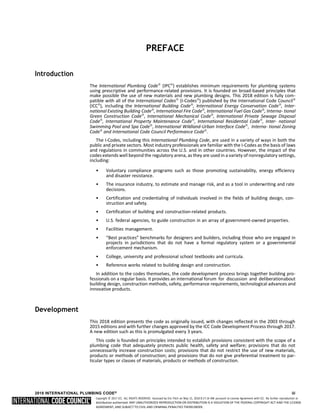
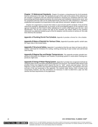
For the development of the 2021 edition of the I-Codes, there will be two groups of code devel-
opment committees and they will meet in separate years. Note that these are tentative groupings.
Group A Codes
(Heard in 2018, Code Change Proposals
Deadline: January 8, 2018)
Group B Codes
(Heard in 2019, Code Change Proposals
Deadline: January 7, 2019)
International Building Code
– Egress (Chapters 10, 11, Appendix E)
– Fire Safety (Chapters 7, 8, 9, 14, 26)
– General (Chapters 2–6, 12, 27–33,
Appendices A, B, C, D, K, N)
Administrative Provisions (Chapter 1 of allcodes
except IECC, IRC and IgCC, administra- tive
updates to currently referenced stan- dards,
and designated definitions)
International Fire Code International Building Code
– Structural (Chapters 15–25, Appendices F,
G, H, I, J, L, M)
International Fuel Gas Code International Existing Building Code
International Mechanical Code International Energy Conservation Code—
Commercial
International Plumbing Code International Energy Conservation Code—
Residential
– IECC—Residential
– IRC—Energy (Chapter 11)
International Property Maintenance Code International Green Construction Code
(Chapter 1)
International Private Sewage Disposal Code International Residential Code
– IRC—Building (Chapters 1–10,
Appendices E, F, H, J, K, L, M, O, Q, R, S, T)
International Residential Code
– IRC—Mechanical (Chapters 12–23)
– IRC—Plumbing (Chapters 25–33,
Appendices G, I, N, P)
International Swimming Pool and Spa Code
International Wildland-Urban Interface Code
International Zoning Code
Note: Proposed changes to the ICC Performance Code will be heard by the code development committee noted in brack-
ets [ ] in the text of the ICC Performance Code.
Code change proposals submitted for code sections that have a letter designation in front of them
will be heard by the respective committee responsible for such code sections. Because differ- ent
committees hold Committee Action Hearings in different years, proposals for the IPC will be heard by
committees in both the 2018 (Group A) and the 2019 (Group B) code development cycles.
For instance, every section of Chapter 1 of this code is designated as the responsibility of the
Administrative Code Development Committee, which is part of the Group B portion of the hearings.
This committee will hold its Committee Action Hearings in 2019 to consider code change proposals for
Chapter 1 of all I-Codes except the International Energy Conservation Code, International Resi- dential
Code and International Green Construction Code. Therefore, any proposals received for Chapter 1 of
this code will be assigned to the Administrative Code Development Committee for con- sideration in
2019.
It is very important that anyone submitting code change proposals understands which code
development committee is responsible for the section ofthe code that is the subject of the code change
proposal. For further information on the Code Development Committee responsibilities,please visit
the ICC website at www.iccsafe.org/scoping.
2018 INTERNATIONAL PLUMBING CODE® v](https://image.slidesharecdn.com/2018-ipc-international-plumbing-code-241129135518-3483e2e4/85/2018-IPC-International-Plumbing-Code-pdf-6-320.jpg)
![Copyright © 2017 ICC. ALL RIGHTS RESERVED. Accessed by Eric Fitch on May 15, 2018 8:17:14 AM pursuant to License Agreement with ICC. No further reproduction or
distribution authorized. ANY UNAUTHORIZED REPRODUCTION OR DISTRIBUTION IS A VIOLATION OF THE FEDERAL COPYRIGHT ACT AND THE LICENSE
AGREEMENT, AND SUBJECT TO CIVIL AND CRIMINAL PENALTIES THEREUNDER.
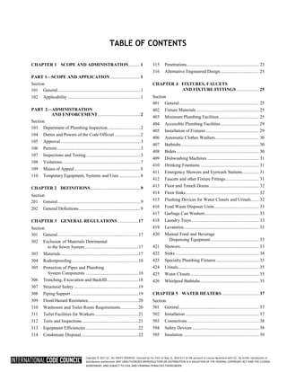
Marginal Markings
Solid vertical lines in the margins within the body of the code indicate a technical change from the
requirements of the 2015 edition. Deletion indicators in the form of an arrow (➡) are provided in
the margin where an entire section, paragraph, exception or table has been deleted or an item in a
list of items or a table has been deleted.
A single asterisk [*] placed in the margin indicates that text or a table has been relocated within the
code. A double asterisk [**] placed in the margin indicates that the text or table immediately following
it has been relocated there from elsewhere in the code. The following table indicates such relocations
in the 2018 edition of the International Plumbing Code.
2018 LOCATION 2015 LOCATION
802.2 804.1
Coordination of the International Codes
The coordination of technical provisions is one of the strengths of the ICC family of model codes. The
codes can be used as a complete set of complementary documents, which will provide users with full
integration and coordination of technical provisions. Individual codes can also be used in subsets or as
stand-alone documents. To make sure that each individual code is as complete as pos- sible, some
technical provisions that are relevant to more than one subject area are duplicated in some of the
model codes. This allows users maximum flexibility in their application of the I-Codes.
Italicized Terms
Words and terms defined in Chapter 2, Definitions, are italicized where they appear in code text and
the Chapter 2 definition applies. Where such words and terms are not italicized, common-use defi-
nitions apply. The words and terms selected have code-specific definitions that the user should read
carefully to facilitate better understanding of the code.
Adoption
The International Code Council maintains a copyright in all of its codes and standards. Maintaining
copyright allows the ICC to fund its mission through sales of books, in both print and electronic for-
mats. The ICC welcomes adoption of its codes by jurisdictions that recognize and acknowledge the ICC’s
copyright in the code, and further acknowledge the substantial shared value of the public/pri- vate
partnership for code development between jurisdictions and the ICC.
The ICC also recognizes the need for jurisdictions to make laws available to the public. All I-Codes
and I-Standards, along with the laws of many jurisdictions, are available for free in a nondownloadable
form on the ICC’s website. Jurisdictions should contact the ICC at adop- tions@iccsafe.org to learn how
to adopt and distribute laws based on the International Plumb- ing Code in a manner that
provides necessary access, while maintaining the ICC’s copyright.
vi 2018 INTERNATIONAL PLUMBING CODE®](https://image.slidesharecdn.com/2018-ipc-international-plumbing-code-241129135518-3483e2e4/85/2018-IPC-International-Plumbing-Code-pdf-7-320.jpg)
![Copyright © 2017 ICC. ALL RIGHTS RESERVED. Accessed by Eric Fitch on May 15, 2018 8:17:14 AM pursuant to License Agreement with ICC. No further reproduction or
distribution authorized. ANY UNAUTHORIZED REPRODUCTION OR DISTRIBUTION IS A VIOLATION OF THE FEDERAL COPYRIGHT ACT AND THE LICENSE
AGREEMENT, AND SUBJECT TO CIVIL AND CRIMINAL PENALTIES THEREUNDER.
To facilitate adoption, several sections of this code contain blanks for fill-in information that
needs to be supplied by the adopting jurisdiction as part of the adoption legislation. For this
code, please see:
Section 101.1. Insert: [NAME OF JURISDICTION]
Section 106.6.2. Insert: [APPROPRIATE SCHEDULE]
Section 106.6.3. Insert: [PERCENTAGES IN TWO LOCATIONS]
Section 108.4. Insert: [OFFENSE, DOLLAR AMOUNT, NUMBER OF DAYS]
Section 108.5. Insert: [DOLLAR AMOUNT IN TWO LOCATIONS]
Section 305.4.1. Insert: [NUMBER OF INCHES IN TWO LOCATIONS]
Section 903.1. Insert: [NUMBER OF INCHES]
2018 INTERNATIONAL PLUMBING CODE® vii](https://image.slidesharecdn.com/2018-ipc-international-plumbing-code-241129135518-3483e2e4/85/2018-IPC-International-Plumbing-Code-pdf-8-320.jpg)


![Copyright © 2017 ICC. ALL RIGHTS RESERVED. Accessed by Eric Fitch on May 15, 2018 8:17:14 AM pursuant to License Agreement with ICC. No further reproduction or
distribution authorized. ANY UNAUTHORIZED REPRODUCTION OR DISTRIBUTION IS A VIOLATION OF THE FEDERAL COPYRIGHT ACT AND THE LICENSE
AGREEMENT, AND SUBJECT TO CIVIL AND CRIMINAL PENALTIES THEREUNDER.
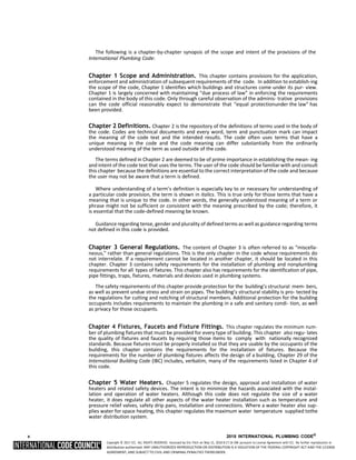
CHAPTER 1
SCOPE AND ADMINISTRATION
User note:
About this chapter: Chapter 1 establishes the limits of applicability of this code and describes how the code is to be applied and enforced.
Chapter 1 is in two parts: Part 1—Scope and Application (Sections 101–102) and Part 2—Administration and Enforcement (Sections 103–
110). Section 101 identifies which buildings and structures come under its purview and references other I-Codes as applicable. Standards and
codes are scoped to the extent referenced (see Section 102.8).
This code is intended to be adopted as a legally enforceable document and it cannot be effective without adequate provisions for its adminis-
tration and enforcement. The provisions of Chapter 1 establish the authority and duties of the code official appointed by the authority having
jurisdiction and also establish the rights and privileges of the design professional, contractor and property owner.
PART 1—SCOPE AND APPLICATION
SECTION 101
GENERAL
[A] 101.1 Title. These regulations shall be known as the
Plumbing Code of [NAME OF JURISDICTION] hereinafter referred
to as “this code.”
[A] 101.2 Scope. The provisions of this code shall apply to
the erection, installation, alteration, repairs, relocation,
replacement, addition to, use or maintenance of plumbing
systems within this jurisdiction. This code shall regulate non-
flammable medical gas, inhalation anesthetic, vacuum piping,
nonmedical oxygen systems and sanitary and condensate vac-
uum collection systems. The installation of fuel gas distribu-
tion piping and equipment, fuel-gas-fired water heaters and
water heater venting systems shall be regulated by the Inter-
national Fuel Gas Code. Provisions in the appendices shall not
apply unless specifically adopted.
Exception: Detached one- and two-family dwellings and
multiple single-family dwellings (townhouses) not morethan
three stories high with separate means of egress and their
accessory structures shall comply with the Interna- tional
Residential Code.
[A] 101.3 Intent. The purpose of this code is to establish
minimum standards to provide a reasonable level of safety,
health, property protection and public welfare by regulating and
controlling the design, construction, installation, quality of
materials, location, operation and maintenance or use of
plumbing equipment and systems.
[A] 101.4 Severability. If any section, subsection, sentence,
clause or phrase of this code is for any reason held to be
unconstitutional, such decision shall not affect the validity of
the remaining portions of this code.
SECTION 102
APPLICABILITY
[A] 102.1 General. Where there is a conflict between a gen-
eral requirement and a specific requirement, the specific
requirement shall govern. Where, in any specific case, differ-
ent sections of this code specify different materials, methods
of construction or other requirements, the most restrictive shall
govern.
[A] 102.2 Existing installations. Plumbing systems lawfully in
existence at the time of the adoption of this code shall be
permitted to have their use and maintenance continued if the
use, maintenance or repair is in accordance with the original
design and hazard to life, health or property is not created by
such plumbing system.
[A] 102.2.1 Existing buildings. Additions, alterations,
renovations or repairs related to building or structural issues
shall be regulated by the International Existing Building
Code.
[A] 102.3 Maintenance. Plumbing systems, materials and
appurtenances, both existing and new, and parts thereof, shall
be maintained in proper operating condition in accordance with
the original design in a safe and sanitary condition. Devices or
safeguards required by this code shall be main- tained in
compliance with the edition of the code under which they were
installed.
The owner or the owner’s authorized agent shall be
responsible for maintenance of plumbing systems. To deter-
mine compliance with this provision, the code official shall
have the authority to require any plumbing system to be rein-
spected.
[A] 102.4 Additions, alterations or repairs. Additions,
alterations, renovations or repairs to any plumbing systemshall
conform to that required for a new plumbing system without
requiring the existing plumbing system to complywith all the
requirements of this code. Additions, alterationsor repairs
shall not cause an existing system to become unsafe, insanitary
or overloaded.
Minor additions, alterations, renovations and repairs to
existing plumbing systems shall meet the provisions for new
construction, unless such work is done in the same manner
and arrangement as was in the existing system, is not hazard-
ous and is approved.
[A] 102.5 Change in occupancy. It shall be unlawful to make
any change in the occupancy of any structure that will subject
the structure to any special provision of this codeapplicable to
the new occupancy without approval of the code official. The
code official shall certify that such structure](https://image.slidesharecdn.com/2018-ipc-international-plumbing-code-241129135518-3483e2e4/85/2018-IPC-International-Plumbing-Code-pdf-20-320.jpg)

![Copyright © 2017 ICC. ALL RIGHTS RESERVED. Accessed by Eric Fitch on May 15, 2018 8:17:14 AM pursuant to License Agreement with ICC. No further reproduction or
distribution authorized. ANY UNAUTHORIZED REPRODUCTION OR DISTRIBUTION IS A VIOLATION OF THE FEDERAL COPYRIGHT ACT AND THE LICENSE
AGREEMENT, AND SUBJECT TO CIVIL AND CRIMINAL PENALTIES THEREUNDER.
SCOPE AND ADMINISTRATION
meets the intent of the provisions of law governing building
construction for the proposed new occupancy and that such
change of occupancy does not result in any hazard to the pub-
lic health, safety or welfare.
[A] 102.6 Historic buildings. The provisions of this code
relating to the construction, alteration, repair, enlargement,
restoration, relocation or moving of buildings or structures shall
not be mandatory for existing buildings or structures identified
and classified by the state or local jurisdiction as historic
buildings where such buildings or structures are judged by the
code official to be safe and in the public inter- est of health,
safety and welfare regarding any proposed con- struction,
alteration, repair, enlargement, restoration, relocation or
moving of buildings.
[A] 102.7 Moved buildings. Except as determined by Sec- tion
102.2, plumbing systems that are a part of buildings or
structures moved into or within the jurisdiction shall comply
with the provisions of this code for new installations.
[A] 102.8 Referenced codes and standards. The codes and
standards referenced in this code shall be those that are listed in
Chapter 15 and such codes and standards shall be consid- ered
as part of the requirements of this code to the prescribed extent
of each such reference and as further regulated in Sec- tions
102.8.1 and 102.8.2.
[A] 102.8.1 Conflicts. Where conflicts occur between pro-
visions of this code and the referenced standards, the pro-
visions of this code shall apply.
[A] 102.8.2 Provisions in referenced codes and stan-
dards. Where the extent of the reference to a referenced
code or standard includes subject matter that is within the
scope of this code, the provisions of this code, as applica-
ble, shall take precedence over the provisions in the refer-
enced code or standard.
[A] 102.9 Requirements not covered by code. Any require-
ments necessary for the strength, stability or proper operation
of an existing or proposed plumbing system, or for the public
safety, health and general welfare, not specifically covered by
this code shall be determined by the code official.
[A] 102.10 Other laws. The provisions of this code shall not be
deemed to nullify any provisions of local, state or federal law.
[A] 102.11 Application of references. Reference to chapter
section numbers, or to provisions not specifically identified
by number, shall be construed to refer to such chapter, section
or provision of this code.
PART 2—ADMINISTRATION AND ENFORCEMENT
SECTION 103
DEPARTMENT OF PLUMBING INSPECTION
[A] 103.1 General. The department of plumbing inspection
is hereby created and the executive official in charge thereof
shall be known as the code official.
[A] 103.2 Appointment. The code official shall be appointed
by the chief appointing authority of the jurisdiction.
[A] 103.3 Deputies. In accordance with the prescribed proce-
dures of this jurisdiction and with the concurrence of the
appointing authority, the code official shall have the authority
to appoint a deputy code official, other related technical offi-
cers, inspectors and other employees. Such employees shall
have powers as delegated by the code official.
[A] 103.4 Liability. The code official, member of the board
of appeals or employee charged with the enforcement of this
code, while acting for the jurisdiction in good faith and with-
out malice in the discharge of the duties required by this code
or other pertinent law or ordinance, shall not thereby be ren-
dered civilly or criminally liable personally, and is hereby
relieved from all personal liability for any damage accruing
to persons or property as a result of any act or by reason of an
act or omission in the discharge of official duties.
[A] 103.4.1 Legal defense. Any suit or criminal complaint
instituted against any officer or employee because of an
act performed by that officer or employee in the lawful
discharge of duties and under the provisions of this code
shall be defended by the legal representative of the juris-
diction until the final termination of the proceedings. The
code official or any subordinate shall not be liable for costs
in any action, suit or proceeding that is instituted in
pursuance of the provisions of this code.
SECTION 104
DUTIES AND POWERS OF THE CODE OFFICIAL
[A] 104.1 General. The code official is hereby authorized and
directed to enforce the provisions of this code. The code official
shall have the authority to render interpretations of this code
and to adopt policies and procedures in order to clarify the
application of its provisions. Such interpretations, policies and
procedures shall be in compliance with the intent and purpose
of this code. Such policies and procedures shall not have the
effect of waiving requirements specificallypro- vided for in this
code.
[A] 104.2 Applications and permits. The code official shall
receive applications, review construction documents and issue
permits for the installation and alteration of plumbing systems,
inspect the premises for which such permits have been issued,
and enforce compliance with the provisions of this code.
[A] 104.3 Inspections. The code official shall make all the
required inspections, or shall accept reports of inspection by
approved agencies or individuals. Reports of such inspections
shall be in writing and be certified by a responsible officer of
such approved agency or by the responsible individual. The
code official is authorized to engage such expert opinion as
deemed necessary to report on unusual technical issues that
arise, subject to the approval of the appointing authority.
[A] 104.4 Right of entry. Where it is necessary to make an
inspection to enforce the provisions of this code, or where the
code official has reasonable cause to believe that there exists
in any building or on any premises any conditions or viola-
2 2018 INTERNATIONAL PLUMBING CODE®](https://image.slidesharecdn.com/2018-ipc-international-plumbing-code-241129135518-3483e2e4/85/2018-IPC-International-Plumbing-Code-pdf-22-320.jpg)
![Copyright © 2017 ICC. ALL RIGHTS RESERVED. Accessed by Eric Fitch on May 15, 2018 8:17:14 AM pursuant to License Agreement with ICC. No further reproduction or
distribution authorized. ANY UNAUTHORIZED REPRODUCTION OR DISTRIBUTION IS A VIOLATION OF THE FEDERAL COPYRIGHT ACT AND THE LICENSE
AGREEMENT, AND SUBJECT TO CIVIL AND CRIMINAL PENALTIES THEREUNDER.
SCOPE AND ADMINISTRATION
tions of this code that make the building or premises unsafe,
insanitary, dangerous or hazardous, the code official shall have
the authority to enter the building or premises at all rea- sonable
times to inspect or to perform the duties imposed upon the
code official by this code. If such building or prem- ises is
occupied, the code official shall present credentials to the
occupant and request entry. If such building or premises is
unoccupied, the code official shall first make a reasonable effort
to locate the owner, the owner’s authorized agent or other
person having charge or control of the building or premises and
request entry. If entry is refused, the code offi- cial shall have
recourse to every remedy provided by law to secure entry.
Where the code official shall have first obtained a proper
inspection warrant or other remedy provided by law to secure
entry, the owner, owner’s authorized agent, occupant or per-
son having charge, care or control of any building or premises
shall not fail or neglect, after proper request is made as herein
provided, to promptly permit entry therein by the code offi- cial
for the purpose of inspection and examination pursuant to this
code.
[A] 104.5 Identification. The code official shall carry proper
identification when inspecting structures or premises in the
performance of duties under this code.
[A] 104.6 Notices and orders. The code official shall issue
all necessary notices or orders to ensure compliance with this
code.
[A] 104.7 Department records. The code official shall keep
official records of applications received, permits and certifi-
cates issued, fees collected, reports of inspections, and notices
and orders issued. Such records shall be retained in the official
records for the period required for the retention of public
records.
SECTION 105
APPROVAL
[A] 105.1 Modifications. Where there are practical difficul-
ties involved in carrying out the provisions of this code, the
code official shall have the authority to grant modifications
for individual cases, upon application of the owner or owner’s
authorized agent, provided that the code official shall first find
that special individual reason makes the strict letterof this code
impractical and the modification conforms to the intent and
purpose of this code and that such modificationdoes not lessen
health, life and fire safety requirements. The details of action
granting modifications shall be recorded and entered in the files
of the plumbing inspection department.
[A] 105.2 Alternative materials, design and methods of
construction and equipment. The provisions of this code are
not intended to prevent the installation of any material orto
prohibit any design or method of construction not specifi- cally
prescribed by this code, provided that any such alterna- tive has
been approved. An alternative material or method of
construction shall be approved where the code official finds that
the proposed design is satisfactory and complies with the intent
of the provisions of this code, and that the material, method or
work offered is, for the purpose intended, not less than the
equivalent of that prescribed in this code in quality,
strength, effectiveness, fire resistance, durability and safety.
Where the alternative material, design or method of construc-
tion is not approved, the code official shall respond in writ- ing,
stating the reasons why the alternative was not approved.
[A] 105.2.1 Research reports. Supporting data, where
necessary to assist in the approval of materials or assem-
blies not specifically provided for in this code, shall con- sist
of valid research reports from approved sources.
[A] 105.3 Required testing. Where there is insufficient evi-
dence of compliance with the provisions of this code, or evi-
dence that a material or method does not conform to the
requirements of this code, or in order to substantiate claims
for alternate materials or methods, the code official shall have
the authority to require tests as evidence of compliance to be
made at no expense to the jurisdiction.
[A] 105.3.1 Test methods. Test methods shall be as speci-
fied in this code or by other recognized test standards. In
the absence of recognized and accepted test methods, the
code official shall approve the testing procedures.
[A] 105.3.2 Testing agency. Tests shall be performed by an
approved agency.
[A] 105.3.3 Test reports. Reports of tests shall be retained
by the code official for the period required for retention of
public records.
[A] 105.4 Approved materials and equipment. Materials,
equipment and devices approved by the code official shall be
constructed and installed in accordance with such approval.
[A] 105.4.1 Material and equipment reuse. Materials,
equipment and devices shall not be reused unless such ele-
ments have been reconditioned, tested, placed in good and
proper working condition and approved.
SECTION 106
PERMITS
[A] 106.1 Where required. Any owner, owner’s authorized
agent or contractor who desires to construct, enlarge, alter,
repair, move, demolish or change the occupancy of a building
or structure, or to erect, install, enlarge, alter, repair, remove,
convert or replace any plumbing system, the installation of
which is regulated by this code, or to cause any such work to be
performed, shall first make application to the code official and
obtain the required permit for the work.
[A] 106.1.1 Annual permit. Instead of an individual con-
struction permit for each alteration to an already approved
system or equipment or appliance installation, the code
official is authorized to issue an annual permit upon appli-
cation therefor to any person, firm or corporation regularly
employing one or more qualified tradespersons in the
building, structure or on the premises owned or operatedby
the applicant for the permit.
[A] 106.1.2 Annual permit records. The person to whom
an annual permit is issued shall keep a detailed record of
alterations made under such annual permit. The code offi-
cial shall have access to such records at all times or such
records shall be filed with the code official as designated.
2018 INTERNATIONAL PLUMBING CODE® 3](https://image.slidesharecdn.com/2018-ipc-international-plumbing-code-241129135518-3483e2e4/85/2018-IPC-International-Plumbing-Code-pdf-23-320.jpg)
![Copyright © 2017 ICC. ALL RIGHTS RESERVED. Accessed by Eric Fitch on May 15, 2018 8:17:14 AM pursuant to License Agreement with ICC. No further reproduction or
distribution authorized. ANY UNAUTHORIZED REPRODUCTION OR DISTRIBUTION IS A VIOLATION OF THE FEDERAL COPYRIGHT ACT AND THE LICENSE
AGREEMENT, AND SUBJECT TO CIVIL AND CRIMINAL PENALTIES THEREUNDER.
SCOPE AND ADMINISTRATION
[A] 106.2 Exempt work. The following work shall be exempt
from the requirement for a permit:
1. The stopping of leaks in drains, water, soil, waste or
vent pipe provided, however, that if any concealed trap,
drainpipe, water, soil, waste or vent pipe becomes
defective and it becomes necessary to remove and replace
the same with new material, such work shall be
considered as new work and a permit shall be obtained
and inspection made as provided in this code.
2. The clearing of stoppages or the repairing of leaks in
pipes, valves or fixtures, and the removal and reinstal-
lation of water closets, provided that such repairs do
not involve or require the replacement or rearrange- ment
of valves, pipes or fixtures.
Exemption from the permit requirements of this code shall
not be deemed to grant authorization for any work to be done in
violation of the provisions of this code or any other laws or
ordinances of this jurisdiction.
[A] 106.3 Application for permit. Each application for a
permit, with the required fee, shall be filed with the code offi-
cial on a form furnished for that purpose and shall contain a
general description of the proposed work and its location. The
application shall be signed by the owner or owner’s autho- rized
agent. The permit application shall indicate the pro- posed
occupancy of all parts of the building and of that portion of the
site or lot, if any, not covered by the building or structure and
shall contain such other information required by the code
official.
[A] 106.3.1 Construction documents. Construction doc-
uments, engineering calculations, diagrams and other such
data shall be submitted in two or more sets with each
application for a permit. The code official shall require
construction documents, computations and specifications
to be prepared and designed by a registered design profes-
sional where required by state law. Construction docu-
ments shall be drawn to scale and shall be of sufficient
clarity to indicate the location, nature and extent of the work
proposed and show in detail that the work conformsto the
provisions of this code. Construction documents for
buildings more than two stories in height shall indicate
where penetrations will be made for pipes, fittings and
components and shall indicate the materials and methods
for maintaining required structural safety, fire-resistance
rating and fireblocking.
Exception: The code official shall have the authority to
waive the submission of construction documents, cal-
culations or other data if the nature of the work applied
for is such that reviewing of construction documents is
not necessary to determine compliance with this code.
[A] 106.3.2 Preliminary inspection. Before a permit is
issued, the code official shall be authorized to inspect and
evaluate the systems, equipment, buildings, devices, prem-
ises and spaces or areas to be used.
[A] 106.3.3 Time limitation of application. An applica-
tion for a permit for any proposed work shall be deemed to
have been abandoned 180 days after the date of filing,unless
such application has been pursued in good faith or a permit
has been issued; except that the code official shall
have the authority to grant one or more extensions of time
for additional periods not exceeding 180 days each. The
extension shall be requested in writing and justifiable cause
demonstrated.
[A] 106.4 By whom application is made. Application for a
permit shall be made by the person or agent to install all or part
of any plumbing system. The applicant shall meet all
qualifications established bystatute, or by rules promulgated by
this code, or by ordinance or by resolution. The full name and
address of the applicant shall be stated in the application.
[A] 106.5 Permit issuance. The application, construction
documents and other data filed by an applicant for permit shall
be reviewed by the code official. If the code officialfinds that
the proposed work conforms to the requirements of this code
and all laws and ordinances applicable thereto, and that the fees
specified in Section 106.6 have been paid, a per- mit shall be
issued to the applicant.
[A] 106.5.1 Approved construction documents. When
the code official issues the permit where construction doc-
uments are required, the construction documents shall be
endorsed in writing and stamped “APPROVED.” Such
approved construction documents shall not be changed,
modified or altered without authorization from the code
official. Work shall be done in accordance with the approved
construction documents.
The code official shall have the authority to issue a per-
mit for the construction of a part of a plumbing system
before the entire construction documents for the whole
system have been submitted or approved, provided that
adequate information and detailed statements have been
filed complying with all pertinent requirements of this code.
The holders of such permit shall proceed at their own risk
without assurance that the permit for the entire plumbing
system will be granted.
[A] 106.5.2 Validity. The issuance of a permit or approval
of construction documents shall not be construed to be a
permit for, or an approval of, any violation of any of the
provisions of this code or any other ordinance of the juris-
diction. A permit presuming to give authority to violate or
cancel the provisions of this code shall not be valid.
The issuance of a permit based on construction docu-
ments and other data shall not prevent the code official from
thereafter requiring the correction of errors in said
construction documents and other data or from preventing
building operations being carried on thereunder where in
violation of this code or of other ordinances of this juris-
diction.
[A] 106.5.3 Expiration. Every permit issued by the code
official under the provisions of this code shall expire by
limitation and become null and void if the work authorized
by such permit is not commenced within 180 days from
the date of such permit, or if the work authorized by such
permit is suspended or abandoned at any time after thework
is commenced for a period of 180 days. Before such work
can be recommenced, a new permit shall be firstobtained and
the fee therefor shall be one-half the amount required for a
new permit for such work, provided that changes have not
been made and will not be made in the](https://image.slidesharecdn.com/2018-ipc-international-plumbing-code-241129135518-3483e2e4/85/2018-IPC-International-Plumbing-Code-pdf-24-320.jpg)

![Copyright © 2017 ICC. ALL RIGHTS RESERVED. Accessed by Eric Fitch on May 15, 2018 8:17:14 AM pursuant to License Agreement with ICC. No further reproduction or
distribution authorized. ANY UNAUTHORIZED REPRODUCTION OR DISTRIBUTION IS A VIOLATION OF THE FEDERAL COPYRIGHT ACT AND THE LICENSE
AGREEMENT, AND SUBJECT TO CIVIL AND CRIMINAL PENALTIES THEREUNDER.
SCOPE AND ADMINISTRATION
original construction documents for such work, and pro-
vided further that such suspension or abandonment has not
exceeded 1 year.
[A] 106.5.4 Extensions. Any permittee holding an unex-
pired permit shall have the right to apply for an extension
of the time within which the permittee will commence work
under that permit when work is unable to be com- menced
within the time required by this section for good and
satisfactory reasons. The code official shall extend the time
for action by the permittee for a period not exceeding 180
days if there is reasonable cause. A permit shall not be
extended more than once. The fee for an extension shall be
one-half the amount required for a new permit for such work.
[A] 106.5.5 Suspension or revocation of permit. The code
official shall have the authority to suspend or revokea
permit issued under the provisions of this code wherever the
permit is issued in error or on the basis of incorrect,
inaccurate or incomplete information, or in violation ofany
ordinance or regulation or any of the provisions of this code.
[A] 106.5.6 Retention of construction documents. Oneset
of approved construction documents shall be retained bythe
code official for a period of not less than 180 days from date
of completion of the permitted work, or as required by state
or local laws.
One set of approved construction documents shall be
returned to the applicant, and said set shall be kept on the
site of the building or work at all times during which the
work authorized thereby is in progress.
[A] 106.5.7 Previous approvals. This code shall not require
changes in the construction documents, construc- tion or
designated occupancy of a structure for which a lawful
permit has been heretofore issued or otherwise law- fully
authorized, and the construction of which has been pursued
in good faith within 180 days after the effective date of this
code and has not been abandoned.
[A] 106.5.8 Posting of permit. The permit or a copy shall
be kept on the site of the work until the completion of the
project.
[A] 106.6 Fees. A permit shall not be issued until the fees
prescribed in Section 106.6.2 have been paid, and an amend-
ment to a permit shall not be released until the additional fee,
if any, due to an increase of the plumbing systems, has been
paid.
[A] 106.6.1 Work commencing before permit issuance.
Any person who commences any work on a plumbing sys-
tem before obtaining the necessary permits shall be subject
to 100 percent of the usual permit fee in addition to the
required permit fees.
[A] 106.6.2 Fee schedule. The fees for all plumbing work
shall be as indicated in the following schedule:
[JURISDICTION TO INSERT APPROPRIATE SCHEDULE]
[A] 106.6.3 Fee refunds. The code official shall authorize
the refunding of fees as follows:
1. The full amount of any fee paid hereunder that was
erroneously paid or collected.
2. Not more than [SPECIFY PERCENTAGE] percent ofthe
permit fee paid where work has been done undera
permit issued in accordance with this code.
3. Not more than [SPECIFY PERCENTAGE] percent ofthe
plan review fee paid where an application for a permit
for which a plan review fee has been paid is withdrawn
or canceled before any plan review effort has been
expended.
The code official shall not authorize the refunding of any
fee paid except upon written application filed by the original
permittee not later than 180 days after the date of fee
payment.
SECTION 107
INSPECTIONS AND TESTING
[A] 107.1 General. The code official is authorized to conduct
such inspections as are deemed necessary to determine com-
pliance with the provisions of this code. Construction or work
for which a permit is required shall be subject to inspection by
the code official, and such construction or work shall remain
visible and able to be accessed for inspection pur- poses until
approved. Approval as a result of an inspection shall not be
construed to be an approval of a violation of the provisions of
this code or of other ordinances of the jurisdic- tion. Inspections
presuming to give authority to violate orcancel the provisions
of this code or of other ordinances ofthe jurisdiction shall not
be valid. It shall be the duty of the permit applicant to cause the
work to remain visible and able to be accessed for inspection
purposes. Neither the code offi- cial nor the jurisdiction shall be
liable for expense entailed in the removal or replacement of any
material required to allow inspection.
[A] 107.2 Required inspections and testing. The code offi-
cial, upon notification from the permit holder or the permit
holder’s agent, shall make the following inspections and such
other inspections as necessary, and shall either release that
portion of the construction or shall notify the permit holder or
an agent of any violations that must be corrected. The holder
of the permit shall be responsible for the scheduling of such
inspections.
1. Underground inspection shall be made after trenches or
ditches are excavated and bedded, piping installed, and
before any backfill is put in place.
2. Rough-in inspection shall be made after the roof, fram-
ing, fireblocking, firestopping, draftstopping and brac-
ing is in place and all sanitary, storm and water
distribution piping is roughed-in, and prior to the instal-
lation of wall or ceiling membranes.
3. Final inspection shall be made after the building is
complete, all plumbing fixtures are in place and prop-
erly connected, and the structure is ready for occu- pancy.
[A] 107.2.1 Other inspections. In addition to the inspec-
tions specified in Section 107.2, the code official shall be
authorized to make or require other inspections of any
construction work to ascertain compliance with the provi-
sions of this code and other laws that are enforced.
2018 INTERNATIONAL PLUMBING CODE® 5](https://image.slidesharecdn.com/2018-ipc-international-plumbing-code-241129135518-3483e2e4/85/2018-IPC-International-Plumbing-Code-pdf-26-320.jpg)
![Copyright © 2017 ICC. ALL RIGHTS RESERVED. Accessed by Eric Fitch on May 15, 2018 8:17:14 AM pursuant to License Agreement with ICC. No further reproduction or
distribution authorized. ANY UNAUTHORIZED REPRODUCTION OR DISTRIBUTION IS A VIOLATION OF THE FEDERAL COPYRIGHT ACT AND THE LICENSE
AGREEMENT, AND SUBJECT TO CIVIL AND CRIMINAL PENALTIES THEREUNDER.
SCOPE AND ADMINISTRATION
[A] 107.2.2 Inspection requests. It shall be the duty of the
holder of the permit or their duly authorized agent to notify
the code official when work is ready for inspection.It shall
be the duty of the permit holder to provide accessto and
means for inspections of such work that are required by
this code.
[A] 107.2.3 Approval required. Work shall not be done
beyond the point indicated in each successive inspection
without first obtaining the approval of the code official.
The code official, upon notification, shall make the
requested inspections and shall either indicate the portion of
the construction that is satisfactory as completed, ornotify
the permit holder or his or her agent wherein the same fails
to comply with this code. Any portions that do not comply
shall be corrected and such portion shall not be covered or
concealed until authorized by the code official.
[A] 107.2.4 Approved agencies. The code official is
authorized to accept reports of approved inspection agen-
cies, provided that such agencies satisfy the requirements as
to qualifications and reliability.
[A] 107.2.5 Evaluation and follow-up inspection ser-
vices. Prior to the approval of a closed, prefabricated
plumbing system and the issuance of a plumbing permit,
the code official shall require the submittal of an evalua- tion
report on each prefabricated plumbing system indicat- ing
the complete details of the plumbing system, includinga
description of the system and its components, the basison
which the plumbing system is being evaluated, test results
and similar information, and other data as neces- sary for the
code official to determine conformance to this code.
[A] 107.2.5.1 Evaluation service. The code official
shall designate the evaluation service of an approved
agency as the evaluation agency, and review such
agency’s evaluation report for adequacy and confor-
mance to this code.
[A] 107.2.5.2 Follow-up inspection. Except where ready
access is provided to all plumbing systems, ser- vice
equipment and accessories for complete inspection at the
site without disassembly or dismantling, the code official
shall conduct the frequency of in-plant inspec- tions
necessary to ensure conformance to the approved
evaluation report or shall designate an independent,
approved inspection agency to conduct such inspec-
tions. The inspection agency shall furnish the code offi-
cial with the follow-up inspection manual and a report
of inspections on request, and the plumbing system shall
have an identifying label permanently affixed to the
system indicating that factory inspections have been
performed.
[A] 107.2.5.3 Test and inspection records. Required test
and inspection records shall be available to the code
official at all times during the fabrication of the plumbing
system and the erection of the building, or such records
as the code official designates shall befiled.
[A] 107.3 Special inspections. Special inspections of alter-
native engineered design plumbing systems shall be con-
ducted in accordance with Sections 107.3.1 and 107.3.2.
[A] 107.3.1 Periodic inspection. The registered design
professional or designated inspector shall periodically
inspect and observe the alternative engineered design to
determine that the installation is in accordance with the
approved construction documents. Discrepancies shall be
brought to the immediate attention of the plumbing con-
tractor for correction. Records shall be kept of all inspec-
tions.
[A] 107.3.2 Written report. The registered design profes-
sional shall submit a final report in writing to the code
official upon completion of the installation, certifying that
the alternative engineered design conforms to the approved
construction documents. A notice of approval for the
plumbing system shall not be issued until a written
certification has been submitted.
[A] 107.4 Testing. Plumbing work and systems shall be tested
as required in Section 312 and in accordance with Sec- tions
107.4.1 through 107.4.3. Tests shall be made by the per- mit
holder and observed by the code official.
[A] 107.4.1 New, altered, extended or repaired systems.
New plumbing systems and parts of existing systems that
have been altered, extended or repaired shall be tested as
prescribed herein to disclose leaks and defects, except that
testing is not required in the following cases:
1 In any case that does not include addition to,
replacement, alteration or relocation of any water
supply, drainage or vent piping.
2. In any case where plumbing equipment is set up
temporarily for exhibition purposes.
[A] 107.4.2 Equipment, material and labor for tests.
Equipment, material and labor required for testing a
plumbing system or part thereof shall be furnished by the
permit holder.
[A] 107.4.3 Reinspection and testing. Where any work or
installation does not pass any initial test or inspection, the
necessary corrections shall be made to comply with this
code. The work or installation shall then be resubmitted to
the code official for inspection and testing.
[A] 107.5 Approval. After the prescribed tests and inspec-
tions indicate that the work complies in all respects with this
code, a notice of approval shall be issued by the code official.
[A] 107.5.1 Revocation. The code official is authorized
to, in writing, suspend or revoke a notice of approval issued
under the provisions of this code wherever the notice is
issued in error, or on the basis of incorrect infor- mation
supplied, or where it is determined that the build- ing or
structure, premise or portion thereof is in violationof any
ordinance or regulation or any of the provisions of this code.
[A] 107.6 Temporary connection. The code official shallhave
the authority to authorize the temporary connection of the
building or system to the utilitysource for the purpose of testing
plumbing systems or for use under a temporary certif- icate of
occupancy.
6 2018 INTERNATIONAL PLUMBING CODE®](https://image.slidesharecdn.com/2018-ipc-international-plumbing-code-241129135518-3483e2e4/85/2018-IPC-International-Plumbing-Code-pdf-27-320.jpg)
![Copyright © 2017 ICC. ALL RIGHTS RESERVED. Accessed by Eric Fitch on May 15, 2018 8:17:14 AM pursuant to License Agreement with ICC. No further reproduction or
distribution authorized. ANY UNAUTHORIZED REPRODUCTION OR DISTRIBUTION IS A VIOLATION OF THE FEDERAL COPYRIGHT ACT AND THE LICENSE
AGREEMENT, AND SUBJECT TO CIVIL AND CRIMINAL PENALTIES THEREUNDER.
SCOPE AND ADMINISTRATION
[A] 107.7 Connection of service utilities. A person shall not
make connections from a utility, source of energy, fuel, power,
water system or sewer system to any building or sys- tem that
is regulated by this code for which a permit is required until
authorized by the code official.
SECTION 108
VIOLATIONS
[A] 108.1 Unlawful acts. It shall be unlawful for any person,
firm or corporation to erect, construct, alter, repair, remove,
demolish or utilize any plumbing system, or cause same to be
done, in conflict with or in violation of any of the provisions
of this code.
[A] 108.2 Notice of violation. The code official shall serve a
notice of violation or order to the person responsible for the
erection, installation, alteration, extension, repair, removal or
demolition of plumbing work in violation of the provisions of
this code, or in violation of a detail statement or the approved
construction documents thereunder, or in violation of a per- mit
or certificate issued under the provisions of this code. Such
order shall direct the discontinuance of the illegal action or
condition and the abatement of the violation.
[A] 108.3 Prosecution of violation. If the notice of violation
is not complied with promptly, the code official shall request
the legal counsel of the jurisdiction to institute the appropri-ate
proceeding at law or in equity to restrain, correct or abate such
violation, or to require the removal or termination of the
unlawful occupancy of the structure in violation of the provi-
sions of this code or of the order or direction made pursuant
thereto.
[A] 108.4 Violation penalties. Any person who shall violate
a provision of this code or shall fail to comply with any of the
requirements thereof or who shall erect, install, alter or repair
plumbing work in violation of the approved construction doc-
uments or directive of the code official, or of a permit or cer-
tificate issued under the provisions of this code, shall be guilty
of a [SPECIFY OFFENSE], punishable by a fine of not more than
[AMOUNT] dollars or by imprisonment not exceed- ing [NUMBER
OF DAYS], or both such fine and imprisonment. Each day that a
violation continues after due notice has been served shall be
deemed a separate offense.
[A] 108.5 Stop work orders. Upon notice from the code offi-
cial, work on any plumbing system that is being performed
contrary to the provisions of this code or in a dangerous or
unsafe manner shall immediately cease. Such notice shall be
in writing and shall be given to the owner of the property, orto
the owner’s authorized agent, or to the person performing the
work. The notice shall state the conditions under which work is
authorized to resume. Where an emergency exists,the code
official shall not be required to give a written notice prior to
stopping the work. Any person who shall continueany work
in or about the structure after having been served with a stop
work order, except such work as that person is directed to
perform to remove a violation or unsafe condition, shall be
liable to a fine of not less than [AMOUNT] dollars or more than
[AMOUNT] dollars.
[A] 108.6 Abatement of violation. The imposition of the
penalties herein prescribed shall not preclude the legal officer
of the jurisdiction from instituting appropriate action to pre-
vent unlawful construction or to restrain, correct or abate a
violation, or to prevent illegal occupancy of a building, struc-
ture or premises, or to stop an illegal act, conduct, business or
utilization of the plumbing on or about any premises.
[A] 108.7 Unsafe plumbing. Any plumbing regulated by this
code that is unsafe or that constitutes a fire or health hazard,
insanitary condition, or is otherwise dangerous to human life
is hereby declared unsafe. Any use of plumbing regulated by
this code constituting a hazard to safety, health or public wel-
fare by reason of inadequate maintenance, dilapidation, obso-
lescence, fire hazard, disaster, damage or abandonment is
hereby declared an unsafe use. Any such unsafe equipment is
hereby declared to be a public nuisance and shall be abated
by repair, rehabilitation, demolition or removal.
[A] 108.7.1 Authority to condemn equipment. Wherethe
code official determines that any plumbing, or portion
thereof, regulated by this code has become hazardous to life,
health or property or has become insanitary, the code official
shall order in writing that such plumbing either be removed
or restored to a safe or sanitary condition. A time limit for
compliance with such order shall be specified in the written
notice. A person shall not use or maintain defective
plumbing after receiving such notice.
Where such plumbing is to be disconnected, written
notice as prescribed in Section 108.2 shall be given. In cases
of immediate danger to life or property, such discon- nection
shall be made immediately without such notice.
[A] 108.7.2 Authority to disconnect service utilities. The
code official shall have the authority to authorize dis-
connection of utility service to the building, structure or
system regulated by the technical codes in case of an
emergency, where necessary, to eliminate an immediate
danger to life or property. Where possible, the owner or
the owner’s authorized agent and occupant of the building,
structure or service system shall be notified of the decision
to disconnect utility service prior to taking such action. If not
notified prior to disconnecting, the owner, the owner’s
authorized agent or occupant of the building, structure or
service systems shall be notified in writing, as soon as
practical thereafter.
[A] 108.7.3 Connection after order to disconnect. A
person shall not make connections from any energy, fuel,
power supply or water distribution system or supply energy,
fuel or water to any equipment regulated by this code that
has been disconnected or ordered to be discon- nected by the
code official or the use of which has been ordered to be
discontinued by the code official until the code official
authorizes the reconnection and use of such equipment.
Where any plumbing is maintained in violation of this
code, and in violation of any notice issued pursuant to the
provisions of this section, the code official shall institute any
appropriate action to prevent, restrain, correct or abate the
violation.](https://image.slidesharecdn.com/2018-ipc-international-plumbing-code-241129135518-3483e2e4/85/2018-IPC-International-Plumbing-Code-pdf-28-320.jpg)

![Copyright © 2017 ICC. ALL RIGHTS RESERVED. Accessed by Eric Fitch on May 15, 2018 8:17:14 AM pursuant to License Agreement with ICC. No further reproduction or
distribution authorized. ANY UNAUTHORIZED REPRODUCTION OR DISTRIBUTION IS A VIOLATION OF THE FEDERAL COPYRIGHT ACT AND THE LICENSE
AGREEMENT, AND SUBJECT TO CIVIL AND CRIMINAL PENALTIES THEREUNDER.
SCOPE AND ADMINISTRATION
SECTION 109
MEANS OF APPEAL
[A] 109.1 Application for appeal. Any person shall have the
right to appeal a decision of the code official to the board of
appeals. An application for appeal shall be based on a claim that
the true intent of this code or the rules legally adopted
thereunder have been incorrectly interpreted, the provisions
of this code do not fully apply, or an equally good or better form
of construction is proposed. The application shall befiled on a
form obtained from the code official within 20 days after the
notice was served.
[A] 109.2 Membership of board. The board of appeals shall
consist of five members appointed by the chief appointing
authority as follows: one for 5 years, one for 4 years, one for
3 years, one for 2 years and one for 1 year. Thereafter, each new
member shall serve for 5 years or until a successor has been
appointed.
[A] 109.2.1 Qualifications. The board of appeals shall
consist of five individuals, one from each of the following
professions or disciplines:
1. Registered design professional who is a registered
architect; or a builder or superintendent of building
construction with not less than 10 years’ experience,
5 years of which shall have been in responsible charge
of work.
2. Registered design professional with structural engi-
neering or architectural experience.
3. Registered design professional with mechanical and
plumbing engineering experience; or a mechanical
and plumbing contractor with not less than 10 years’
experience, 5 years of which shall have been in
responsible charge of work.
4. Registered design professional with electrical engi-
neering experience; or an electrical contractor with not
less than 10 years’ experience, 5 years of which shall
have been in responsible charge of work.
5. Registered design professional with fire protection
engineering experience; or a fire protection contrac-
tor with not less than 10 years’ experience, 5 years of
which shall have been in responsible charge of work.
[A] 109.2.2 Alternate members. The chief appointing
authority shall appoint two alternate members who shallbe
called by the board chairman to hear appeals during the
absence or disqualification of a member. Alternate mem-
bers shall possess the qualifications required for board
membership, and shall be appointed for 5 years or until a
successor has been appointed.
[A] 109.2.3 Chairman. The board shall annually select one
of its members to serve as chairman.
[A] 109.2.4 Disqualification of member. A member shall
not hear an appeal in which that member has any personal,
professional or financial interest.
[A] 109.2.5 Secretary. The chief administrative officer shall
designate a qualified clerk to serve as secretary to the board.
The secretary shall file a detailed record of all pro- ceedings
in the office of the chief administrative officer.
[A] 109.2.6 Compensation of members. Compensation
of members shall be determined by law.
[A] 109.3 Notice of meeting. The board shall meet uponnotice
from the chairman, within 10 days of the filing of an appeal or
at stated periodic meetings.
[A] 109.4 Open hearing. Hearings before the board shall be
open to the public. The appellant, the appellant’s representa-
tive, the code official and any person whose interests are
affected shall be given an opportunity to be heard.
[A] 109.4.1 Procedure. The board shall adopt and make
available to the public through the secretary procedures
under which a hearing will be conducted. The procedures
shall not require compliance with strict rules of evidence, but
shall mandate that only relevant information be received.
[A] 109.5 Postponed hearing. When five members are not
present to hear an appeal, either the appellant or the appel- lant’s
representative shall have the right to request a post- ponement
of the hearing.
[A] 109.6 Board decision. The board shall modify or reverse
the decision of the code official by a concurring vote of three
members.
[A] 109.6.1 Resolution. The decision of the board shall be
by resolution. Certified copies shall be furnished to the
appellant and to the code official.
[A] 109.6.2 Administration. The code official shall take
immediate action in accordance with the decision of the
board.
[A] 109.7 Court review. Any person, whether or not a previ-
ous party of the appeal, shall have the right to apply to the
appropriate court for a writ of certiorari to correct errors of law.
Application for review shall be made in the manner and time
required by law following the filing of the decision inthe
office of the chief administrative officer.
SECTION 110
TEMPORARY EQUIPMENT, SYSTEMS AND USES
[A] 110.1 General. The code official is authorized to issue a
permit for temporary equipment, systems and uses. Such per-
mits shall be limited as to time of service, but shall not be
permitted for more than 180 days. The code official is autho-
rized to grant extensions for demonstrated cause.
[A] 110.2 Conformance. Temporary equipment, systems and
uses shall conform to the structural strength, fire safety, means
of egress, accessibility, light, ventilation and sanitary
requirements of this code as necessary to ensure the public
health, safety and general welfare.
[A] 110.3 Temporary utilities. The code official is autho- rized
to give permission to temporarily supply utilities before an
installation has been fully completed and the final certifi- cate
of completion has been issued. The part covered by the
temporary certificate shall comply with the requirements
specified for temporary lighting, heat or power in the code.
[A] 110.4 Termination of approval. The code official is
authorized to terminate such permit for temporary equipment,
systems or uses and to order the temporary equipment, sys-
tems or uses to be discontinued.
8 2018 INTERNATIONAL PLUMBING CODE®](https://image.slidesharecdn.com/2018-ipc-international-plumbing-code-241129135518-3483e2e4/85/2018-IPC-International-Plumbing-Code-pdf-30-320.jpg)
![Copyright © 2017 ICC. ALL RIGHTS RESERVED. Accessed by Eric Fitch on May 15, 2018 8:17:14 AM pursuant to License Agreement with ICC. No further reproduction or
distribution authorized. ANY UNAUTHORIZED REPRODUCTION OR DISTRIBUTION IS A VIOLATION OF THE FEDERAL COPYRIGHT ACT AND THE LICENSE
AGREEMENT, AND SUBJECT TO CIVIL AND CRIMINAL PENALTIES THEREUNDER.
CHAPTER 2
DEFINITIONS
User note:
About this chapter: Codes, by their very nature, are technical documents. Every word, term and punctuation mark can add to or change the
meaning of a technical requirement. It is necessary to maintain a consensus on the specific meaning of each term contained in the code.
Chapter 2 performs this function by stating clearly what specific terms mean for the purpose of the code.
SECTION 201
GENERAL
201.1 Scope. Unless otherwise expressly stated, the follow- ing
words and terms shall, for the purposes of this code, have the
meanings shown in this chapter.
201.2 Interchangeability. Words stated in the present tense
include the future; words stated in the masculine gender include
the feminine and neuter; the singular number includes the plural
and the plural the singular.
201.3 Terms defined in other codes. Where terms are not
defined in this code and are defined in the International
Building Code, International Fire Code, International Fuel
Gas Code or the International Mechanical Code, such terms
shall have the meanings ascribed to them as in those codes.
201.4 Terms not defined. Where terms are not defined
through the methods authorized by this section, such terms shall
have ordinarily accepted meanings such as the context implies.
SECTION 202
GENERAL DEFINITIONS
ACCEPTED ENGINEERING PRACTICE. That which
conforms to accepted principles, tests or standards of nation-
ally recognized technical or scientific authorities.
[M] ACCESS (TO). That which enables a fixture, appliance or
equipment to be reached by ready access or by a means that
first requires the removal or movement of a panel, dooror
similar obstruction (see “Ready access”).
ACCESS COVER. A removable plate, usually secured by
bolts or screws, to permit access to a pipe or pipe fitting for
the purposes of inspection, repair or cleaning.
[BE] ACCESSIBLE. A site, building, facility or portion
thereof that complies with Chapter 11 of the International
Building Code.
ADAPTER FITTING. An approved connecting device that
suitably and properly joins or adjusts pipes and fittings that do
not otherwise fit together.
AIR ADMITTANCE VALVE. One-way valve designed to
allow air to enter the plumbing drainage system when nega- tive
pressures develop in the piping system. The device shall close
by gravity and seal the vent terminal at zero differential
pressure (no-flow conditions) and under positive internal
pressures. The purpose of an air admittance valve is to pro- vide
a method of allowing air to enter the plumbing drainage system
without the use of a vent extended to open air and to prevent
sewer gases from escaping into a building.
AIR BREAK (Drainage System). A piping arrangement in
which a drain from a fixture, appliance or device discharges
indirectly into another fixture, receptacle or interceptor at a
point below the flood level rim and above the trap seal.
AIR GAP (Drainage System). The unobstructed vertical
distance through the free atmosphere between the outlet of the
waste pipe and the flood level rim of the receptacle into which
the waste pipe is discharging.
AIR GAP (Water Distribution System). The unobstructed
vertical distance through the free atmosphere between the
lowest opening from any pipe or faucet supplying water to a
tank, plumbing fixture or other device and the flood level rim of
the receptacle.
ALTERNATE ON-SITE NONPOTABLE WATER. Non-
potable water from other than public utilities, on-site surface
sources and subsurface natural freshwater sources. Examples of
such water are graywater, on-site reclaimed water, col-lected
rainwater, captured condensate and rejected water from
reverse osmosis systems.
ALTERNATIVE ENGINEERED DESIGN. A plumbing
system that performs in accordance with the intent of Chap- ters
3 through 14 and provides an equivalent level of perfor- mance
for the protection of public health, safety and welfare. The
system design is not specifically regulated by Chapters 3
through 14.
ANCHORS. See “Supports.”
ANTISIPHON. A term applied to valves or mechanical
devices that eliminate siphonage.
[A] APPROVED. Acceptable to the code official.
[A] APPROVED AGENCY. An established and recognized
agency that is regularly engaged in conducting tests or fur-
nishing inspection services, or furnishing product certifica- tion
where such agency has been approved by the code official.
AREA DRAIN. A receptacle designed to collect surface or
storm water from an open area.
BACKFLOW. Pressure created by any means in the water
distribution system, which by being in excess of the pressure
2018 INTERNATIONAL PLUMBING CODE® 9](https://image.slidesharecdn.com/2018-ipc-international-plumbing-code-241129135518-3483e2e4/85/2018-IPC-International-Plumbing-Code-pdf-31-320.jpg)
![Copyright © 2017 ICC. ALL RIGHTS RESERVED. Accessed by Eric Fitch on May 15, 2018 8:17:14 AM pursuant to License Agreement with ICC. No further reproduction or
distribution authorized. ANY UNAUTHORIZED REPRODUCTION OR DISTRIBUTION IS A VIOLATION OF THE FEDERAL COPYRIGHT ACT AND THE LICENSE
AGREEMENT, AND SUBJECT TO CIVIL AND CRIMINAL PENALTIES THEREUNDER.
DEFINITIONS
in the water supply mains causes a potential backflow condi-
tion.
Backpressure, low head. A pressure less than or equal to
4.33 psi (29.88 kPa) or the pressure exerted by a 10-foot
(3048 mm) column of water.
Backsiphonage. The backflow of potentially contami- nated
water into the potable water system as a result of the pressure
in the potable water system falling below atmo- spheric
pressure of the plumbing fixtures, pools, tanks or vats
connected to the potable water distribution piping.
Water supply system. The flow of water or other liquids,
mixtures or substances into the distribution pipes of a
potable water supply from any source except the intended
source.
BACKFLOW CONNECTION. Any arrangement whereby
backflow is possible.
** BACKFLOW, DRAINAGE. A reversal of flow in the
drainage system.
BACKFLOW PREVENTER. A backflow prevention
assembly, a backflow prevention device or other means or
method to prevent backflow into the potable water supply.
BACKWATER VALVE. A device or valve installed in the
building drain or sewer pipe where a sewer is subject to back-
flow, and that prevents drainage or waste from backing up
into a lower level or fixtures and causing a flooding condi- tion.
[BS] BASE FLOOD ELEVATION. A reference point,
determined in accordance with the building code, based on
the depth or peak elevation of flooding, including wave height,
which has a 1 percent (100-year flood) or greater chance of
occurring in any given year.
BATHROOM GROUP. A group of fixtures consisting of a
water closet, lavatory, bathtub or shower, including or
excluding a bidet, an emergency floor drain or both. Such fix-
tures are located together on the same floor level.
BRANCH. Any part of the piping system except a riser, main
or stack.
BRANCH INTERVAL. A vertical measurement of dis- tance,
8 feet (2438 mm) or more in developed length, between the
connections of horizontal branches to a drainage stack.
Measurements are taken down the stack from the high- est
horizontal branch connection.
BRANCH VENT. A vent connecting one or more individual
vents with a vent stack or stack vent.
[A] BUILDING. Any structure utilized or intended for sup-
porting or sheltering any occupancy.
BUILDING DRAIN. That part of the lowest piping of a
drainage system that receives the discharge from soil, waste and
other drainage pipes inside and that extends 30 inches (762
mm) in developed length of pipe beyond the exterior walls of
the building and conveys the drainage to the building sewer.
Combined. A building drain that conveys both sewage and
storm water or other drainage.
Sanitary. A building drain that conveys sewage only.
Storm. A building drain that conveys storm water or other
drainage, but not sewage.
BUILDING SEWER. That part of the drainage system that
extends from the end of the building drain and conveys the
discharge to a public sewer, private sewer, individual sewage
disposal system or other point of disposal.
Combined. A building sewer that conveys both sewage
and storm water or other drainage.
Sanitary. A building sewer that conveys sewage only.
Storm. A building sewer that conveys storm water or
other drainage, but not sewage.
BUILDING SUBDRAIN. That portion of a drainage system
that does not drain by gravity into the building sewer.
BUILDING TRAP. A device, fitting or assembly of fittings
installed in the building drain to prevent circulation of air
between the drainage system of the building and the building
sewer.
CIRCUIT VENT. A vent that connects to a horizontal drain-
age branch and vents two traps to not more than eight traps or
trapped fixtures connected into a battery.
CIRCULATING HOT WATER SYSTEM. A specifically
designed water distribution system where one or more pumps
are operated in the service hot water piping to circulate heated
water from the water-heating equipment to fixture supply and
back to the water-heating equipment.
CISTERN. A small covered tank for storing water for a home
or farm. Generally, this tank stores rainwater to be uti- lized for
purposes other than in the potable water supply, and such tank
is placed underground in most cases.
CLEANOUT. An access opening in the drainage system uti-
lized for the removal of obstructions. Types of cleanouts
include a removable plug or cap, and a removable fixture or
fixture trap.
[A] CODE. These regulations, subsequent amendments
thereto or any emergency rule or regulation that the adminis-
trative authority having jurisdiction has lawfully adopted.
[A] CODE OFFICIAL. The officer or other designated
authority charged with the administration and enforcement of
this code, or a duly authorized representative.
COLLECTION PIPE. Unpressurized pipe used within the
collection system that drains on-site nonpotable water or rain-
water to a storage tank by gravity.
COMBINATION FIXTURE. A fixture combining one sink
and laundry tray or a two- or three-compartment sink or laun-
dry tray in one unit.
COMBINATION WASTE AND VENT SYSTEM. A spe-
cially designed system of waste piping embodying the hori-
zontal wet venting of one or more sinks, lavatories, drinking
fountains or floor drains by means of a common waste and vent
pipe adequatelysized to provide free movement of air above the
flow line of the drain.
COMBINED BUILDING DRAIN. See “Building drain,
combined.”
COMBINED BUILDING SEWER. See “Building sewer,
combined.”
10 2018 INTERNATIONAL PLUMBING CODE®
*](https://image.slidesharecdn.com/2018-ipc-international-plumbing-code-241129135518-3483e2e4/85/2018-IPC-International-Plumbing-Code-pdf-32-320.jpg)
![Copyright © 2017 ICC. ALL RIGHTS RESERVED. Accessed by Eric Fitch on May 15, 2018 8:17:14 AM pursuant to License Agreement with ICC. No further reproduction or
distribution authorized. ANY UNAUTHORIZED REPRODUCTION OR DISTRIBUTION IS A VIOLATION OF THE FEDERAL COPYRIGHT ACT AND THE LICENSE
AGREEMENT, AND SUBJECT TO CIVIL AND CRIMINAL PENALTIES THEREUNDER.
DEFINITIONS
COMMON VENT. A vent connecting at the junction of two
fixture drains or to a fixture branch and serving as a vent for
both fixtures.
CONCEALED FOULING SURFACE. Any surface of a
plumbing fixture that is not readily visible and is not scoured or
cleansed with each fixture operation.
CONDUCTOR. A pipe inside the building that conveys storm
water from the roof to a storm or combined building drain.
[A] CONSTRUCTION DOCUMENT. All of the written,
graphic and pictorial documents prepared or assembled for
describing the design, location and physical characteristics of
the elements of the project necessary for obtaining a building
permit. The construction drawings shall be drawn to an
appropriate scale.
CONTAMINATION. An impairment of the quality of the
potable water that creates an actual hazard to the public health
through poisoning or the spread of disease by sewage, industrial
fluids or waste.
CRITICAL LEVEL (C-L). An elevation (height) reference
point that determines the minimum height at which a back- flow
preventer or vacuum breaker is installed above the flood level
rim of the fixture or receptor served by the device. The critical
level is the elevation level below which there is a potential for
backflow to occur. If the critical level marking is not indicated
on the device, the bottom of the device shall constitute the
critical level.
CROSS CONNECTION. Any physical connection or
arrangement between two otherwise separate piping systems,
one of which contains potable water and the other either water
of unknown or questionable safety or steam, gas orchemical,
whereby there exists the possibility for flow from one system to
the other, with the direction of flow depending on the pressure
differential between the two systems (see “Backflow”).
DEMAND RECIRCULATION WATER SYSTEM. A
water distribution system where one or more pumps prime
the service hot water piping with heated water upon a demand
for hot water.
DEPTH OF TRAP SEAL. The depth of liquid that would have
to be removed from a full trap before air could pass through the
trap.
[BS] DESIGN FLOOD ELEVATION. The elevation of the
“design flood,” including wave height, relative to the datum
specified on the community’s legally designated flood hazard
map. In areas designated as Zone AO, the design flood eleva-
tion shall be the elevation of the highest existing grade of the
building’s perimeter plus the depth number (in feet) specified
on the flood hazard map. In areas designated as Zone AO where
a depth number is not specified on the map, the depth number
shall be taken as being equal to 2 feet (610 mm).
DEVELOPED LENGTH. The length of a pipeline mea- sured
along the centerline of the pipe and fittings.
DISCHARGE PIPE. A pipe that conveys the discharge from
plumbing fixtures or appliances.
DRAIN. Any pipe that carries waste water or waterbornewastes
in a building drainage system.
DRAINAGE FITTING. The type of fitting or fittings uti- lized
in the drainage system. Drainage fittings are similar to cast-iron
fittings, except that instead of having a bell and spigot, drainage
fittings are recessed and tapped to eliminate ridges on the inside
of the installed pipe.
DRAINAGE FIXTURE UNIT.
Drainage (dfu). A measure of the probable discharge into
the drainage system by various types of plumbing fixtures.
The drainage fixture-unit value for a particular fixture
depends on its volume rate of drainage discharge, on the time
duration of a single drainage operation and on the average
time between successive operations.
DRAINAGE SYSTEM. Piping within a public or private
premise that conveys sewage, rainwater or other liquid waste
to a point of disposal. A drainage system does not include the
mains of a public sewer system or a private or public sewage
treatment or disposal plant.
Building gravity. A drainage system that drains by grav-
ity into the building sewer.
Sanitary. A drainage system that carries sewage and
excludes storm, surface and ground water.
Storm. A drainage system that carries rainwater, surface
water, subsurface water and similar liquid waste.
DRINKING FOUNTAIN. A plumbing fixture that is con-
nected to the potable water distribution system and the drain-
age system. The fixture allows the user to obtain a drinkdirectly
from a stream of flowing water without the use of any
accessories.
EFFECTIVE OPENING. The minimum cross-sectionalarea
at the point of water supply discharge, measured or expressed
in terms of the diameter of a circle or, if the open- ing is not
circular, the diameter of a circle of equivalent cross- sectional
area. For faucets and similar fittings, the effective opening shall
be measured at the smallest orifice in the fitting body or in the
supply piping to the fitting.
EMERGENCY FLOOR DRAIN. A floor drain that does not
receive the discharge of any drain or indirect waste pipe, and
that protects against damage from accidental spills, fix- ture
overflows and leakage.
ESSENTIALLY NONTOXIC TRANSFER FLUID. Flu-
ids having a Gosselin rating of 1, including propylene glycol;
mineral oil; polydimethylsiloxane; hydrochlorofluorocarbon,
chlorofluorocarbon and carbon refrigerants; and FDA-
approved boiler water additives for steam boilers.
ESSENTIALLY TOXIC TRANSFER FLUID. Soil, waste
or gray water and fluids having a Gosselin rating of 2 or more,
including ethylene glycol, hydrocarbon oils, ammonia
refrigerants and hydrazine.
EXISTING INSTALLATION. Any plumbing system regu-
lated by this code that was legally installed prior to the effec-
tive date of this code, or for which a permit to install has been
issued.
FAUCET. A valve end of a water pipe through which water
is drawn from or held within the pipe.
FILL VALVE. A water supply valve, opened or closed by
means of a float or similar device, utilized to supply water to
2018 INTERNATIONAL PLUMBING CODE® 11](https://image.slidesharecdn.com/2018-ipc-international-plumbing-code-241129135518-3483e2e4/85/2018-IPC-International-Plumbing-Code-pdf-33-320.jpg)
![Copyright © 2017 ICC. ALL RIGHTS RESERVED. Accessed by Eric Fitch on May 15, 2018 8:17:14 AM pursuant to License Agreement with ICC. No further reproduction or
distribution authorized. ANY UNAUTHORIZED REPRODUCTION OR DISTRIBUTION IS A VIOLATION OF THE FEDERAL COPYRIGHT ACT AND THE LICENSE
AGREEMENT, AND SUBJECT TO CIVIL AND CRIMINAL PENALTIES THEREUNDER.
DEFINITIONS
a tank. An antisiphon fill valve contains an antisiphon device in
the form of an approved air gap or vacuum breaker that is an
integral part of the fill valve unit and that is positioned on the
discharge side of the water supply control valve.
FIXTURE. See “Plumbing fixture.”
FIXTURE BRANCH. A drain serving two or more fixtures
that discharges to another drain or to a stack.
FIXTURE DRAIN. The drain from the trap of a fixture to a
junction with any other drain pipe.
FIXTURE FITTING.
Supply fitting. A fitting that controls the volume, direc- tion
of flow or both of water and is either attached to or accessed
from a fixture, or is used with an open or atmo- spheric
discharge.
Waste fitting. A combination of components that conveys
the sanitary waste from the outlet of a fixture to the con-
nection to the sanitary drainage system.
FIXTURE SUPPLY. The water supply pipe connecting a
fixture to a branch water supply pipe or directly to a main water
supply pipe.
[BS] FLOOD HAZARD AREA. The greater of the follow- ing
two areas:
1. The area within a flood plain subject to a 1-percent or
greater chance of flooding in any given year.
2. The area designated as a flood hazard area on a com-
munity’s flood hazard map or as otherwise legally des-
ignated.
FLOOD LEVEL RIM. The edge of the receptacle from which
water overflows.
FLOW CONTROL (Vented). A device installed upstream
from the interceptor having an orifice that controls the rate of
flow through the interceptor and an air intake (vent) down-
stream from the orifice that allows air to be drawn into the
flow stream.
FLOW PRESSURE. The pressure in the water supply pipe
near the faucet or water outlet while the faucet or water outlet
is wide open and flowing.
FLUSH TANK. A tank designed with a fill valve and flush
valve to flush the contents of the bowl or usable portion of the
fixture.
FLUSHOMETER TANK. A device integrated within an air
accumulator vessel that is designed to discharge a predeter-
mined quantity of water to fixtures for flushing purposes.
FLUSHOMETER VALVE. A valve attached to a pressur-
ized water supply pipe and designed so that when activated,
the valve opens the line for direct flow into the fixture at a rate
and quantity to operate the fixture properly, and thengradually
closes to reseal fixture traps and avoid water ham- mer.
FULL-OPEN VALVE. A water control or shutoff component
in the water supply system piping that, where adjusted for maxi-
mum flow, the flow path through the component’s closure mem-
ber is not a restriction in the component’s through-flow area.
GRAYWATER. Waste discharged from lavatories, bathtubs,
showers, clothes washers and laundry trays.
GREASE INTERCEPTOR.
Fats, oils and greases (FOG) disposal system. A plumb-
ing appurtenance that reduces nonpetroleum fats, oils and
greases in effluent by separation or mass and volume
reduction.
Gravity. Plumbing appurtenances of not less than 500 gal-
lons (1893 L) capacity that are installed in the sanitary
drainage system to intercept free-floating fats, oils and
grease from waste water discharge. Separation is accom-
plished by gravity during a retention time of not less than
30 minutes.
Hydromechanical. Plumbing appurtenances that are
installed in the sanitary drainage system to intercept free-
floating fats, oils and grease from waste water discharge.
Continuous separation is accomplished by air entrainment,
buoyancy and interior baffling.
GREASE-LADEN WASTE. Effluent discharge that is pro-
duced from food processing, food preparation or other sources
where grease, fats and oils enter automatic dishwater prerinse
stations, sinks or other appurtenances.
GREASE REMOVAL DEVICE, AUTOMATIC (GRD).
A plumbing appurtenance that is installed in the sanitary
drainage system to intercept free-floating fats, oils and grease
from waste water discharge. Such a device operates on a time-
or event-controlled basis and has the ability to remove free-
floating fats, oils and grease automatically without inter-
vention from the user except for maintenance.
GRIDDED WATER DISTRIBUTION SYSTEM. A water
distribution system where every water distribution pipe is
interconnected so as to provide two or more paths to each fix-
ture supply pipe.
HANGERS. See “Supports.”
HORIZONTAL BRANCH DRAIN. A drainage branch pipe
extending laterally from a soil or waste stack or building drain,
with or without vertical sections or branches, that receives the
discharge from two or more fixture drains or branches and
conducts the discharge to the soil or waste stack or to the
building drain.
HORIZONTAL PIPE. Any pipe or fitting that makes an angle
of less than 45 degrees (0.79 rad) with a horizontal plane.
HOT WATER. Water at a temperature greater than or equal
to 110°F (43°C).
HOUSE TRAP. See “Building trap.”
INDIRECT WASTE PIPE. A waste pipe that does not con-
nect directly with the drainage system, but that discharges into
the drainage system through an air break or air gap intoa trap,
fixture, receptor or interceptor.
INDIVIDUAL SEWAGE DISPOSAL SYSTEM. A system
for disposal of domestic sewage by means of a septic tank,
cesspool or mechanical treatment, designed for utilization apart
from a public sewer to serve a single establishment or building.
INDIVIDUAL VENT. A pipe installed to vent a fixture trap
and that connects with the vent system above the fixture served
or terminates in the open air.
12 2018 INTERNATIONAL PLUMBING CODE®](https://image.slidesharecdn.com/2018-ipc-international-plumbing-code-241129135518-3483e2e4/85/2018-IPC-International-Plumbing-Code-pdf-34-320.jpg)
![Copyright © 2017 ICC. ALL RIGHTS RESERVED. Accessed by Eric Fitch on May 15, 2018 8:17:14 AM pursuant to License Agreement with ICC. No further reproduction or
distribution authorized. ANY UNAUTHORIZED REPRODUCTION OR DISTRIBUTION IS A VIOLATION OF THE FEDERAL COPYRIGHT ACT AND THE LICENSE
AGREEMENT, AND SUBJECT TO CIVIL AND CRIMINAL PENALTIES THEREUNDER.
DEFINITIONS
INDIVIDUAL WATER SUPPLY. A water supply that
serves one or more families, and that is not an approved pub-
lic water supply.
INTERCEPTOR. A device designed and installed to sepa- rate
and retain for removal, by automatic or manual means,
deleterious, hazardous or undesirable matter from normal
wastes, while permitting normal sewage or wastes to dis-
charge into the drainage system by gravity.
JOINT.
Expansion. A loop, return bend or return offset that pro-
vides for the expansion and contraction in a piping system
and is utilized in tall buildings or where there is a rapid
change of temperature, as in power plants, steam rooms and
similar occupancies.
Flexible. Any joint between two pipes that permits one pipe
to be deflected or moved without movement or deflection of
the other pipe.
Mechanical. See “Mechanical joint.”
Slip. A type of joint made by means of a washer or a spe-
cial type of packing compound in which one pipe is slipped
into the end of an adjacent pipe.
LEAD-FREE SOLDER AND FLUX. Containing not more
than 0.2-percent lead.
LEADER. An exterior drainage pipe for conveying stormwater
from roof or gutter drains to an approved means of dis- posal.
MACERATING TOILET SYSTEM. An assembly consist-
ing of a water closet and sump with a macerating pump that is
designed to collect, grind and pump wastes from the water
closet and up to two other fixtures connected to the sump.
MAIN. The principal pipe artery to which branches are con-
nected.
MANIFOLD. See “Plumbing appurtenance.”
[M] MECHANICAL JOINT. A connection between pipes,
fittings, or pipes and fittings that is not screwed, caulked,
threaded, soldered, solvent cemented, brazed, welded or heat
fused. A joint in which compression is applied along the cen-
terline of the pieces being joined. In some applications, the joint
is part of a coupling, fitting or adapter.
MEDICAL GAS SYSTEM. The complete system to convey
medical gases for direct patient application from central sup-
ply systems (bulk tanks, manifolds and medical air compres-
sors), with pressure and operating controls, alarm warning
systems, related components and piping networks extending
to station outlet valves at patient use points.
MEDICAL VACUUM SYSTEM. A system consisting of
central-vacuum-producing equipment with pressure and
operating controls, shutoff valves, alarm-warning systems,
gauges and a network of piping extending to and terminating
with suitable station inlets at locations where patient suction
may be required.
METER. A measuring device used to collect data and indi- cate
water usage.
NONPOTABLE WATER. Water not safe for drinking, per-
sonal or culinary utilization.
NUISANCE. Public nuisance as known in common law or in
equity jurisprudence; whatever is dangerous to human life or
detrimental to health; whatever structure or premises is not
sufficiently ventilated, sewered, drained, cleaned or lighted,
with respect to its intended occupancy; and whatever renders
the air, or human food, drink or water supply unwholesome.
[A] OCCUPANCY. The purpose for which a building or
portion thereof is utilized or occupied.
OFFSET. A combination of approved bends that makes two
changes in direction bringing one section of the pipe out of line
but into a line parallel with the other section.
ON-SITE NONPOTABLE WATER REUSE SYSTEM. A
water system for the collection, treatment, storage, distribu- tion
and reuse of nonpotable water generated on site, includ- ing but
not limited to a gray water system. This definition does not
include a rainwater harvesting system.
OPEN AIR. Outside the structure.
PLUMBING. The practice, materials and fixtures utilized in
the installation, maintenance, extension and alteration of all
piping, fixtures, plumbing appliances and plumbing appurte-
nances, within or adjacent to any structure, in connection with
sanitary drainage or storm drainage facilities; venting systems;
and public or private water supply systems.
PLUMBING APPLIANCE. Water or drain-connected
devices intended to perform a special function. These devices
have their operation or control dependent on one or more
energized components, such as motors, controls or heat- ing
elements. Such devices are manually adjusted or con- trolled by
the owner or operator, or are operated automatically through
one or more of the following actions: a time cycle, a
temperature range, a pressure range, a measured volume or
weight.
PLUMBING APPURTENANCE. A manufactured device,
prefabricated assembly or on-the-job assembly of component
parts that is an adjunct to the basic piping system and plumb-
ing fixtures. An appurtenance does not demand additional water
supply and does not add any discharge load to a fixture or to the
drainage system.
PLUMBING FIXTURE. A receptacle or device that is con-
nected to a water supply system or discharges to a drainage
system or both. Such receptacles or devices require a supply
of water; or discharge liquid waste or liquid-borne solid waste;
or require a supply of water and discharge waste to a drainage
system.
PLUMBING SYSTEM. A system that includes the water
distribution pipes; plumbing fixtures and traps; water-treating
or water-using equipment; soil, waste and vent pipes; and
building drains; in addition to their respective connections,
devices and appurtenances within a structure or premises; and
the water service, building sewer and building storm sewer
serving such structure or premises.
POLLUTION. An impairment of the quality of the potable
water to a degree that does not create a hazard to publichealth
but that does adversely and unreasonably affect the aesthetic
qualities of such potable water for domestic use.
POTABLE WATER. Water free from impurities present in
amounts sufficient to cause disease or harmful physiological
2018 INTERNATIONAL PLUMBING CODE® 13
100504245](https://image.slidesharecdn.com/2018-ipc-international-plumbing-code-241129135518-3483e2e4/85/2018-IPC-International-Plumbing-Code-pdf-35-320.jpg)
![Copyright © 2017 ICC. ALL RIGHTS RESERVED. Accessed by Eric Fitch on May 15, 2018 8:17:14 AM pursuant to License Agreement with ICC. No further reproduction or
distribution authorized. ANY UNAUTHORIZED REPRODUCTION OR DISTRIBUTION IS A VIOLATION OF THE FEDERAL COPYRIGHT ACT AND THE LICENSE
AGREEMENT, AND SUBJECT TO CIVIL AND CRIMINAL PENALTIES THEREUNDER.
DEFINITIONS
effects and conforming to the bacteriological and chemical
quality requirements of the Public Health Service Drinking
Water Standards or the regulations of the public health
authority having jurisdiction.
[M] PRESS-CONNECT JOINT. A permanent mechanical
joint incorporating an elastomeric seal or an elastomeric seal
and corrosion-resistant grip ring. The joint is made with a
pressing tool and jaw or ring approved by the fitting manu-
facturer.
PRIVATE. In the classification of plumbing fixtures, “pri-
vate” applies to fixtures in residences and apartments, and to
fixtures in nonpublic toilet rooms of hotels and motels and
similar installations in buildings where the plumbing fixtures
are intended for utilization by a family or an individual.
PUBLIC OR PUBLIC UTILIZATION. In the classifica- tion
of plumbing fixtures, “public” applies to fixtures in gen- eral
toilet rooms of schools, gymnasiums, hotels, airports, bus and
railroad stations, public buildings, bars, public comfort stations,
office buildings, stadiums, stores, restaurants and other
installations where a number of fixtures are installed so that
their utilization is similarly unrestricted.
PUBLIC SWIMMING POOL. A pool, other than a residen-
tial pool, that is intended to be used for swimming or bathing
and is operated by an owner, lessee, operator, licensee or con-
cessionaire, regardless of whether a fee is charged for use.
PUBLIC WATER MAIN. A water supply pipe for public
utilization controlled by public authority.
QUICK-CLOSING VALVE. A valve or faucet that closes
automatically when released manually or that is controlled by
a mechanical means for fast-action closing.
RAINWATER. Water from natural precipitation.
[M] READY ACCESS. That which enables a fixture, appli-
ance or equipment to be directly reached without requiring the
removal or movement of any panel, door or similar obstruction
and without the use of a portable ladder, stepstool or similar
device.
RECLAIMED WATER. Nonpotable water that has been
derived from the treatment of waste water by a facility or sys-
tem licensed or permitted to produce water meeting the juris-
diction’s water requirements for its intended uses. Also known
as “recycled water.”
REDUCED PRESSURE PRINCIPLE BACKFLOW
PREVENTION ASSEMBLY. A backflow prevention device
consisting of two independently acting check valves, internally
force-loaded to a normally closed position and sep- arated by
an intermediate chamber (or zone) in which there is an
automatic relief means of venting to the atmosphere, inter- nally
loaded to a normally open position between two tightly closing
shutoff valves and with a means for testing for tight- ness of the
checks and opening of the relief means.
[A] REGISTERED DESIGN PROFESSIONAL. An indi-
vidual who is registered or licensed to practice their respec- tive
design profession, as defined by the statutoryrequirements of
the professional registration laws of the state or jurisdiction in
which the project is to be constructed.
RELIEF VALVE.
Pressure relief valve. A pressure-actuated valve held closed
by a spring or other means and designed to relieve pressure
automatically at the pressure at which such valve is set.
Temperature and pressure relief (T&P) valve. A com-
bination relief valve designed to function as both a tem-
perature relief and a pressure relief valve.
Temperature relief valve. A temperature-actuated valve
designed to discharge automatically at the temperature at
which such valve is set.
RELIEF VENT. A vent whose primary function is to pro- vide
circulation of air between drainage and vent systems.
RIM. An unobstructed open edge of a fixture.
RISER. See “Water pipe, riser.”
ROOF DRAIN. A drain installed to receive water collecting
on the surface of a roof and to discharge such water into a leader
or a conductor.
ROUGH-IN. Parts of the plumbing system that are installed
prior to the installation of fixtures. This includes drainage,
water supply, vent piping and the necessary fixture supports and
any fixtures that are built into the structure.
SELF-CLOSING FAUCET. A faucet containing a valve that
automatically closes upon deactivation of the opening means.
SEPARATOR. See “Interceptor.”
SEWAGE. Any liquid waste containing animal or vegetable
matter in suspension or solution, including liquids containing
chemicals in solution.
SEWAGE EJECTOR. A device for lifting sewage by
entraining the sewage in a high-velocity jet of steam, air or
water.
SEWER.
Building sewer. See “Building sewer.”
Public sewer. That part of the drainage system of pipes,
installed and maintained by a city, township, county, pub-
lic utility company or other public entity, and located on
public property, in the street or in an approved dedicated
easement of public or community use.
Sanitary sewer. A sewer that carries sewage and excludes
storm, surface and ground water.
Storm sewer. A sewer that conveys rainwater, surface
water, subsurface water and similar liquid wastes.
SLOPE. The fall (pitch) of a line of pipe in reference to a
horizontal plane. In drainage, the slope is expressed as the fall
in units vertical per units horizontal (percent) for a length of
pipe.
SOIL PIPE. A pipe that conveys sewage containing fecal
matter to the building drain or building sewer.
SPILLPROOF VACUUM BREAKER. An assembly con-
sisting of one check valve force-loaded closed and an air-inlet
vent valve force-loaded open to atmosphere, positioned](https://image.slidesharecdn.com/2018-ipc-international-plumbing-code-241129135518-3483e2e4/85/2018-IPC-International-Plumbing-Code-pdf-36-320.jpg)

![Copyright © 2017 ICC. ALL RIGHTS RESERVED. Accessed by Eric Fitch on May 15, 2018 8:17:14 AM pursuant to License Agreement with ICC. No further reproduction or
distribution authorized. ANY UNAUTHORIZED REPRODUCTION OR DISTRIBUTION IS A VIOLATION OF THE FEDERAL COPYRIGHT ACT AND THE LICENSE
AGREEMENT, AND SUBJECT TO CIVIL AND CRIMINAL PENALTIES THEREUNDER.
DEFINITIONS
downstream of the check valve, and located between and
including two tightly closing shutoff valves and a test cock.
STACK. A general term for any vertical line of soil, waste, vent
or inside conductor piping that extends through not fewer than
one story with or without offsets.
STACK VENT. The extension of a soil or waste stack above
the highest horizontal drain connected to the stack.
STORM WATER. Natural precipitation, including snow-
melt, that has contacted a surface at or below grade.
STACK VENTING. A method of venting a fixture or fix- tures
through the soil or waste stack.
STORM DRAIN. See “Drainage system, storm.”
[A] STRUCTURE. That which is built or constructed.
SUBSOIL DRAIN. A drain that collects subsurface water or
seepage water and conveys such water to a place of disposal.
SUMP. A tank or pit that receives sewage or liquid waste,
located below the normal grade of the gravity system and that
must be emptied by mechanical means.
SUMP PUMP. An automatic water pump powered by an
electric motor for the removal of drainage, except raw sew- age,
from a sump, pit or low point.
SUMP VENT. A vent from pneumatic sewage ejectors, or
similar equipment, that terminates separately to the open air.
SUPPORTS. Devices for supporting and securing pipe, fix-
tures and equipment.
SWIMMING POOL. A permanent or temporarystructure that
is intended to be used for swimming, bathing or wading and that
is designed and manufactured or built to be con- nected to a
circulation system. A swimming pool can be open to the public
regardless of whether a fee is charged for its use or can be
accessory to a residential setting where the pool is available
only to the household and guests of the household.
TEMPERED WATER. Water having a temperature range
between 85°F (29°C) and 110°F (43°C).
THIRD-PARTY CERTIFICATION AGENCY. An
approved agency operating a product or material certification
system that incorporates initial product testing, assessmentand
surveillance of a manufacturer’s quality control system.
THIRD-PARTY CERTIFIED. Certification obtained by the
manufacturer indicating that the function and perfor- mance
characteristics of a product or material have been determined
bytesting and ongoing surveillance by an approved third-party
certification agency. Assertion of certi- fication is in the form
of identification in accordance with the requirements of the
third-party certification agency.
TOILET FACILITY. A room or space that contains not less
than one water closet and one lavatory.
TRAP. A fitting or device that provides a liquid seal to pre-
vent the emission of sewer gases without materially affecting
the flow of sewage or waste water through the trap.
TRAP SEAL. The vertical distance between the weir and the
top of the dip of the trap.
UNSTABLE GROUND. Earth that does not provide a uni-
form bearing for the barrel of the sewer pipe between thejoints
at the bottom of the pipe trench.
VACUUM. Any pressure less than that exerted by the atmo-
sphere.
VACUUM BREAKER. A type of backflow preventerinstalled
on openings subject to normal atmospheric pressure that
prevents backflow by admitting atmospheric pressure through
ports to the discharge side of the device.
VENT PIPE. See “Vent system.”
VENT STACK. A vertical vent pipe installed primarily for the
purpose of providing circulation of air to and from anypart
of the drainage system.
VENT SYSTEM. A pipe or pipes installed to provide a flow
of air to or from a drainage system, or to provide a circulation
of air within such system to protect trap seals from siphonage
and backpressure.
VERTICAL PIPE. Any pipe or fitting that makes an angle
of 45 degrees (0.79 rad) or more with the horizontal.
WALL-HUNG WATER CLOSET. A wall-mounted water
closet installed in such a way that the fixture does not touch the
floor.
WASTE. The discharge from any fixture, appliance, area or
appurtenance that does not contain fecal matter.
WASTE PIPE. A pipe that conveys only waste.
WASTE RECEPTOR. A floor sink, standpipe, hub drain or
floor drain that receives the discharge of one or more indirect
waste pipes.
WATER COOLER. A drinking fountain that incorporates a
means of reducing the temperature of the water supplied to it
from the potable water distribution system.
WATER DISPENSER. A plumbing fixture that is manually
controlled by the user for the purpose of dispensing potable
drinking water into a receptacle such as a cup, glass or bottle.
Such fixture is connected to the potable water distribution
system of the premises. This definition includes a freestand- ing
apparatus for the same purpose that is not connected tothe
potable water distribution system and that is supplied with
potable water from a container, bottle or reservoir.
WATER-HAMMER ARRESTOR. A device utilized to
absorb the pressure surge (water hammer) that occurs when
water flow is suddenly stopped in a water supply system.
[M] WATER HEATER. Any heating appliance or equip-
ment that heats potable water and supplies such water to the
potable hot water distribution system.
WATER MAIN. A water supply pipe or system of pipes,
installed and maintained by a city, township, county, public
utilitycompany or other public entity, on public property, in the
street or in an approved dedicated easement of public or
community use.
WATER OUTLET. A discharge opening through which water
is supplied to a fixture, into the atmosphere (except into an open
tank that is part of the water supply system), to a boiler or
heating system, or to any devices or equipment that](https://image.slidesharecdn.com/2018-ipc-international-plumbing-code-241129135518-3483e2e4/85/2018-IPC-International-Plumbing-Code-pdf-38-320.jpg)

![Copyright © 2017 ICC. ALL RIGHTS RESERVED. Accessed by Eric Fitch on May 15, 2018 8:17:14 AM pursuant to License Agreement with ICC. No further reproduction or
distribution authorized. ANY UNAUTHORIZED REPRODUCTION OR DISTRIBUTION IS A VIOLATION OF THE FEDERAL COPYRIGHT ACT AND THE LICENSE
AGREEMENT, AND SUBJECT TO CIVIL AND CRIMINAL PENALTIES THEREUNDER.
2
GENERAL REGULATIONS
these products together, shall be third-party listed andlabeled.
Third-party certifiers or inspectors shall comply with the
minimum inspection requirements of Annex A or Annex A1 of
the ASTM and CISPI product standards indicated inthe code
for such products.
SECTION 304
RODENTPROOFING
304.1 General. Plumbing systems shall be designed and
installed in accordance with Sections 304.2 through 304.4 to
prevent rodents from entering structures.
304.2 Strainer plates. Strainer plates on drain inlets shall be
designed and installed so that all openings are not greaterthan
1
/ inch (12.7 mm) in least dimension.
than 6 inches (152 mm) below the frost line and not less than
12 inches (305 mm) below grade.
305.4.1 Sewer depth. Building sewers that connect to pri-
vate sewage disposal systems shall be installed not less than
[NUMBER] inches (mm) below finished grade at the point of
septic tank connection. Building sewers shall be installed not
less than [NUMBER] inches (mm) below grade.
305.5 Waterproofing of openings. Joints at the roof and
around vent pipes shall be made water tight by the use of
lead, copper, galvanized steel, aluminum, plastic or other
approved flashings or flashing material. Exterior wall open-
ings shall be made water tight.
305.6 Protection against physical damage. In concealed
locations where piping, other than cast-iron or galvanized
304.3 Meter boxes. Meter boxes shall be constructed in such steel, is installed through holes or notches in studs, joists, raf-
a manner that rodents are prevented from entering a structure ters or similar members less than 11
/ inches (32 mm) from
by way of the water service pipes connecting the meter box and
the structure.
304.4 Openings for pipes. In or on structures where open- ings
have been made in walls, floors or ceilings for the pas- sage of
pipes, the annular space between the pipe and thesides of the
opening shall be sealed with caulking materials or closed with
gasketing systems compatible with the piping materials and
locations.
SECTION 305
PROTECTION OF PIPES AND
PLUMBING SYSTEM COMPONENTS
305.1 Protection against contact. Metallic piping, except for
cast iron, ductile iron and galvanized steel, shall not be placed
in direct contact with steel framing members, concrete or cin-
der walls and floors or other masonry. Metallic piping shall not
be placed in direct contact with corrosive soil. Wheresheathing
is used to prevent direct contact, the sheathing shall have a
thickness of not less than 0.008 inch (8 mil) (0.203mm) and
the sheathing shall be made of plastic. Where sheathing protects
piping that penetrates concrete or masonry walls or floors, the
sheathing shall be installed in a mannerthat allows movement
of the piping within the sheathing.
305.2 Stress and strain. Piping in a plumbing system shall
be installed so as to prevent strains and stresses that exceed
the structural strength of the pipe. Where necessary, provi-
sions shall be made to protect piping from damage resulting
from expansion, contraction and structural settlement.
305.3 Pipes through foundation walls. Any pipe that passes
through a foundation wall shall be provided with a relieving
arch, or a pipe sleeve pipe shall be built into the foundation wall.
The sleeve shall be two pipe sizes greater than the pipe passing
through the wall.
305.4 Freezing. Water, soil and waste pipes shall not be
installed outside of a building, in attics or crawl spaces, con-
cealed in outside walls, or in any other place subjected to
freezing temperatures unless adequate provision is made to
protect such pipes from freezing by insulation or heat or both.
Exterior water supply system piping shall be installed not less
the nearest edge of the member, the pipe shall be protected by
steel shield plates. Such shield plates shall have a thickness of
not less than 0.0575 inch (1.463 mm) (No. 16 gage). Such plates
shall cover the area of the pipe where the member is notched or
bored, and shall extend not less than 2 inches (51 mm) above
sole plates and below top plates.
305.7 Protection of components of plumbing system. Com-
ponents of a plumbing system installed along alleyways,
driveways, parking garages or other locations exposed to
damage shall be recessed into the wall or otherwise protected in
an approved manner.
SECTION 306
TRENCHING, EXCAVATION AND BACKFILL
306.1 Support of piping. Buried piping shall be supported
throughout its entire length.
306.2 Trenching and bedding. Where trenches are exca-
vated such that the bottom of the trench forms the bed for the
pipe, solid and continuous load-bearing support shall be pro-
vided between joints. Bell holes, hub holes and coupling holes
shall be provided at points where the pipe is joined. Such pipe
shall not be supported on blocks to grade. In instances where
the materials manufacturer’s installation instructions are more
restrictive than those prescribed by the code, the material shall
be installed in accordance with the more restrictive
requirement.
306.2.1 Overexcavation. Where trenches are excavated
below the installation level of the pipe such that the bot- tom
of the trench does not form the bed for the pipe, the trench
shall be backfilled to the installation level of the bottom of
the pipe with sand or fine gravel placed in layers not greater
than 6 inches (152 mm) in depth and suchbackfill shall be
compacted after each placement.
306.2.2 Rock removal. Where rock is encountered in
trenching, the rock shall be removed to not less than 3 inches
(76 mm) below the installation level of the bottom of the
pipe, and the trench shall be backfilled to the instal- lation
level of the bottom of the pipe with sand tamped in place so
as to provide uniform load-bearing support for the
4](https://image.slidesharecdn.com/2018-ipc-international-plumbing-code-241129135518-3483e2e4/85/2018-IPC-International-Plumbing-Code-pdf-42-320.jpg)

![Copyright © 2017 ICC. ALL RIGHTS RESERVED. Accessed by Eric Fitch on May 15, 2018 8:17:14 AM pursuant to License Agreement with ICC. No further reproduction or
distribution authorized. ANY UNAUTHORIZED REPRODUCTION OR DISTRIBUTION IS A VIOLATION OF THE FEDERAL COPYRIGHT ACT AND THE LICENSE
AGREEMENT, AND SUBJECT TO CIVIL AND CRIMINAL PENALTIES THEREUNDER.
GENERAL REGULATIONS
pipe between joints. The pipe, including the joints, shall not
rest on rock at any point.
306.2.3 Soft load-bearing materials. If soft materials of
poor load-bearing quality are found at the bottom of the
trench, stabilization shall be achieved by overexcavating not
less than two pipe diameters and backfilling to the
installation level of the bottom of the pipe with fine gravel,
crushed stone or a concrete foundation. The concrete foun-
dation shall be bedded with sand tamped into place so as
to provide uniform load-bearing support for the pipe
between joints.
306.3 Backfilling. Backfill shall be free from discarded con-
struction material and debris. Loose earth free from rocks,
broken concrete and frozen chunks shall be placed in the trench
in 6-inch (152 mm) layers and tamped in place untilthe crown
of the pipe is covered by 12 inches (305 mm) of tamped earth.
The backfill under and beside the pipe shall be compacted for
pipe support. Backfill shall be brought up evenly on both sides
of the pipe so that the pipe remains aligned. In instances where
the manufacturer’s instructions for materials are more
restrictive than those prescribed by the code, the material shall
be installed in accordance with the more restrictive
requirement.
306.4 Tunneling. Where pipe is to be installed by tunneling,
jacking or a combination of both, the pipe shall be protected
from damage during installation and from subsequent uneven
loading. Where earth tunnels are used, adequate supporting
structures shall be provided to prevent future settling or caving.
SECTION 307
STRUCTURAL SAFETY
307.1 General. In the process of installing or repairing any part
of a plumbing and drainage installation, the finished floors,
walls, ceilings, tile work or any other part of the build- ing or
premises that must be changed or replaced shall be left in a safe
structural condition in accordance with the require- ments of the
International Building Code.
307.2 Cutting, notching or bored holes. A framing member
shall not be cut, notched or bored in excess of limitations
specified in the International Building Code.
307.3 Penetrations of floor/ceiling assemblies and fire-
resistance-rated assemblies. Penetrations of floor/ceiling
assemblies and assemblies required to have a fire-resistance
rating shall be protected in accordance with the International
Building Code.
[BS] 307.4 Alterations to trusses. Truss members and com-
ponents shall not be cut, drilled, notched, spliced or otherwise
altered in any way without written concurrence and approval
of a registered design professional. Alterations resulting in the
addition of loads to any member (such as HVAC equip- ment
and water heaters) shall not be permitted without verifi- cation
that the truss is capable of supporting such additional loading.
307.5 Protection of footings. Trenching installed parallel to
footings and walls shall not extend into the bearing plane of a
footing or wall. The upper boundary of the bearing plane is a
line that extends downward, at an angle of 45 degrees (0.79 rad)
from horizontal, from the outside bottom edge of the footing or
wall.
307.6 Piping materials exposed within plenums. Piping
materials exposed within plenums shall comply with the pro-
visions of the International Mechanical Code.
SECTION 308
PIPING SUPPORT
308.1 General. Plumbing piping shall be supported in accor-
dance with this section.
308.2 Piping seismic supports. Where earthquake loads are
applicable in accordance with the building code, plumbing
piping supports shall be designed and installed for the seismic
forces in accordance with the International Building Code.
308.3 Materials. Hangers, anchors and supports shall support
the piping and the contents of the piping. Hangers and strap-
ping material shall be of approved material that will not pro-
mote galvanic action.
308.4 Structural attachment. Hangers and anchors shall be
attached to the building construction in an approved manner.
308.5 Interval of support. Pipe shall be supported in accor-
dance with Table 308.5.
Exception: The interval of support for piping systems
designed to provide for expansion/contraction shall con-
form to the engineered design in accordance with Section
316.1.
308.6 Sway bracing. Where horizontal pipes 4 inches (102
mm) and larger convey drainage or waste, and where a pipe
fitting in that piping changes the flow direction greater than 45
degrees (0.79 rad), rigid bracing or other rigid support
arrangements shall be installed to resist movement of the
upstream pipe in the direction of pipe flow. A change of flow
direction into a vertical pipe shall not require the upstream
pipe to be braced.
308.7 Anchorage. Anchorage shall be provided to restrain
drainage piping from axial movement.
308.7.1 Location. For pipe sizes greater than 4 inches (102
mm), restraints shall be provided for drain pipes at all
changes in direction and at all changes in diameter greater
than two pipe sizes. Braces, blocks, rodding and other suit-
able methods as specified bythe coupling manufacturer shall
be utilized.
308.8 Expansion joint fittings. Expansion joint fittings shall
be used only where necessary to provide for expansion and
contraction of the pipes. Expansion joint fittings shall be of the
typical material suitable for use with the type of piping in which
such fittings are installed.
308.9 Parallel water distribution systems. Piping bundlesfor
manifold systems shall be supported in accordance with Table
308.5. Support at changes in direction shall be in accor- dance
with the manufacturer’s instructions. Where hot water piping is
bundled with cold or hot water piping, each hot water pipe
shall be insulated.
308.10 Thermal expansion tanks. A thermal expansion tank
shall be supported in accordance with the manufacturer’s
2018 INTERNATIONAL PLUMBING CODE® 19](https://image.slidesharecdn.com/2018-ipc-international-plumbing-code-241129135518-3483e2e4/85/2018-IPC-International-Plumbing-Code-pdf-44-320.jpg)
![Copyright © 2017 ICC. ALL RIGHTS RESERVED. Accessed by Eric Fitch on May 15, 2018 8:17:14 AM pursuant to License Agreement with ICC. No further reproduction or
distribution authorized. ANY UNAUTHORIZED REPRODUCTION OR DISTRIBUTION IS A VIOLATION OF THE FEDERAL COPYRIGHT ACT AND THE LICENSE
AGREEMENT, AND SUBJECT TO CIVIL AND CRIMINAL PENALTIES THEREUNDER.
GENERAL REGULATIONS
instructions. Thermal expansion tanks shall not be supported by
the piping that connects to such tanks.
TABLE 308.5
HANGER SPACING
PIPING MATERIAL
MAXIMUM
HORIZONTAL
SPACING (feet)
MAXIMUM
VERTICAL
SPACING (feet)
Acrylonitrile butadiene
styrene (ABS) pipe
4 10b
Aluminum tubing 10 15
Brass pipe 10 10
Cast-iron pipe 5a
15
Chlorinated polyvinyl chloride
(CPVC) pipe and tubing, 1
inch and smaller
3 10b
Chlorinated polyvinyl chloride
(CPVC) pipe and tubing, 11
/
4
inches and larger
4 10b
Copper or copper-alloy pipe 12 10
Copper or copper-alloy tubing,
11
/ -inch diameter and
4
smaller
6 10
Copper or copper-alloy tubing,
11
/ -inch diameter and larger
2
10 10
Cross-linked polyethylene
(PEX) pipe 1 inch and
smaller
2.67
(32 inches)
10b
Cross-linked polyethylene
(PEX) pipe 11
/ inch and
4
larger
4 10b
Cross-linked polyethylene/
aluminum/cross-linked
polyethylene (PEX-AL-
PEX) pipe
2.67
(32 inches)
4
Lead pipe Continuous 4
Polyethylene/aluminum/
polyethylene (PE-AL-PE)
pipe
2.67
(32 inches)
4
Polyethylene of raised
temperature (PE-RT) pipe 1
inch and smaller
2.67
(32 inches)
10b
Polyethylene of raised
temperature (PE-RT) pipe
11
/ inch and larger
4
4 10b
Polypropylene (PP) pipe or
tubing 1 inch and smaller
2.67
(32 inches)
10b
Polypropylene (PP) pipe or
tubing, 11
/ inches and larger
4
4 10b
Polyvinyl chloride (PVC) pipe 4 10b
Stainless steel drainage
systems
10 10b
Steel pipe 12 15
For SI: 1 inch = 25.4 mm, 1 foot = 304.8 mm.
a. The maximum horizontal spacing of cast-iron pipe hangers shall be
increased to 10 feet where 10-foot lengths of pipe are installed.
b. For sizes 2 inches and smaller, a guide shall be installed midway between
required vertical supports. Such guides shall prevent pipe movement in a
direction perpendicular to the axis of the pipe.
SECTION 309
FLOOD HAZARD RESISTANCE
309.1 General. Plumbing systems and equipment in struc-
tures erected in flood hazard areas shall be constructed in
accordance with the requirements of this section and the
International Building Code.
[BS] 309.2 Flood hazard. For structures located in flood haz-
ard areas, the following systems and equipment shall be
located and installed as required by Section 1612 of the Inter-
national Building Code.
1. Water service pipes.
2. Pump seals in individual water supply systems where
the pump is located below the design flood elevation.
3. Covers on potable water wells shall be sealed, except
where the top of the casing well or pipe sleeve is ele-
vated to not less than 1 foot (305 mm) above the design
flood elevation.
4. Sanitary drainage piping.
5. Storm drainage piping.
6. Manhole covers shall be sealed, except where elevated
to or above the design flood elevation.
7. Other plumbing fixtures, faucets, fixture fittings, piping
systems and equipment.
8. Water heaters.
9. Vents and vent systems.
Exception: The systems listed in this section are permitted
to be located below the elevation required by Section 1612
of the International Building Code for utilities and atten-
dant equipment, provided that the systems are designed and
installed to prevent water from entering or accumulat- ing
within their components and the systems are con- structed to
resist hydrostatic and hydrodynamic loads and stresses,
including the effects of buoyancy, during the occurrence of
flooding up to such elevation.
[BS] 309.3 Coastal high-hazard areas and coastal A zones.
Structures located in coastal high-hazard areas and coastal A
zones shall meet the requirements of Section 309.2. The
plumbing systems, pipes and fixtures shall not be mounted on
or penetrate through walls intended to break away under flood
loads.
SECTION 310
WASHROOM AND TOILET ROOM REQUIREMENTS
310.1 Light and ventilation. Washrooms and toilet rooms
shall be illuminated and ventilated in accordance with the
International Building Code and International Mechanical
Code.
310.2 Location of fixtures and compartments. The location
of plumbing fixtures and the requirements for compartments
and partitions shall be in accordance with Section 405.3.
310.3 Interior finish. Interior finish surfaces of toilet rooms
shall comply with the International Building Code.](https://image.slidesharecdn.com/2018-ipc-international-plumbing-code-241129135518-3483e2e4/85/2018-IPC-International-Plumbing-Code-pdf-45-320.jpg)

![Copyright © 2017 ICC. ALL RIGHTS RESERVED. Accessed by Eric Fitch on May 15, 2018 8:17:14 AM pursuant to License Agreement with ICC. No further reproduction or
distribution authorized. ANY UNAUTHORIZED REPRODUCTION OR DISTRIBUTION IS A VIOLATION OF THE FEDERAL COPYRIGHT ACT AND THE LICENSE
AGREEMENT, AND SUBJECT TO CIVIL AND CRIMINAL PENALTIES THEREUNDER.
4
GENERAL REGULATIONS
determine whether the assemblies are operable and air gaps
exist.
312.10.2 Testing. Reduced pressure principle, double
check, pressure vacuum breaker, reduced pressure detector
fire protection, double check detector fire protection, and
spill-resistant vacuum breaker backflow preventer assem-
blies and hose connection backflow preventers shall betested
at the time of installation, immediately after repairs or
relocation and at least annually. The testing procedure shall
be performed in accordance with one of the follow- ing
standards: ASSE 5013, ASSE 5015, ASSE 5020, ASSE
5047, ASSE 5048, ASSE 5052, ASSE 5056, CSA B64.10 or
CSA B64.10.1.
SECTION 313
EQUIPMENT EFFICIENCIES
313.1 General. Equipment efficiencies shall be in accor- dance
with the International Energy Conservation Code.
SECTION 314
CONDENSATE DISPOSAL
[M] 314.1 Fuel-burning appliances. Liquid combustion by-
products of condensing appliances shall be collected and dis-
charged to an approved plumbing fixture or disposal area in
accordance with the manufacturer’s instructions. Condensate
one unit are manifolded together for condensate drainage,
the pipe or tubing shall be sized in accordance with Table
314.2.2.
[M] TABLE 314.2.2
CONDENSATE DRAIN SIZING
EQUIPMENT CAPACITY
MINIMUM CONDENSATE
PIPE DIAMETER
(inch)
Up to 20 tons of refrigeration
3
/ inch
4
Over 20 tons to 40 tons of refrigeration 1 inch
Over 40 tons to 90 tons of refrigeration 11
/ inch
4
Over 90 tons to 125 tons of refrigeration 11
/ inch
2
Over 125 tons to 250 tons of refrigeration 2 inch
For SI: 1 inch = 25.4 mm, 1 ton of capacity = 3.517 kW.
[M] 314.2.3 Auxiliary and secondary drain systems. In
addition to the requirements of Section 314.2.1, where
damage to any building components could occur as a result
of overflow from the equipment primary condensate
removal system, one of the following auxiliary protection
methods shall be provided for each cooling coil or fuel- fired
appliance that produces condensate:
1. An auxiliary drain pan with a separate drain shall be
provided under the coils on which condensation will
occur. The auxiliary pan drain shall discharge to a
conspicuous point of disposal to alert occupants in
the event of a stoppage of the primary drain. The pan
piping shall be of approved corrosion-resistant material and shall have a depth of not less than 11
/ inches (38
shall not be smaller than the drain connection on the appli- ance.
Such piping shall maintain a horizontal slope in thedirection of
discharge of not less than one-eighth unit vertical in 12 units
horizontal (1-percent slope).
[M] 314.2 Evaporators and cooling coils. Condensate drain
systems shall be provided for equipment and appliances con-
taining evaporators or cooling coils. Condensate drain sys- tems
shall be designed, constructed and installed in accordance with
Sections 314.2.1 through 314.2.5.
[M] 314.2.1 Condensate disposal. Condensate from all
cooling coils and evaporators shall be conveyed from the
drain pan outlet to an approved place of disposal. Such
piping shall maintain a horizontal slope in the direction of
discharge of not less than one-eighth unit vertical in 12 units
horizontal (1-percent slope). Condensate shall not discharge
into a street, alley or other areas so as to cause a nuisance.
[M] 314.2.2 Drain pipe materials and sizes. Components
of the condensate disposal system shall be cast iron, galva-
nized steel, copper and copper alloy, cross-linked polyeth-
ylene, polyethylene, ABS, CPVC, PVC or polypropylene
pipe or tubing. Components shall be selected for the pres-
sure and temperature rating of the installation. Joints and
connections shall be made in accordance with the applica-
ble provisions of Chapter 7 relative to the material type.
Condensate waste and drain line size shall be not less than
3
/ -inch (19.1 mm) internal diameter and shall not decrease
in size from the drain pan connection to the place of con-
densate disposal. Where the drain pipes from more than
mm), shall be not less than 3 inches (76 mm) larger
than the unit or the coil dimensions in width and length
and shall be constructed of corrosion-resistant
material. Galvanized sheet metal pans shall have a
thickness of not less than 0.0236-inch (0.6010 mm)
(No. 24 gage) galvanized sheet metal. Nonmetallic
pans shall have a thickness of not less than 0.0625 inch
(1.6 mm).
2. A separate overflow drain line shall be connected to
the drain pan provided with the equipment. Such
overflow drain shall discharge to a conspicuous point
of disposal to alert occupants in the event of a
stoppage of the primary drain. The overflow drain line
shall connect to the drain pan at a higher level than the
primary drain connection.
3. An auxiliary drain pan without a separate drain line
shall be provided under the coils on which conden-
sate will occur. Such pan shall be equipped with a
water-level detection device conforming to UL 508
that will shut off the equipment served prior to over-
flow of the pan. The auxiliary drain pan shall be
constructed in accordance with Item 1 of this sec- tion.
4. A water-level detection device conforming to UL 508
shall be provided that will shut off the equip- ment
served in the event that the primary drain is blocked.
The device shall be installed in the primary drain line,
the overflow drain line or in the equip- ment-supplied
drain pan, located at a point higher
2](https://image.slidesharecdn.com/2018-ipc-international-plumbing-code-241129135518-3483e2e4/85/2018-IPC-International-Plumbing-Code-pdf-48-320.jpg)

![Copyright © 2017 ICC. ALL RIGHTS RESERVED. Accessed by Eric Fitch on May 15, 2018 8:17:14 AM pursuant to License Agreement with ICC. No further reproduction or
distribution authorized. ANY UNAUTHORIZED REPRODUCTION OR DISTRIBUTION IS A VIOLATION OF THE FEDERAL COPYRIGHT ACT AND THE LICENSE
AGREEMENT, AND SUBJECT TO CIVIL AND CRIMINAL PENALTIES THEREUNDER.
GENERAL REGULATIONS
than the primary drain line connection and below the
overflow rim of such pan.
Exception: Fuel-fired appliances that automati-
cally shut down operation in the event of a stop-
page in the condensate drainage system.
[M] 314.2.3.1 Water-level monitoring devices. On
down-flow units and all other coils that do not have a
secondary drain or provisions to install a secondary or
auxiliary drain pan, a water-level monitoring device shall
be installed inside the primary drain pan. Thisdevice shall
shut off the equipment served in the event that the
primary drain becomes restricted. Devices installed in the
drain line shall not be permitted.
[M] 314.2.3.2 Appliance, equipment and insulationin
pans. Where appliances, equipment or insulation are
subject to water damage when auxiliary drain pans fill
such portions of the appliances, equipment and insula-
tion shall be installed above the flood level rim of the pan.
Supports located inside of the pan to support the
appliance or equipment shall be water resistant and
approved.
[M] 314.2.4 Traps. Condensate drains shall be trapped as
required by the equipment or appliance manufacturer.
[M] 314.2.4.1 Ductless mini-split system traps. Duct-
less mini-split equipment that produces condensation
shall be provided with an in-line check valve located in
the drain line or a trap.
[M] 314.2.5 Drain line maintenance. Condensate drain
lines shall be configured to permit the clearing of block- ages
and performance of maintenance without requiring the
drain line to be cut.
SECTION 315
PENETRATIONS
315.1 Sealing of annular spaces. The annular space between
the outside of a pipe and the inside of a pipe sleeve or between
the outside of a pipe and an opening in a building envelope wall,
floor, or ceiling assembly penetrated by a pipe shall be sealed
in an approved manner with caulking material, foam sealant or
closed with a gasketing system. The caulking material, foam
sealant or gasketing system shall be designed for the conditions
at the penetration location and shall becompatible with the pipe,
sleeve and building materials in contact with the sealing
materials. Annular spaces created by pipes penetrating fire-
resistance-rated assemblies or mem- branes of such assemblies
shall be sealed or closed in accor- dance with Section 714 of
the International Building Code.
SECTION 316
ALTERNATIVE ENGINEERED DESIGN
316.1 Alternative engineered design. The design, documen-
tation, inspection, testing and approval of an alternative engi-
neered design plumbing system shall comply with Sections
316.1.1 through 316.1.6.
316.1.1 Design criteria. An alternative engineered design
shall conform to the intent of the provisions of this code
and shall provide an equivalent level of quality, strength,
effectiveness, fire resistance, durability and safety. Mate-
rial, equipment or components shall be designed and
installed in accordance with the manufacturer’s instruc-
tions.
316.1.2 Submittal. The registered design professional shall
indicate on the permit application that the plumbing system
is an alternative engineered design. The permit and
permanent permit records shall indicate that an alter- native
engineered design was part of the approved instal- lation.
316.1.3 Technical data. The registered design profes-
sional shall submit sufficient technical data to substantiate
the proposed alternative engineered design and to prove that
the performance meets the intent of this code.
316.1.4 Construction documents. The registered design
professional shall submit to the code official two complete
sets of signed and sealed construction documents for the
alternative engineering design. The construction docu-
ments shall include floor plans and a riser diagram of the
work. Where appropriate, the construction documents shall
indicate the direction of flow, all pipe sizes, grade of
horizontal piping, loading and location of fixtures and
appliances.
316.1.5 Design approval. Where the code official deter-
mines that the alternative engineered design conforms to the
intent of this code, the plumbing system shall be approved.
If the alternative engineered design is not approved, the
code official shall notify the registered design professional
in writing, stating the reasons thereof.
316.1.6 Inspection and testing. The alternative engi-
neered design shall be tested and inspected in accordance
with the requirements of Sections 107 and 312.](https://image.slidesharecdn.com/2018-ipc-international-plumbing-code-241129135518-3483e2e4/85/2018-IPC-International-Plumbing-Code-pdf-50-320.jpg)


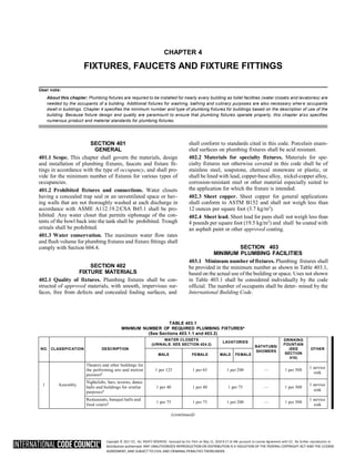

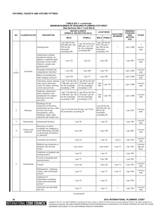
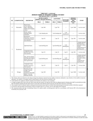
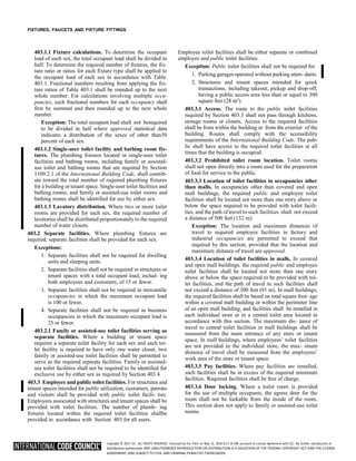


![Copyright © 2017 ICC. ALL RIGHTS RESERVED. Accessed by Eric Fitch on May 15, 2018 8:17:14 AM pursuant to License Agreement with ICC. No further reproduction or
distribution authorized. ANY UNAUTHORIZED REPRODUCTION OR DISTRIBUTION IS A VIOLATION OF THE FEDERAL COPYRIGHT ACT AND THE LICENSE
AGREEMENT, AND SUBJECT TO CIVIL AND CRIMINAL PENALTIES THEREUNDER.
FIXTURES, FAUCETS AND FIXTURE FITTINGS
SECTION 409
DISHWASHING MACHINES
409.1 Approval. Commercial dishwashing machines shall
conform to ASSE 1004 and NSF 3. Residential dishwashers
shall conform to NSF 184.
409.2 Water connection. The water supply to a dishwashing
machine shall be protected against backflow by an air gapthat
is integral with the machine or a backflow preventer shall be
installed in accordance with Section 608. Air gaps shall comply
with ASME A112.1.2 or A112.1.3.
409.3 Waste connection. The waste connection of a com-
mercial dishwashing machine shall comply with Section
802.1.6.
409.4 Residential dishwasher waste connection. The waste
connection of a residential dishwasher shall connect directly
to a wye branch fitting on the tailpiece of the kitchen sink,
directly to the dishwasher connection of a food waste dis- poser,
or through an air break to a standpipe. The waste lineof a
residential dishwasher shall rise and be securely fastened to the
underside of the sink rim or counter top.
SECTION 410
DRINKING FOUNTAINS
410.1 Approval. Drinking fountains shall conform to ASME
A112.19.1/CSA B45.2 or ASME A112.19.2/CSA B45.1 and
water coolers shall conform to ASHRAE 18. Drinking foun-
tains, water coolers and water dispensers shall conform to
NSF 61, Section 9. Electrically operated, refrigerated drink- ing
water coolers and water dispensers shall be listed and labeled
in accordance with UL 399.
410.2 Small occupancies. Drinking fountains shall not be
required for an occupant load of 15 or fewer.
[BE] 410.3 High and low drinking fountains. Where drink-
ing fountains are required, not fewer than two drinking foun-
tains shall be provided. One drinking fountain shall comply
with the requirements for people who use a wheelchair and one
drinking fountain shall comply with the requirements for
standing persons.
Exceptions:
1. A single drinking fountain with two separate spouts
that complies with the requirements for people who
use a wheelchair and standing persons shall be per-
mitted to be substituted for two separate drinking
fountains.
2. Where drinking fountains are primarily for chil-
dren’s use, the drinking fountains for people using
wheelchairs shall be permitted to comply with the
children’s provisions in ICC A117.1 and drinking
fountains for standing children shall be permitted to
provide the spout at 30 inches (762 mm) minimum
above the floor.
410.4 Substitution. Where restaurants provide drinking
water in a container free of charge, drinking fountains shall
not be required in those restaurants. In other occupancies where
drinking fountains are required, water dispensers shall
be permitted to be substituted for not more than 50 percent of
the required number of drinking fountains.
410.5 Prohibited location. Drinking fountains, water coolers
and water dispensers shall not be installed in public restrooms.
SECTION 411
EMERGENCY SHOWERS
AND EYEWASH STATIONS
411.1 Approval. Emergency showers and eyewash stations
shall conform to ISEA Z358.1.
411.2 Waste connection. Waste connections shall not be
required for emergency showers and eyewash stations.
411.3 Water supply. Where hot and cold water is supplied to
an emergencyshower or eyewash station, the temperature of the
water supply shall only be controlled by a temperature actuated
mixing valve complying with ASSE 1071.
SECTION 412
FAUCETS AND OTHER FIXTURE FITTINGS
412.1 Approval. Faucets and fixture fittings shall conform to
ASME A112.18.1/CSA B125.1. Faucets and fixture fittings
that supply drinking water for human ingestion shall conform
to the requirements of NSF 61, Section 9. Flexible water con-
nectors exposed to continuous pressure shall conform to the
requirements of Section 605.6.
412.1.1 Faucets and supply fittings. Faucets and supply
fittings shall conform to the water consumption require-
ments of Section 604.4.
412.1.2 Waste fittings. Waste fittings shall conform to
ASME A112.18.2/CSA B125.2, ASTM F409 or to one of
the standards listed in Tables 702.1 and 702.4 for above-
ground drainage and vent pipe and fittings.
412.2 Hand showers. Hand-held showers shall conform to
ASME A112.18.1/CSA B125.1. Hand-held showers shall pro-
vide backflow protection in accordance with ASME
A112.18.1/CSA B125.1 or shall be protected against backflow
by a device complying with ASME A112.18.3.
412.3 Individual shower valves. Individual shower and tub-
shower combination valves shall be balanced-pressure, ther-
mostatic or combination balanced-pressure/thermostatic valves
that conform to the requirements of ASSE 1016/ ASME
A112.1016/CSA B125.16 or ASME A112.18.1/CSA B125.1
and shall be installed at the point of use. Shower and tub-shower
combination valves required by this section shall be equipped
with a means to limit the maximum setting of the valve to 120°F
(49°C), which shall be field adjusted in accor- dance with the
manufacturer’s instructions. In-line thermo- static valves shall
not be utilized for compliance with this section.
412.4 Multiple (gang) showers. Multiple (gang) showers
supplied with a single-tempered water supply pipe shall have
the water supply for such showers controlled by an approved
automatic temperature control mixing valve that conforms to
ASSE 1069 or CSA B125.3, or each shower head shall be
individually controlled by a balanced-pressure, thermostatic](https://image.slidesharecdn.com/2018-ipc-international-plumbing-code-241129135518-3483e2e4/85/2018-IPC-International-Plumbing-Code-pdf-62-320.jpg)


![Copyright © 2017 ICC. ALL RIGHTS RESERVED. Accessed by Eric Fitch on May 15, 2018 8:17:14 AM pursuant to License Agreement with ICC. No further reproduction or
distribution authorized. ANY UNAUTHORIZED REPRODUCTION OR DISTRIBUTION IS A VIOLATION OF THE FEDERAL COPYRIGHT ACT AND THE LICENSE
AGREEMENT, AND SUBJECT TO CIVIL AND CRIMINAL PENALTIES THEREUNDER.
4
2
WATER HEATERS
504.7.1 Pan size and drain. The pan shall be not less than
11
/ inches (38 mm) in depth and shall be of sufficient size
and shape to receive all dripping or condensate from the
tank or water heater. The pan shall be drained by an indi-
rect waste pipe having a diameter of not less than 3
/ inch
(19 mm). Piping for safety pan drains shall be of those
materials listed in Table 605.4.
504.7.2 Pan drain termination. The pan drain shall extend
full size and terminate over a suitably located indi- rect waste
receptor or floor drain or extend to the exterior of the
building and terminate not less than 6 inches (152 mm) and
not more than 24 inches (610 mm) above the adjacent ground
surface. Where a pan drain was not previ- ously installed, a
pan drain shall not be required for areplacement water heater
installation.
SECTION 505
INSULATION
[E] 505.1 Unfired vessel insulation. Unfired hot water stor-
age tanks shall be insulated to R-12.5 (h • ft2
• ºF)/Btu (R-2.2
m2
• K/W).
2018 INTERNATIONAL PLUMBING CODE® 39](https://image.slidesharecdn.com/2018-ipc-international-plumbing-code-241129135518-3483e2e4/85/2018-IPC-International-Plumbing-Code-pdf-75-320.jpg)

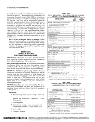

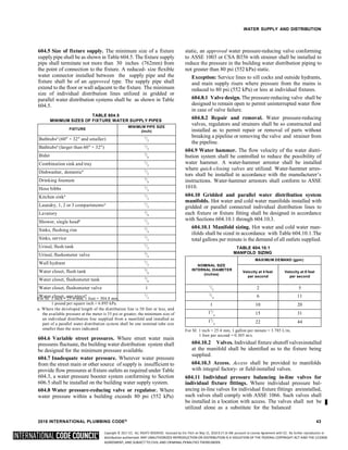
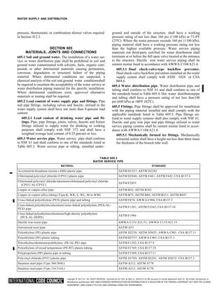

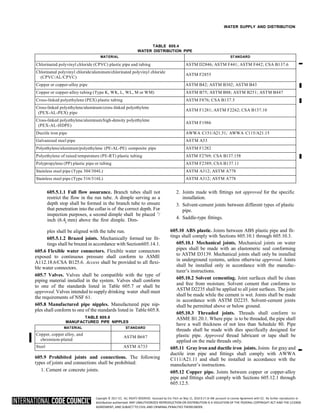


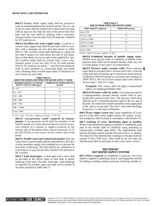

![Copyright © 2017 ICC. ALL RIGHTS RESERVED. Accessed by Eric Fitch on May 15, 2018 8:17:14 AM pursuant to License Agreement with ICC. No further reproduction or
distribution authorized. ANY UNAUTHORIZED REPRODUCTION OR DISTRIBUTION IS A VIOLATION OF THE FEDERAL COPYRIGHT ACT AND THE LICENSE
AGREEMENT, AND SUBJECT TO CIVIL AND CRIMINAL PENALTIES THEREUNDER.
WATER SUPPLY AND DISTRIBUTION
building maintenance. In nonresidential occupancies, hot
water shall be supplied for culinary purposes, cleansing,
laundry or building maintenance purposes. In nonresidential
occupancies, hot water or tempered water shall be supplied
for bathing and washing purposes.
607.1.1 Temperature limiting means. A thermostat con-
trol for a water heater shall not serve as the temperature
limiting means for the purposes of complying with the
requirements of this code for maximum allowable hot or
tempered water delivery temperature at fixtures.
607.1.2 Tempered water temperature control. Tem-
pered water shall be supplied through a water temperature
limiting device that conforms to ASSE 1070/ASME
A112.1070/CSA B125.70 and shall limit the tempered water
to not greater than 110ºF (43ºC). This provision shall not
supersede the requirement for protective shower valves in
accordance with Section 412.3.
607.2 Hot or tempered water supply to fixtures. The devel-
oped length of hot or tempered water piping, from the source of
hot water to the fixtures that require hot or tempered water, shall
not exceed 50 feet (15 240 mm). Recirculating system piping
and heat-traced piping shall be considered to be sources of hot
or tempered water.
607.2.1 Circulation systems and heat trace systems for
maintaining heated water temperature in distribution
systems. For Group R2, R3 and R4 occupancies that are
three stories or less in height above grade plane, the instal-
lation of heated water circulation and temperature mainte-
nance systems shall be in accordance with Section R403.5.1
of the International Energy Conservation Code. For other
than Group R2, R3 and R4 occupancies that are three stories
or less in height above grade plane, the instal- lation of
heated water circulation and heat trace systems shall be in
accordance with Section C404.6 of the Interna- tional
Energy Conservation Code.
607.2.1.1 Pump controls for hot water storage sys-
tems. The controls on pumps that circulate water between
a water heater and a storage tank for heated water shall
limit operation of the pump from heating cycle startup to
not greater than 5 minutes after the end of the cycle.
607.2.1.2 Demand recirculation controls for distri-
bution systems. A water distribution system having one
or more recirculation pumps that pump water froma
heated water supply pipe back to the heated water source
through a cold water supply pipe shall be a demand
recirculation water system. Pumps shall have controls
that comply with both of the following:
1. The control shall start the pump upon receiving a
signal from the action of a user of a fixture or
appliance, sensing the presence of a user of a fix-
ture, or sensing the flow of hot or tempered water
to a fixture fitting or appliance.
2. The control shall limit the temperature of the water
entering the cold water piping to 104°F (40°C).
607.2.2 Piping for recirculation systems having master
thermostatic valves. Where a thermostatic mixing valve
is used in a system with a hot water recirculating pump,
the hot water or tempered water return line shall be routed
to the cold water inlet pipe of the water heater and the cold
water inlet pipe or the hot water return connection of the
thermostatic mixing valve.
607.3 Thermal expansion control. Where a storage water
heater is supplied with cold water that passes through a check
valve, pressure reducing valve or backflow preventer, a ther-
mal expansion control device shall be connected to the water
heater cold water supply pipe at a point that is downstream of
all check valves, pressure reducing valves and backflow pre-
venters. Thermal expansion tanks shall be sized in accor- dance
with the tank manufacturer’s instructions and shall be sized
such that the pressure in the water distribution system shall not
exceed that required by Section 604.8.
607.4 Flow of hot water to fixtures. Fixture fittings, faucets
and diverters shall be installed and adjusted so that the flow
of hot water from the fittings corresponds to the left-hand
side of the fixture fitting.
Exception: Shower and tub/shower mixing valves con-
forming to ASSE 1016/ASME A112.1016/CSA B125.16
or ASME A112.18.1/CSA B125.1, where the flow of hot
water corresponds to the markings on the device.
[E] 607.5 Insulation of piping. For other than Group R2, R3
and R4 occupancies that are three stories or less in height above
grade plane, piping to the inlet of a water heater and piping
conveying water heated by a water heater shall beinsulated in
accordance with Section C404.4 of the Interna- tional Energy
Conservation Code. For Group R2, R3 and R4 occupancies that
are three stories or less in height above grade plane, piping to
the inlet of a water heater and piping conveying water heated
by a water heater shall be insulated in accordance with Section
R403.5.3 of the International Energy Conservation Code.
SECTION 608
PROTECTION OF POTABLE WATER SUPPLY
608.1 General. A potable water supply system shall be
designed, installed and maintained in such a manner so as to
prevent contamination from nonpotable liquids, solids or gases
being introduced into the potable water supply through cross
connections or any other piping connections to the sys- tem.
Backflow preventer applications shall conform to Table 608.1,
except as specifically stated in Sections 608.2 through
608.17.10.
608.2 Plumbing fixtures. The supply lines and fittings for
plumbing fixtures shall be installed so as to prevent backflow.
Plumbing fixture fittings shall provide backflow protection in
accordance with ASME A112.18.1/CSA B125.1.
608.3 Devices, appurtenances, appliances and apparatus.
Devices, appurtenances, appliances and apparatus intended to
serve some special function, such as sterilization, distillation,
processing, cooling, or storage of ice or foods, and that con-
nect to the water supply system, shall be provided with pro-
2018 INTERNATIONAL PLUMBING CODE® 51](https://image.slidesharecdn.com/2018-ipc-international-plumbing-code-241129135518-3483e2e4/85/2018-IPC-International-Plumbing-Code-pdf-93-320.jpg)
![Copyright © 2017 ICC. ALL RIGHTS RESERVED. Accessed by Eric Fitch on May 15, 2018 8:17:14 AM pursuant to License Agreement with ICC. No further reproduction or
distribution authorized. ANY UNAUTHORIZED REPRODUCTION OR DISTRIBUTION IS A VIOLATION OF THE FEDERAL COPYRIGHT ACT AND THE LICENSE
AGREEMENT, AND SUBJECT TO CIVIL AND CRIMINAL PENALTIES THEREUNDER.
WATER SUPPLY AND DISTRIBUTION
tection against backflow and contamination of the water supply
system.
608.3.1 Special equipment, water supply protection.
The water supply for hospital fixtures shall be protected
against backflow with a reduced pressure principle back-
flow prevention assembly, an atmospheric or spill-resis-tant
vacuum breaker assembly, or an air gap. Vacuum breakers
for bedpan washer hoses shall not be located less than 5 feet
(1524 mm) above the floor. Vacuum breakers for hose
connections in health care or laboratory areas shall be not
less than 6 feet (1829 mm) above the floor.
608.4 Potable water handling and treatment equipment.
Water pumps, filters, softeners, tanks and other appliances and
devices that handle or treat potable water to be suppliedto the
potable water distribution system shall be located to prevent
contamination from entering the appliances and devices.
Overflow, relief valve and waste discharge pipes from such
appliances and devices shall terminate through an air gap.
608.5 Water service piping. Water service piping shall be
protected in accordance with Sections 603.2 and 603.2.1.
608.6 Chemicals and other substances. Chemicals and other
substances that produce either toxic conditions, taste, odor or
discoloration in a potable water system shall not be introduced
into, or utilized in, such systems.
608.7 Cross connection control. Cross connections shall be
prohibited, except where approved backflow prevention
assemblies, backflow prevention devices or other means or
methods are installed to protect the potable water supply.
608.7.1 Private water supplies. Cross connections
between a private water supply and a potable public sup- ply
shall be prohibited.
608.8 Valves and outlets prohibited below grade. Potable
water outlets and combination stop-and-waste valves shall not
be installed underground or below grade. A freezeproof yard
hydrant hydrant that drains the riser into the ground shall be
considered as having a stop-and-waste valve below grade.
Exception: Freezeproof yard hydrants that drain the riser
into the ground shall be permitted to be installed, provided
that the potable water supply to such hydrants is protected in
accordance with Section 613.13.2 or 613.13.5, and the
hydrants and the piping from the backflow preventer to the
hydrant are identified in accordance with Section 608.9.
608.9 Identification of nonpotable water systems. Where
nonpotable water systems are installed, the piping conveying
the nonpotable water shall be identified either by color mark-
ing, metal tags or tape in accordance with Sections 608.9.1
through 608.9.2.3.
608.9.1 Signage required. Nonpotable water outlets, such
as hose connections, open ended pipes and faucets, shallbe
identified with signage that reads as follows: “Non-potable
water is utilized for [application name]. CAU- TION:
NONPOTABLE WATER – DO NOT DRINK.”The words
shall be legibly and indelibly printed on a tagor sign
constructed of corrosion-resistant waterproof mate- rial or
shall be indelibly printed on the fixture. The lettersof the
words shall be not less than 0.5 inch (12.7 mm) in
height and in colors in contrast to the background on which
they are applied. In addition to the required word- age, the
pictograph shown in Figure 608.9.1 shall appearon the
required signage.
FIGURE 608.9.1
PICTOGRAPH—DO NOT DRINK
608.9.2 Distribution pipe labeling and marking. Non-
potable distribution piping shall be purple in color andshall
be embossed, or integrally stamped or marked, with the
words: “CAUTION: NONPOTABLE WATER – DO NOT
DRINK” or the piping shall be installed with a pur- ple
identification tape or wrap. Pipe identification shallinclude
the contents of the piping system and an arrow indicating the
direction of flow. Hazardous piping systems shall also
contain information addressing the nature of the hazard. Pipe
identification shall be repeated at intervalsnot exceeding
25 feet (7620 mm) and at each point where the piping passes
through a wall, floor or roof. Lettering shall be readily
observable within the room or space where the piping is
located.
608.9.2.1 Color. The color of the pipe identificationshall
be discernable and consistent throughout the building.
The color purple shall be used to identify reclaimed, rain
and gray water distribution systems.
608.9.2.2 Lettering size. The size of the background
color field and lettering shall comply with Table
608.9.2.2.
TABLE 608.9.2.2
SIZE OF PIPE IDENTIFICATION
PIPE DIAMETER
(inches)
LENGTH BACKGROUND
COLOR FIELD
(inches)
SIZE OF LETTERS
(inches)
3
/ to 11
/
4 4 8 0.5
11
/ to 2
2
8 0.75
21
/ to 6
2 12 1.25
8 to 10 24 2.5
Over 10 32 3.5
For SI 1 inch = 25.4 mm.
52 2018 INTERNATIONAL PLUMBING CODE®](https://image.slidesharecdn.com/2018-ipc-international-plumbing-code-241129135518-3483e2e4/85/2018-IPC-International-Plumbing-Code-pdf-94-320.jpg)
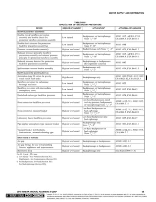
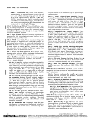
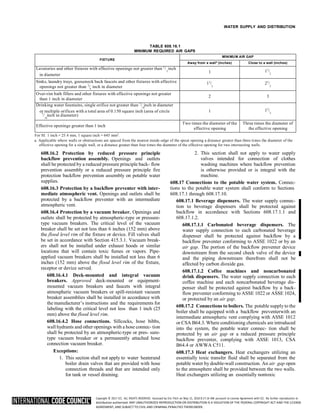

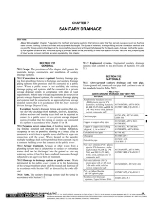
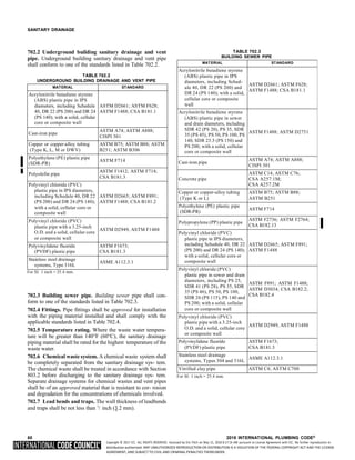


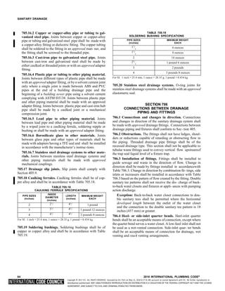
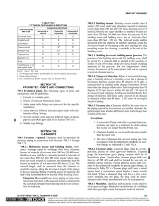
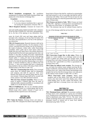

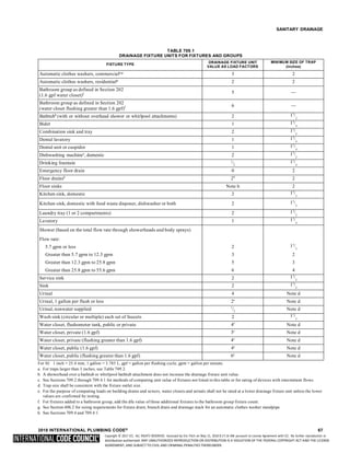
![Copyright © 2017 ICC. ALL RIGHTS RESERVED. Accessed by Eric Fitch on May 15, 2018 8:17:14 AM pursuant to License Agreement with ICC. No further reproduction or
distribution authorized. ANY UNAUTHORIZED REPRODUCTION OR DISTRIBUTION IS A VIOLATION OF THE FEDERAL COPYRIGHT ACT AND THE LICENSE
AGREEMENT, AND SUBJECT TO CIVIL AND CRIMINAL PENALTIES THEREUNDER.
SANITARY DRAINAGE
TABLE 710.1(1)
BUILDING DRAINS AND SEWERS
DIAMETER OF
PIPE (inches)
MAXIMUM NUMBER OF DRAINAGE FIXTURE UNITS
CONNECTED TO ANY PORTION OF THE BUILDING
DRAIN OR THE BUILDING SEWER, INCLUDING
BRANCHES OF THE BUILDING DRAINa
Slope per foot
1
/ inch
16
1
/ inch
8
1
/ inch
4
1
/ inch
2
11
/
4 — — 1 1
11
/
2 — — 3 3
2 — — 21 26
21
/
2 — — 24 31
3 — 36 42 50
4 — 180 216 250
5 — 390 480 575
6 — 700 840 1,000
8 1,400 1,600 1,920 2,300
10 2,500 2,900 3,500 4,200
12 3,900 4,600 5,600 6,700
15 7,000 8,300 10,000 12,000
For SI: 1 inch = 25.4 mm, 1 inch per foot = 83.3 mm/m.
a. The minimum size of any building drain serving a water closet shall be 3
inches.
TABLE 710.1(2)
HORIZONTAL FIXTURE BRANCHES AND STACKSa
DIAMETER OF
PIPE (inches)
MAXIMUM NUMBER OF DRAINAGE FIXTURE UNITS (dfu)
Total for
horizontal
branch
Stacksb
Total
discharge
into one
branch
interval
Total for stack
of three
branch
Intervals or
less
Total for stack
greater than
three branch
intervals
11
/2 3 2 4 8
2 6 6 10 24
21
/2 12 9 20 42
3 20 20 48 72
4 160 90 240 500
5 360 200 540 1,100
6 620 350 960 1,900
8 1,400 600 2,200 3,600
10 2,500 1,000 3,800 5,600
12 3,900 1,500 6,000 8,400
15 7,000 Note c Note c Note c
For SI: 1 inch = 25.4 mm.
a. Does not include branches of the building drain. Refer to Table 710.1(1).
b. Stacks shall be sized based on the total accumulated connected load at
each story or branch interval. As the total accumulated connected load
decreases, stacks are permitted to be reduced in size. Stack diameters shall
not be reduced to less than one-half of the diameter of the largest stack
size required.
c. Sizing load based on design criteria.
710.1.1 Horizontal stack offsets. Horizontal stack offsets
shall be sized as required for building drains in accordance
with Table 710.1(1), except as required by Section 711.3.
710.1.2 Vertical stack offsets. Vertical stack offsets shall
be sized as required for straight stacks in accordance with
Table 710.1(2), except where required to be sized as a
building drain in accordance with Section 711.1.1.
710.2 Future fixtures. Where provision is made for the future
installation of fixtures, those provided for shall be con- sidered
in determining the required sizes of drain pipes.
SECTION 711
OFFSETS IN DRAINAGE PIPING IN
BUILDINGS OF FIVE STORIES OR MORE
711.1 Horizontal branch connections above or below ver-
tical stack offsets. If a horizontal branch connects to thestack
within 2 feet (610 mm) above or below a vertical stack offset,
and the offset is located more than four branch inter- vals below
the top of the stack, the offset shall be vented in accordance with
Section 907.
711.1.1 Omission of vents for vertical stack offsets.
Vents for vertical offsets required by Section 711.1 shall not
be required where the stack and its offset are sized as a
building drain [see Table 710.1(1)].
711.2 Horizontal stack offsets. A stack with a horizontal
offset located more than four branch intervals below the top
of the stack shall be vented in accordance with Section 907and
sized as follows:
1. The portion of the stack above the offset shall be sized
as for a vertical stack based on the total number of
drainage fixture units above the offset.
2. The offset shall be sized in accordance with Section
710.1.1.
3. The portion of the stack below the offset shall be sized
as for the offset or based on the total number of drain-
age fixture units on the entire stack, whichever is larger
[see Table 710.1(2), Column 5].
711.2.1 Omission of vents for horizontal stack offsets.
Vents for horizontal stack offsets required by Section
711.2 shall not be required where the stack and its offsetare
one pipe size larger than required for a building drain [see
Table 710.1(1)] and the entire stack and offset are not less in
cross-sectional area than that required for a straight stack
plus the area of an offset vent as provided for in Sec- tion
907.
711.3 Offsets below lowest branch. Where a vertical offset
occurs in a soil or waste stack below the lowest horizontal
branch, a change in diameter of the stack because of the off- set
shall not be required. If a horizontal offset occurs in a soil or
waste stack below the lowest horizontal branch, the required
diameter of the offset and the stack below it shall be determined
as for a building drain in accordance with Table 710.1(1).
SECTION 712
SUMPS AND EJECTORS
712.1 Building subdrains. Building subdrains that cannot be
discharged to the sewer by gravity flow shall be discharged into
a tightly covered and vented sump from which the liquid shall
be lifted and discharged into the building gravity drain- age
system by automatic pumping equipment or otherapproved
method. In other than existing structures, the sump](https://image.slidesharecdn.com/2018-ipc-international-plumbing-code-241129135518-3483e2e4/85/2018-IPC-International-Plumbing-Code-pdf-114-320.jpg)


![Copyright © 2017 ICC. ALL RIGHTS RESERVED. Accessed by Eric Fitch on May 15, 2018 8:17:14 AM pursuant to License Agreement with ICC. No further reproduction or
distribution authorized. ANY UNAUTHORIZED REPRODUCTION OR DISTRIBUTION IS A VIOLATION OF THE FEDERAL COPYRIGHT ACT AND THE LICENSE
AGREEMENT, AND SUBJECT TO CIVIL AND CRIMINAL PENALTIES THEREUNDER.
CHAPTER 9
VENTS
User note:
About this chapter: Chapter 9 regulates connection locations, various venting system arrangements and the sizing of piping for vent sys -
tems. The proper operation of a gravity flow drainage system (Chapter 7) depends on maintaining an air path throughout the system to pre-
vent waste and odor “blow back” into fixtures and siphoning of the trap seal in fixture traps (Chapter 10).
SECTION 901
GENERAL
901.1 Scope. The provisions of this chapter shall govern the
materials, design, construction and installation of vent sys-
tems.
901.2 Trap seal protection. The plumbing system shall be
provided with a system of vent piping that will permit the
admission or emission of air so that the seal of any fixture trap
shall not be subjected to a pressure differential of more than 1
inch of water column (249 Pa).
901.2.1 Venting required. Traps and trapped fixtures
shall be vented in accordance with one of the venting
methods specified in this chapter.
901.3 Chemical waste vent systems. The vent system for a
chemical waste system shall be independent of the sanitary vent
system and shall terminate separately through the roof to the
outdoors or to an air admittance valve that complies with ASSE
1049. Air admittance valves for chemical waste sys- tems shall
be constructed of materials approved in accor- dance with
Section 702.5 and shall be tested for chemical resistance in
accordance with ASTM F1412.
901.4 Use limitations. The plumbing vent system shall notbe
utilized for purposes other than the venting of the plumb- ing
system.
901.5 Tests. The vent system shall be tested in accordance with
Section 312.
901.6 Engineered systems. Engineered venting systemsshall
conform to the provisions of Section 919.
SECTION 902
MATERIALS
902.1 Vents. The materials and methods utilized for the con-
struction and installation of venting systems shall comply with
the applicable provisions of Section 702.
902.2 Sheet copper. Sheet copper for vent pipe flashings shall
conform to ASTM B152 and shall weigh not less than 8 ounces
per square foot (2.5 kg/m2
).
902.3 Sheet lead. Sheet lead for vent pipe flashings shallweigh
not less than 3 pounds per square foot (15 kg/m2
) for
field-constructed flashings and not less than 21
/ pounds per
SECTION 903
VENT TERMINALS
903.1 Roof extension. Open vent pipes that extend through a
roof shall be terminated not less than [NUMBER] inches (mm)
above the roof. Where a roof is to be used for assembly or as
a promenade, observation deck, sunbathing deck or similar
purposes, open vent pipes shall terminate not less than 7 feet
(2134 mm) above the roof.
903.2 Frost closure. Where the 97.5-percent value for out-
door design temperature is 0°F (-18°C) or less, vent exten- sions
through a roof or wall shall be not less than 3 inches (76 mm)
in diameter. Any increase in the size of the vent shall be made
not less than 1 foot (305 mm) inside the thermal enve- lope of
the building.
903.3 Flashings. The juncture of each vent pipe with the roof
line shall be made water tight by an approved flashing.
903.4 Prohibited use. A vent terminal shall not be used for any
purpose other than a vent terminal.
903.5 Location of vent terminal. An open vent terminal from
a drainage system shall not be located directly beneath any
door, openable window, or other air intake opening of the
building or of an adjacent building, and anysuch vent termi- nal
shall not be within 10 feet (3048 mm) horizontally of such an
opening unless it is 3 feet (914 mm) or more above the top of
such opening.
903.6 Extension through the wall. Vent terminals extending
through the wall shall terminate at a point not less than 10 feet
(3048 mm) from a lot line and not less than 10 feet (3048 mm)
above average ground level. Vent terminals shall not terminate
under the overhang of a structure with soffit vents. Side wall
vent terminals shall be protected to prevent birds or rodents
from entering or blocking the vent opening.
903.7 Extension outside a structure. In climates where the
97.5-percent value for outside design temperature is less than
0°F (-18°C), vent pipes installed on the exterior of the struc-
ture shall be protected against freezing by insulation, heat or
both.
SECTION 904
OUTDOOR VENT EXTENSIONS
2
2 904.1 Required vent extension. The vent system serving
square foot (12 kg/m ) for prefabricated flashings. each building drain shall have not less than one vent pipe that
extends to the outdoors.](https://image.slidesharecdn.com/2018-ipc-international-plumbing-code-241129135518-3483e2e4/85/2018-IPC-International-Plumbing-Code-pdf-123-320.jpg)

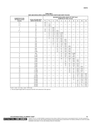
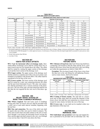

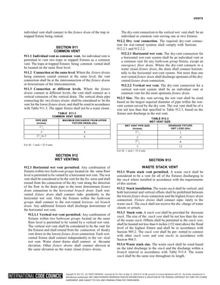

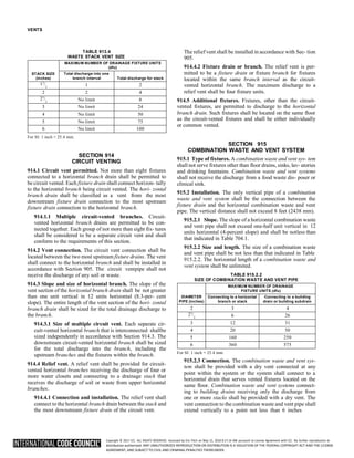


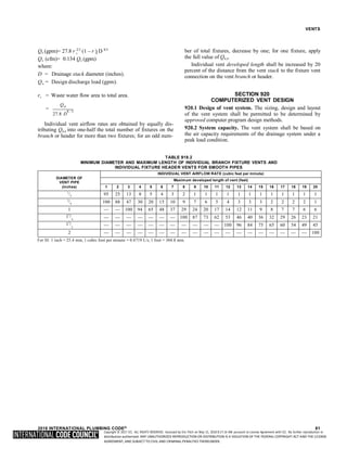

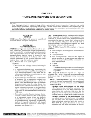

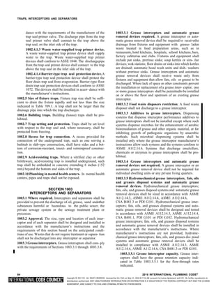
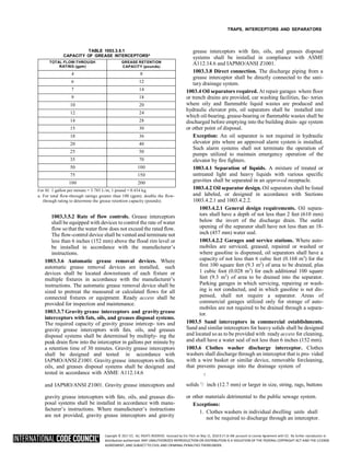
![Copyright © 2017 ICC. ALL RIGHTS RESERVED. Accessed by Eric Fitch on May 15, 2018 8:17:14 AM pursuant to License Agreement with ICC. No further reproduction or
distribution authorized. ANY UNAUTHORIZED REPRODUCTION OR DISTRIBUTION IS A VIOLATION OF THE FEDERAL COPYRIGHT ACT AND THE LICENSE
AGREEMENT, AND SUBJECT TO CIVIL AND CRIMINAL PENALTIES THEREUNDER.
CHAPTER 11
STORM DRAINAGE
User note:
About this chapter: Rainfall onto buildings must be removed and directed to a location that can accommodate storm water. Chapter 11 spec- ifies
the design rainfall event for the geographic area and provides sizing methods for piping and gutter systems to convey the storm water away
from the building. Included in this chapter are regulations for piping materials and subsoil drainage systems.
SECTION 1101
GENERAL
1101.1 Scope. The provisions of this chapter shall govern the
materials, design, construction and installation of storm
drainage.
1101.2 Disposal. Rainwater from roofs and storm water from
paved areas, yards, courts and courtyards shall drain to an
approved place of disposal. For one- and two-family dwell-
ings, and where approved, storm water is permitted to dis-
charge onto flat areas, such as streets or lawns, provided that
the storm water flows away from the building.
1101.3 Prohibited drainage. Storm water shall not be drained
into sewers intended for sewage only.
1101.4 Tests. The conductors and the building storm drain
shall be tested in accordance with Section 312.
1101.5 Change in size. The size of a drainage pipe shall not be
reduced in the direction of flow.
1101.6 Fittings and connections. Connections and changes
in direction of the storm drainage system shall be made with
approved drainage-type fittings in accordance with Table
706.3. The fittings shall not obstruct or retard flow in the sys-
tem.
[BS] 1101.7 Roof design. Roofs shall be designed for the
maximum possible depth of water that will pond thereon as
determined by the relative levels of roof deck and overflow
weirs, scuppers, edges or serviceable drains in combination
with the deflected structural elements. In determining the
maximum possible depth of water, all primary roof drainage
means shall be assumed to be blocked. The maximum possi- ble
depth of water on the roof shall include the height of the water
required above the inlet of the secondary roof drainage means
to achieve the required flow rate of the secondary drainage
means to accommodate the design rainfall rate as required by
Section 1106.
1101.8 Cleanouts required. Cleanouts shall be installed in the
storm drainage system and shall comply with the provi- sions
of this code for sanitary drainage pipe cleanouts.
Exception: Subsurface drainage system.
1101.9 Backwater valves. Storm drainage systems shall be
provided with backwater valves as required for sanitary
drainage systems in accordance with Section 715.
SECTION 1102
MATERIALS
1102.1 General. The materials and methods utilized for the
construction and installation of storm drainage systems shall
comply with this section and the applicable provisions of
Chapter 7.
1102.2 Inside storm drainage conductors. Inside storm
drainage conductors installed above ground shall conform to
one of the standards listed in Table 702.1.
1102.3 Underground building storm drain pipe. Under-
ground building storm drain pipe shall conform to one of the
standards listed in Table 702.2.
1102.4 Building storm sewer pipe. Building storm sewer pipe
shall conform to one of the standards listed in Table 1102.4.
TABLE 1102.4
BUILDING STORM SEWER PIPE
MATERIAL STANDARD
Acrylonitrile butadiene styrene
(ABS) plastic pipe in IPS
diameters, including Schedule 40,
DR 22 (PS 200) and DR 24 (PS
140); with a solid, cellular core or
composite wall.
ASTM D2661; ASTM F628;
ASTM F1488; CSA B181.1;
CSA B182.1
Cast-iron pipe
ASTM A74; ASTM A888;
CISPI 301
Concrete pipe
ASTM C14; ASTM C76;
CSA A257.1M; CSA A257.2M
Copper or copper-alloy tubing
(Type K, L, M or DWV)
ASTM B75; ASTM B88;
ASTM B251; ASTM B306
Polyethylene (PE) plastic pipe
ASTM F667;
ASTM F2306/F2306M;
ASTM F2648/F2648M
Polypropylene (PP) pipe ASTM F2881; CSA B182.13
Polyvinyl chloride (PVC) plastic
pipe (Type DWV, SDR26,
SDR35, SDR41, PS50 or PS100)
in IPS diameters, including
Schedule 40, DR 22 (PS 200) and
DR 24 (PS 140); with a solid,
cellular core or composite wall.
ASTM D2665; ASTM D3034;
ASTM F891; ASTM F1488;
CSA B182.4;
CSA B181.2; CSA B182.2
Vitrified clay pipe ASTM C4; ASTM C700
Stainless steel drainage systems,
Type 316L
ASME A112.3.1](https://image.slidesharecdn.com/2018-ipc-international-plumbing-code-241129135518-3483e2e4/85/2018-IPC-International-Plumbing-Code-pdf-144-320.jpg)
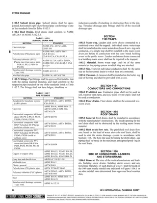
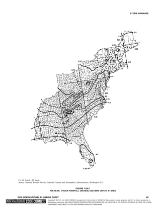
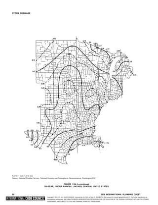
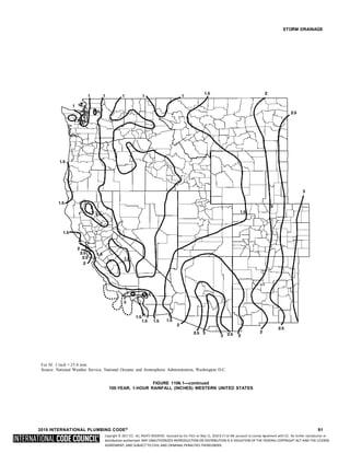
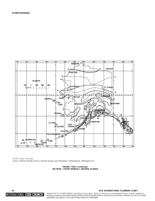
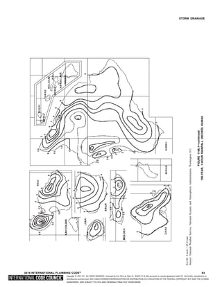
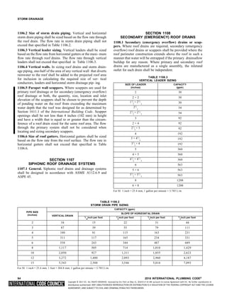
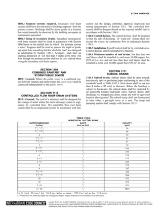

![Copyright © 2017 ICC. ALL RIGHTS RESERVED. Accessed by Eric Fitch on May 15, 2018 8:17:14 AM pursuant to License Agreement with ICC. No further reproduction or
distribution authorized. ANY UNAUTHORIZED REPRODUCTION OR DISTRIBUTION IS A VIOLATION OF THE FEDERAL COPYRIGHT ACT AND THE LICENSE
AGREEMENT, AND SUBJECT TO CIVIL AND CRIMINAL PENALTIES THEREUNDER.
CHAPTER 12
SPECIAL PIPING AND STORAGE SYSTEMS
User note:
About this chapter: Chapter 12 specifies the standards covering the installation of nonflammable medical gas piping systems and nonmedi-
cal oxygen piping systems.
SECTION 1201
GENERAL
1201.1 Scope. The provisions of this chapter shall govern the
design and installation of piping and storage systems for non-
flammable medical gas systems and nonmedical oxygen sys-
tems. All maintenance and operations of such systems shall
be in accordance with the International Fire Code.
SECTION 1202
MEDICAL GASES
[F] 1202.1 Nonflammable medical gases. Nonflammable
medical gas systems, inhalation anesthetic systems and vac-
uum piping systems shall be designed and installed in accor-
dance with NFPA 99.
Exceptions:
1. This section shall not apply to portable systems or
cylinder storage.
2. Vacuum system exhaust terminations shall comply
with the International Mechanical Code.
SECTION 1203
OXYGEN SYSTEMS
[F] 1203.1 Design and installation. Nonmedical oxygen sys-
tems shall be designed and installed in accordance with NFPA
55 and NFPA 51.
2018 INTERNATIONAL PLUMBING CODE® 97](https://image.slidesharecdn.com/2018-ipc-international-plumbing-code-241129135518-3483e2e4/85/2018-IPC-International-Plumbing-Code-pdf-156-320.jpg)

![Copyright © 2017 ICC. ALL RIGHTS RESERVED. Accessed by Eric Fitch on May 15, 2018 8:17:14 AM pursuant to License Agreement with ICC. No further reproduction or
distribution authorized. ANY UNAUTHORIZED REPRODUCTION OR DISTRIBUTION IS A VIOLATION OF THE FEDERAL COPYRIGHT ACT AND THE LICENSE
AGREEMENT, AND SUBJECT TO CIVIL AND CRIMINAL PENALTIES THEREUNDER.
CHAPTER 13
NONPOTABLE WATER SYSTEMS
User note:
About this chapter: Storm water and some liquid waste from a building can be a source of nonpotable water that can be used to reduce the
volume of potable water supplied to the building. Chapter 13 provides the requirements for storage, treatment and distribution of this resource. This
chapter also regulates the piping systems for reclaimed water supplied by a wastewater treatment facility.
SECTION 1301
GENERAL
1301.1 Scope. The provisions of Chapter 13 shall govern the
materials, design, construction and installation of systems for
the collection, storage, treatment and distribution of nonpota-
ble water. The use and application of nonpotable water shall
comply with laws, rules and ordinances applicable in the
jurisdiction.
1301.2 Water quality. Nonpotable water for each end use
application shall meet the minimum water quality require-
ments as established for the intended application by the laws,
rules and ordinances applicable in the jurisdiction. Where
nonpotable water from different sources is combined in a sys-
tem, the system shall comply with the most stringent of the
requirements of this code that are applicable to such sources.
1301.2.1 Residual disinfectants. Where chlorine is used for
disinfection, the nonpotable water shall contain not more
than 4 ppm (4mg/L) of chloramines or free chlorine when
tested in accordance with ASTM D1253. Where ozone is
used for disinfection, the nonpotable water shall not contain
gas bubbles having elevated levels of ozone at the point of
use.
Exception: Reclaimed water sources shall not berequired
to comply with these requirements.
1301.2.2 Filtration required. Nonpotable water utilizedfor
water closet and urinal flushing applications shall be filtered
by a 100-micron or finer filter.
Exception: Reclaimed water sources shall not berequired
to comply with these requirements.
1301.3 Signage required. Nonpotable water outlets such as
hose connections, open ended pipes and faucets shall be iden-
tified at the point of use for each outlet with signage that
reads as follows: “Nonpotable water is utilized for [applica- tion
name]. CAUTION: NONPOTABLE WATER – DO
NOT DRINK.” The words shall be legibly and indelibly printed
on a tag or sign constructed of corrosion-resistant waterproof
material or shall be indelibly printed on the fix- ture. The letters
of the words shall be not less than 0.5 inch (12.7 mm) in height
and in colors in contrast to the back- ground on which they are
applied. In addition to the required wordage, the pictograph
shown in Figure 1301.3 shall appear on the signage required by
this section.
1301.4 Permits. Permits shall be required for the construc- tion,
installation, alteration and repair of nonpotable watersystems.
Construction documents, engineering calculations,
diagrams and other such data pertaining to the nonpotable water
system shall be submitted with each permit application.
1301.5 Potable water connections. Where a potable system
is connected to a nonpotable water system, the potable water
supply shall be protected against backflow in accordance with
Section 608.
1301.6 Components and materials. Piping, plumbing com-
ponents and materials used in collection and conveyance sys-
tems shall be of material approved by the manufacturer forthe
intended application.
1301.7 Insect and vermin control. The system shall be pro-
tected to prevent the entrance of insects and vermin into stor-
age tanks and piping systems. Screen materials shall be
compatible with contacting system components and shall not
accelerate the corrosion of system components.
1301.8 Freeze protection. Where sustained freezing tem-
peratures occur, provisions shall be made to keep storage tanks
and the related piping from freezing.
1301.9 Nonpotable water storage tanks. Nonpotable water
storage tanks shall comply with Sections 1301.9.1 through
1301.9.10.
FIGURE 1301.3
PICTOGRAPH—DO NOT DRINK
➡](https://image.slidesharecdn.com/2018-ipc-international-plumbing-code-241129135518-3483e2e4/85/2018-IPC-International-Plumbing-Code-pdf-158-320.jpg)


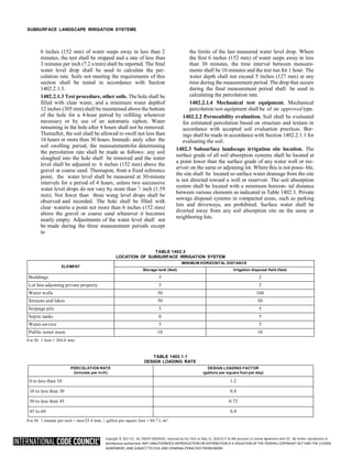


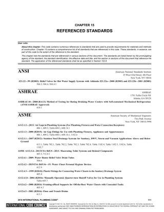
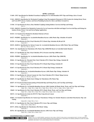
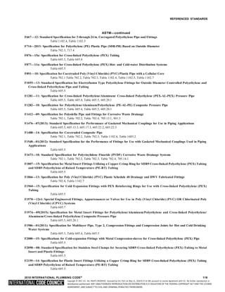
![Copyright © 2017 ICC. ALL RIGHTS RESERVED. Accessed by Eric Fitch on May 15, 2018 8:17:14 AM pursuant to License Agreement with ICC. No further reproduction or
distribution authorized. ANY UNAUTHORIZED REPRODUCTION OR DISTRIBUTION IS A VIOLATION OF THE FEDERAL COPYRIGHT ACT AND THE LICENSE
AGREEMENT, AND SUBJECT TO CIVIL AND CRIMINAL PENALTIES THEREUNDER.
REFERENCED STANDARDS
ASTM—continued
F2262—09: Specification for Cross-linked Polyethylene/Aluminum/Cross-linked Polyethylene Tubing OD Controlled SDR9
Table 605.3, Table 605.4
F2306/F2306M—14e1: 12'' to 60'' Annular Corrugated Profile-wall Polyethylene (PE) Pipe and Fittings for Gravity Flow Storm
Sewer and Subsurface Drainage Applications
Table 1102.4, Table 1102.7
F2389—15: Specification for Pressure-rated Polypropylene (PP) Piping Systems
Table 605.3, Table 605.4, Table 605.5, Table 605.7, 605.19.1
F2434—14: Standard Specification for Plastic Insert Fittings Utilizing a Copper Crimp Ring for SDR9 Cross-linked Polyethylene
(PEX) Tubing and SDR9 Cross-linked Polyethylene/Aluminum/ Cross-linked Polyethylene (PEX AL-PEX) Tubing
Table 605.5
F2648/F2648M—13: Standard Specification for 2 to 60 inch [50 to 1500 mm] Annular Corrugated Profile Wall Polyethylene (PE) Pipe
and Fittings for Land Drainage Applications
Table 1102.4
F2735—09: Standard Specification for Plastic Insert Fittings for SDR9 Cross-linked Polyethylene (PEX) and Polyethylene of Raised
Temperature (PE-RT) Tubing
Table 605.5
F2736—13e1: Standard Specification for 6 to 30 in. [152 to 762 mm] Polypropylene (PP) Corrugated Single Wall Pipe and Double
Wall Pipe
Table 702.3
F2764/F2764M—11ae2: Standard Specification for 30 to 60 in. [750 to 1500 mm] Polypropylene (PP) Triple Wall Pipe and Fittings for
Non-pressure Sanitary Sewer Applications
Table 702.3
F2769—14: Polyethylene or Raised Temperature (PE-RT) Plastic Hot- and Cold-water Tubing and Distribution Systems
Table 605.3, Table 605.4, Table 605.5
F2831—12: Standard Practice for Internal Non Structural Epoxy Barrier Coating Material Used in Rehabilitation of Metallic
Pressurized Piping Systems
601.5
F2855—12: Standard Specification for Chlorinated Poly (Vinyl Chloride)/Aluminum/Chlorinated Poly (Vinyl Chloride) (CPVC/AL/
CPVC) Composite Pressure Tubing
Table 605.3, Table 605.4
F2881—11: Standard Specification for 12 to 60 in. [300 to 1500 mm] Polypropylene (PP) Dual Wall Pipe and Fittings for Non-pressure
Storm Sewer Applications
Table 1102.4
AWS American Welding Society
8669 NW 36 Street, #130
Miami, FL 33166
A5.8M/A5.8—2011: Specifications for Filler Metals for Brazing and Braze Welding
605.12.1, 605.13.1, 705.5.1, 705.6.1
AWWA American Water Works Association
6666 West Quincy Avenue
Denver, CO 80235
C104/A21.4—13: Cement-mortar Lining for Ductile-iron Pipe and Fittings
605.3, 605.5
C110/A21.10—12: Ductile-iron and Gray-iron Fittings
Table 605.5, Table 702.4, Table 1102.7
C111/A21.11—12: Rubber-gasket Joints for Ductile-iron Pressure Pipe and Fittings
605.11
C115/A21.15—11: Flanged Ductile-iron Pipe with Ductile-iron or Gray-iron Threaded Flanges
Table 605.3, Table 605.4
C151/A21.51—09: Ductile-iron Pipe, Centrifugally Cast for Water
Table 605.3, Table 605.4
120 2018 INTERNATIONAL PLUMBING CODE®](https://image.slidesharecdn.com/2018-ipc-international-plumbing-code-241129135518-3483e2e4/85/2018-IPC-International-Plumbing-Code-pdf-184-320.jpg)


![Copyright © 2017 ICC. ALL RIGHTS RESERVED. Accessed by Eric Fitch on May 15, 2018 8:17:14 AM pursuant to License Agreement with ICC. No further reproduction or
distribution authorized. ANY UNAUTHORIZED REPRODUCTION OR DISTRIBUTION IS A VIOLATION OF THE FEDERAL COPYRIGHT ACT AND THE LICENSE
AGREEMENT, AND SUBJECT TO CIVIL AND CRIMINAL PENALTIES THEREUNDER.
APPENDIX C
STRUCTURAL SAFETY
The provisions contained in this appendix are not mandatory unless specifically referenced in the adopting ordinance.
User note:
About this appendix: The installation of plumbing systems frequently requires piping to pass through building framing members. Appendix C
provides the regulations for limits on the sizes and locations of holes that can be drilled or punched in various types of framing members.
SECTION C101
CUTTING, NOTCHING AND
or notched. Holes in webs of nonstructural cold-formed steel
wall studs shall be permitted along the centerline of the web
BORING IN WOOD MEMBERS of the framing member, shall not exceed 11
/ inches (38 mm)
[BS] C101.1 Joist notching. Notches on the ends of joists shall
not exceed one-fourth the joist depth. Holes bored in joists shall
not be within 2 inches (51 mm) of the top or bot- tom of the
joist, and the diameter of any such hole shall not exceed one-
third the depth of the joist. Notches in the top or bottom of joists
shall not exceed one-sixth the depth and shall not be located in
the middle third of the span.
[BS] C101.2 Stud cutting and notching. In exterior wallsand
bearing partitions, any wood stud is permitted to be cut or
notched to a depth not exceeding 25 percent of its width. Cut-
ting or notching of studs to a depth not greater than 40 per- cent
of the width of the stud is permitted in nonbearing partitions
supporting no loads other than the weight of the partition.
[BS] C101.3 Bored holes. The diameter of bored holes in wood
studs shall not exceed 40 percent of the stud depth. The
diameter of bored holes in wood studs shall not exceed 60
percent of the stud depth in nonbearing partitions. The diame-
ter of bored holes in wood studs shall not exceed 60 percent
of the stud depth in any wall where each stud is doubled, pro-
vided that not more than two such successive doubled studsare
so bored. The edge of the bored hole shall not be closer
in width or 4 inches (102 mm) in length, and the holes shall
not be spaced less than 24 inches (610 mm) center to center
from another hole or less than 10 inches (254 mm) from the
bearing end.
than 5
/ inch (15.9 mm) to the edge of the stud. Bored holes
shall be not located at the same section of stud as a cut or notch.
[BS] C101.4 Cutting, notching and boring holes in struc-
tural steel framing. The cutting, notching and boring of holes
in structural steel framing members shall be as pre-scribed by
the registered design professional.
[BS] C101.5 Cutting, notching and boring holes in cold-
formed steel framing. Flanges and lips of load-bearing cold-
formed steel framing members shall not be cut or notched.
Holes in webs of load-bearing cold-formed steel framing
members shall be permitted along the centerline of the web of
the framing member and shall not exceed the dimensional
limitations, penetration spacing or minimum hole edge dis-
tance as prescribed by the registered design professional. Cut-
ting, notching and boring holes of steel floor/roof decking shall
be as prescribed by the registered design professional.
[BS] C101.6 Cutting, notching and boring holes in non-
structural cold-formed steel wall framing. Flanges and lips
of nonstructural cold-formed steel wall studs shall not be cut
2
8](https://image.slidesharecdn.com/2018-ipc-international-plumbing-code-241129135518-3483e2e4/85/2018-IPC-International-Plumbing-Code-pdf-196-320.jpg)


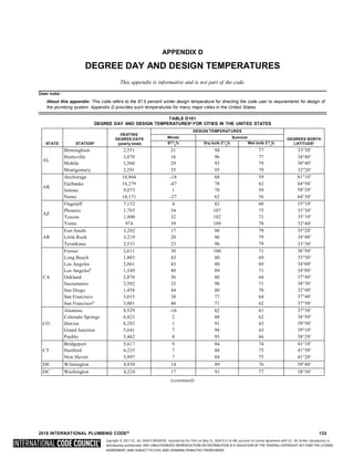
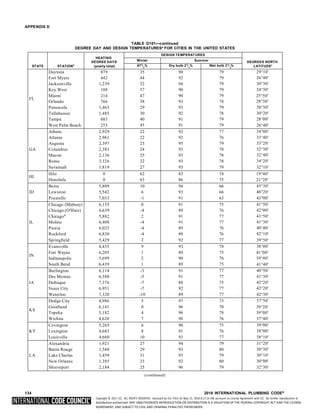
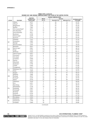
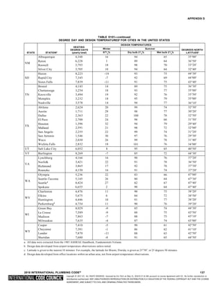

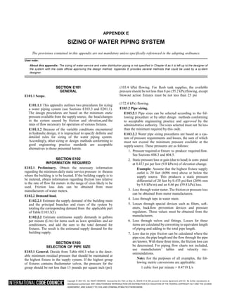

![Copyright © 2017 ICC. ALL RIGHTS RESERVED. Accessed by Eric Fitch on May 15, 2018 8:17:14 AM pursuant to License Agreement with ICC. No further reproduction or
distribution authorized. ANY UNAUTHORIZED REPRODUCTION OR DISTRIBUTION IS A VIOLATION OF THE FEDERAL COPYRIGHT ACT AND THE LICENSE
AGREEMENT, AND SUBJECT TO CIVIL AND CRIMINAL PENALTIES THEREUNDER.
APPENDIX E
1 square foot = 0.0929 m2
1 degree = 0.0175 rad
1 pound per square inch = 6.895 kPa
1 inch = 25.4 mm
1 foot = 304.8 mm
1 gallon per minute = 3.785 L/m
E103.3 Segmented loss method. The size of water service
mains, branch mains and risers by the segmented loss method
must be determined according to water supply demand [gpm
(L/m)], available water pressure [psi (kPa)] and friction loss
caused by the water meter and developed length of pipe [feet
(m)], including equivalent length of fittings. This design pro-
cedure is based on the following parameters:
• Calculates the friction loss through each length of the pipe.
• Based on a system of pressure losses, the sum of which
must not exceed the minimum pressure available at the
street main or other source of supply.
• Pipe sizing based on estimated peak demand, total pressure
losses caused by difference in elevation, equipment,
developed length and pressure required at most remote
fixture, loss through taps in water main,losses through
fittings, filters, backflow prevention devices, valves and
pipe friction.
Because of the variable conditions encountered in hydrau-
lic design, it is impractical to specify definite and detailed rules
for sizing of the water piping system. Current sizing methods
do not address the differences in the probability ofuse and
flow characteristics of fixtures between types of occupancies.
Creating an exact model of predicting the demand for a
building is impossible and final studies assess- ing the impact
of water conservation on demand are not yet complete. The
following steps are necessary for the seg- mented loss method.
1. Preliminary. Obtain the necessary information regard-
ing the minimum daily static service pressure in thearea
where the building is to be located. If the building supply
is to be metered, obtain information regarding friction
loss relative to the rate of flow for meters in the range of
sizes to be used. Friction loss data can beobtained from
manufacturers of water meters. It is essential that enough
pressure be available to overcome all system losses
caused by friction and elevation sothat plumbing
fixtures operate properly. Section 604.6 requires the
water distribution system to be designed for the
minimum pressure available taking into consid- eration
pressure fluctuations. The lowest pressure must be
selected to guarantee a continuous, adequate supplyof
water. The lowest pressure in the public main usu- ally
occurs in the summer because of lawn sprinkling and
supplying water for air-conditioning cooling tow- ers.
Future demands placed on the public main as a result of
large growth or expansion should be consid- ered. The
available pressure will decrease as additional loads are
placed on the public system.
2. Demand load. Estimate the supply demand of the
building main and the principal branches and risers of
the system by totaling the corresponding demand from
the applicable part of Table E103.3(3). When estimat- ing
peak demand sizing methods typically use water supply
fixture units (w.s.f.u.) [see Table E103.3(2)]. This
numerical factor measures the load-producing effect of a
single plumbing fixture of a given kind. The use of such
fixture units can be applied to a single basic probability
curve (or table), found in the various sizing methods
[Table E103.3(3)]. The fixture units are then converted
into gallons per minute (L/m) flow rate for estimating
demand.
2.1. Estimate continuous supply demand in gallons
per minute (L/m) for items such as lawn sprin-
klers and air conditioners, and add the sum to
the total demand for fixtures. The result is the
estimated supply demand for the building sup-
ply. Fixture units cannot be applied to constant
use fixtures such as hose bibbs, lawn sprinklers
and air conditioners. These types of fixtures must
be assigned the gallon per minute (L/m) value.
3. Selection of pipe size. This water pipe sizing procedure
is based on a system of pressure requirements and losses,
the sum of which must not exceed the minimum pressure
available at the supply source. These pressures are as
follows:
3.1. Pressure required at the fixture to produce
required flow. See Sections 604.3 and 604.5.
3.2. Static pressure loss or gain (because of head) is
computed at 0.433 psi per foot (9.8 kPa/m) of
elevation change.
3.3. Loss through a water meter. The friction or
pressure loss can be obtained from the manufac-
turer.
3.4. Loss through taps in water main [see Table
E103.3(4)].
3.5. Losses through special devices such as filters,
softeners, backflow prevention devices and
pressure regulators. These values must be
obtained from the manufacturers.
3.6. Loss through valves and fittings [see Tables
E103.3(5) and E103.3(6)]. Losses for these items
are calculated by converting to equivalent length
of piping and adding to the total pipelength.
3.7. Loss caused by pipe friction can be calculated
where the pipe size, the pipe length and the flow
through the pipe are known. With these three
items, the friction loss can be determined using
Figures E103.3(2) through E103.3(7). When
using charts, use pipe inside diameters. For pip-
ing flow charts not included, use manufacturers’
tables and velocity recommendations. Before
attempting to size any water supply system, it is
necessary to gather preliminary information that
includes available pressure, piping material,select
design velocity, elevation differences and
140 2018 INTERNATIONAL PLUMBING CODE®](https://image.slidesharecdn.com/2018-ipc-international-plumbing-code-241129135518-3483e2e4/85/2018-IPC-International-Plumbing-Code-pdf-207-320.jpg)
![Copyright © 2017 ICC. ALL RIGHTS RESERVED. Accessed by Eric Fitch on May 15, 2018 8:17:14 AM pursuant to License Agreement with ICC. No further reproduction or
distribution authorized. ANY UNAUTHORIZED REPRODUCTION OR DISTRIBUTION IS A VIOLATION OF THE FEDERAL COPYRIGHT ACT AND THE LICENSE
AGREEMENT, AND SUBJECT TO CIVIL AND CRIMINAL PENALTIES THEREUNDER.
APPENDIX E
developed length to most remote fixture. The
water supply system is divided into sections at
major changes in elevation or where branches
lead to fixture groups. The peak demand must be
determined in each part of the hot and cold water
supply system that includes the corre- sponding
water supply fixture unit and conver- sion to
gallons per minute (L/m) flow rate to be expected
through each section. Sizing methods require the
determination of the “most hydrauli- cally
remote” fixture to compute the pressure loss
caused by pipe and fittings. The hydrauli- cally
remote fixture represents the most down- stream
fixture along the circuit of piping requiring the
most available pressure to operate properly.
Consideration must be given to all pressure
demands and losses, such as frictioncaused by
pipe, fittings and equipment, eleva- tion and the
residual pressure required by Table
604.3. The two most common and frequent
complaints about the water supply system oper-
ation are lack of adequate pressure and noise.
Problem: What size Type L copper water pipe, service and
distribution will be required to serve a two-story factory
building having on each floor, back-to-back, two toilet rooms
each equipped with hot and cold water? The highest fixture is
21 feet (6401 mm) above the street main, which is tapped
with a 2-inch (51 mm) corporation cock at which point the
minimum pressure is 55 psi (379.2 kPa). In the building base-
ment, a 2-inch (51 mm) meter with a maximum pressure drop
of 11 psi (75.8 kPa) and 3-inch (76 mm) reduced pressure
principle backflow preventer with a maximum pressure drop
of 9 psi (621 kPa) are to be installed. The system is shown by
Figure E103.3(1). To be determined are the pipe sizes for the
service main and the cold and hot water distribution pipes.
Solution: A tabular arrangement such as shown in Table
E103.3(1) should first be constructed. The steps to be fol-
lowed are indicated by the tabular arrangement itself as they
are in sequence, Columns 1 through 10 and Lines A through
L.
Step 1
Columns 1 and 2: Divide the system into sections break-
ing at major changes in elevation or where branches lead
to fixture groups. After point B [see Figure E103.3(1)],
separate consideration will be given to the hot and cold water
piping. Enter the sections to be considered in the service and
cold water piping in Column 1 of the tabular arrangement.
Column 1 of Table E103.3(1) provides a line-by-line
recommended tabular arrangement for use in solving pipe
sizing.
The objective in designing the water supply system is
to ensure an adequate water supply and pressure to all fix-
tures and equipment. Column 2 provides the pounds per
square inch (psi) to be considered separately from the min-
imum pressure available at the main. Losses to take into
consideration are the following: the differences in eleva- tion
between the water supply source and the highest water
supply outlet, meter pressure losses, the tap in main loss,
special fixture devices such as water softeners and back-
flow prevention devices and the pressure required at the
most remote fixture outlet. The difference in elevation can
result in an increase or decrease in available pressure at the
main. Where the water supply outlet is located above the
source, this results in a loss in the available pressure and is
subtracted from the pressure at the water source. Where the
highest water supplyoutlet is located below the water supply
source, there will be an increase in pressure that is added to
the available pressure of the water source.
Column 3: According to Table E103.3(3), determine the
gpm (L/m) of flow to be expected in each section of the
system. These flows range from 28.6 to 108 gpm. Load
values for fixtures must be determined as water supply fix-
ture units and then converted to a gallon-per-minute (gpm)
rating to determine peak demand. When calculating peak
demands, the water supply fixture units are added and then
converted to the gallon-per-minute rating. For continuous
flow fixtures such as hose bibbs and lawn sprinkler sys-
tems, add the gallon-per-minute demand to the intermit-
tent demand of fixtures. For example, a total of 120 water
supply fixture units is converted to a demand of 48 gallons
per minute. Two hose bibbs × 5 gpm demand = 10 gpm.
Total gpm rating = 48.0 gpm + 10 gpm = 58.0 gpm demand.
Step 2
Line A: Enter the minimum pressure available at the main
source of supply in Column 2. This is 55 psi (379.2 kPa).
The local water authorities generally keep records of pres-
sures at different times of day and year. The available
pressure can be checked from nearby buildings or from
fire department hydrant checks.
Line B: Determine from Table 604.3 the highest pressure
required for the fixtures on the system, which is 15 psi (103.4
kPa), to operate a flushometer valve. The most remote
fixture outlet is necessary to compute the pressure loss
caused by pipe and fittings, and represents the most
downstream fixture along the circuit of piping requiring
the available pressure to operate properly as indicated by
Table 604.3.
Line C: Determine the pressure loss for the meter size given
or assumed. The total water flow from the mainthrough the
service as determined in Step 1 will serve toaid in the
meter selected. There are three common types of water
meters; the pressure losses are determined by the American
Water Works Association Standards for dis- placement type,
compound type and turbine type. The maximum pressure
loss of such devices takes into consid- eration the meter size,
safe operating capacity (gpm) and maximum rates for
continuous operations (gpm). Typi- cally, equipment
imparts greater pressure losses than pip- ing.
Line D: Select from Table E103.3(4) and enter the pres- sure
loss for the tap size given or assumed. The loss of pressure
through taps and tees in pounds per square inch (psi) is based
on the total gallon-per-minute flow rate and size of the tap.](https://image.slidesharecdn.com/2018-ipc-international-plumbing-code-241129135518-3483e2e4/85/2018-IPC-International-Plumbing-Code-pdf-208-320.jpg)

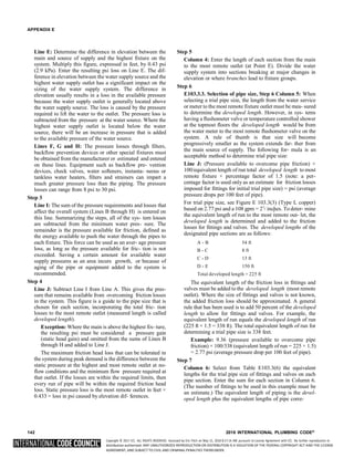
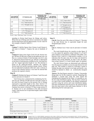

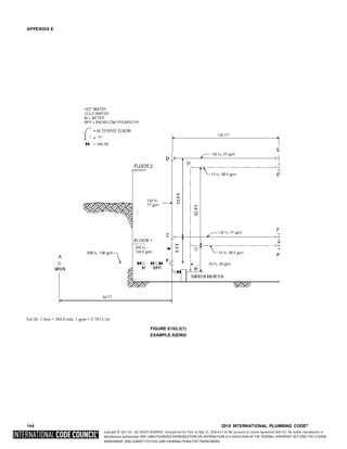
![Copyright © 2017 ICC. ALL RIGHTS RESERVED. Accessed by Eric Fitch on May 15, 2018 8:17:14 AM pursuant to License Agreement with ICC. No further reproduction or
distribution authorized. ANY UNAUTHORIZED REPRODUCTION OR DISTRIBUTION IS A VIOLATION OF THE FEDERAL COPYRIGHT ACT AND THE LICENSE
AGREEMENT, AND SUBJECT TO CIVIL AND CRIMINAL PENALTIES THEREUNDER.
APPENDIX E
TABLE E103.3(1)
RECOMMENDED TABULAR ARRANGEMENT FOR USE IN SOLVING PIPE SIZING PROBLEMS
COLUMN 1 2 3 4 5 6 7 8 9 10
Line Description
Lb per
square
inch
(psi)
Gal. per
min
through
section
Length
of
section
(feet)
Trial
pipe
size
(inches)
Equivalent
length of
fittings
and valves
(feet)
Total
equivalent
length col.
4 and col.
6
(100 feet)
Friction
loss per
100 feet
of trial
size pipe
(psi)
Friction
loss in
equivalent
length col.
8 x col. 7
(psi)
Excess
pressure
over
friction
losses
(psi)
A
B
C
D
E
F
G
H
I
J
Service and
Minimum pressure available at main.............. 55.00
Highest pressure required at a fixture
(Table 604.3).................................................. 15.00
Meter loss 2 meter ......................................... 11.00
Tap in main loss 2 tap
[Table E103.3(4)].......................................... 1.61
Static head loss 21 × 43 psi .............................. 9.03
Special fixture loss backflow
preventer........................................................... 9.00
Special fixture loss—Filter ............................... 0.00
Special fixture loss—Other............................... 0.00
Total overall losses and requirements
(Sum of Lines B through H) ..........................45.64
Pressure available to overcome
pipe friction
(Line A minus Lines B to H) ........................... 9.36
cold water
distribution
pipinga
FU ....................................... 264
DESIGNATION
Pipe section (from diagram)
Cold water
Distribution piping
AB....................................... 288
BC ....................................... 264
CD....................................... 132
CFb .......................................132
108.0
104.5
77.0
77.0
54
8
13
150
21/2
21/2
21/2
21/2
15.00
0.5
7.00
12.00
0.69
0.85
0.20
1.62
3.2
3.1
1.9
1.9
2.21
0.26
0.38
3.08
—
—
—
—
DEb .......................................132 77.0 150 21/
2 12.00 1.62 1.9 3.08 —
K Total pipe friction losses (cold) — — — — — — 5.93 —
L Difference (Line J minus Line K) — — — — — — — 3.43
Pipe section (from diagram) AB..................................... 288 108.0 54 21/2
2
11/2
11/2
11/
2
12.00 0.69 3.3 2.21 —
Diagram BC ....................................... 24 38.0 8 7.5 0.16 1.4 0.22 —
Hot water CD....................................... 12 28.6 13 4.0 0.17 3.2 0.54 —
Distribution CFb........................................12 28.6 150 7.00 1.57 3.2 5.02 —
Piping DEb .......................................12 28.6 150 7.00 1.57 3.2 5.02 —
K Total pipe friction losses (hot) — — — — — — 7.99 —
L Difference (Line J minus Line K) — — — — — — — 1.37
For SI: 1 inch = 25.4 mm, 1 foot = 304.8 mm, 1 psi = 6.895 kPa, 1 gpm = 3.785 L/m.
a. To be considered as pressure gain for fixtures below main (to consider separately, omit from “I” and add to “J”).
b. To consider separately, in K use C-F only if greater loss than above.
2018 INTERNATIONAL PLUMBING CODE® 145](https://image.slidesharecdn.com/2018-ipc-international-plumbing-code-241129135518-3483e2e4/85/2018-IPC-International-Plumbing-Code-pdf-214-320.jpg)
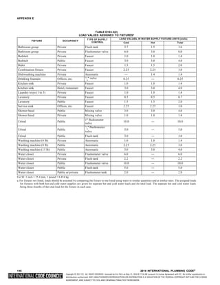
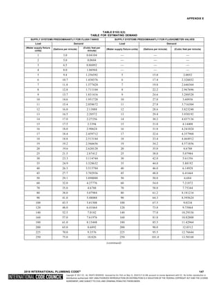
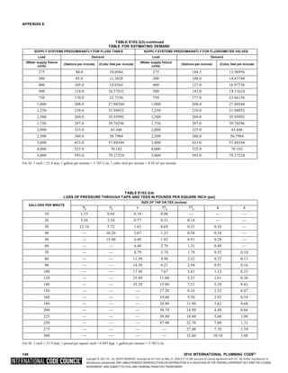
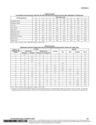
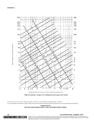
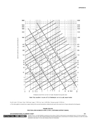
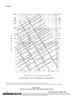
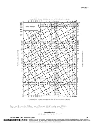
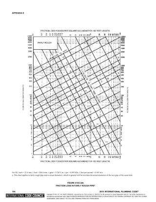
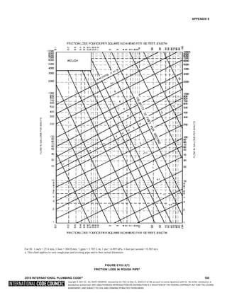
![Copyright © 2017 ICC. ALL RIGHTS RESERVED. Accessed by Eric Fitch on May 15, 2018 8:17:14 AM pursuant to License Agreement with ICC. No further reproduction or
distribution authorized. ANY UNAUTHORIZED REPRODUCTION OR DISTRIBUTION IS A VIOLATION OF THE FEDERAL COPYRIGHT ACT AND THE LICENSE
AGREEMENT, AND SUBJECT TO CIVIL AND CRIMINAL PENALTIES THEREUNDER.
APPENDIX E
SECTION E201
SELECTION OF PIPE SIZE
E201.1 Size of water service mains, branch mains and ris-
equal to or greater than the calculated maximum devel-
oped length.
4. To determine the size of water service pipe, meter and
ers. The minimum size water service pipe shall be 3
/ inch main distribution pipe to the building using the appro-
(19.1 mm). The size of water service mains, branch mainsand
risers shall be determined according to water supply demand
[gpm (L/m)], available water pressure [psi (kPa)] and friction
loss due to the water meter and developed length of pipe [feet
(m)], including equivalent length of fittings. The size of each
water distribution system shall be determined according to the
procedure outlined in this section or by other design methods
conforming to acceptable engineering prac- tice and approved
by the code official:
1. Supply load in the building water distribution system
shall be determined by total load on the pipe being sized,
in terms of water-supply fixture units (w.s.f.u.), as
shown in Table E103.3(2). For fixtures not listed, choose
a w.s.f.u. value of a fixture with similar flow
characteristics.
2. Obtain the minimum daily static service pressure [psi
(kPa)] available (as determined by the local water
authority) at the water meter or other source of supply
at the installation location. Adjust this minimum daily
static pressure [psi (kPa)] for the following conditions:
2.1. Determine the difference in elevation between the
source of supply and the highest water sup- ply
outlet. Where the highest water supply out- let is
located above the source of supply, deduct
0.5 psi (3.4 kPa) for each foot (0.3 m) of differ-
ence in elevation. Where the highest water sup-
ply outlet is located below the source of supply,
add 0.5 psi (3.4 kPa) for each foot (0.3 m) of
difference in elevation.
2.2. Where a water pressure-reducing valve is
installed in the water distribution system, the
minimum daily static water pressure available is
80 percent of the minimum daily static water
pressure at the source of supply or the set pres-
sure downstream of the pressure-reducing valve,
whichever is smaller.
2.3. Deduct all pressure losses due to special equip-
ment such as a backflow preventer, water filter
and water softener. Pressure loss data for each
piece of equipment shall be obtained throughthe
manufacturer of such devices.
2.4. Deduct the pressure in excess of 8 psi (55 kPa)
due to installation of the special plumbing fix-
ture, such as temperature controlled shower and
flushometer tank water closet. Using the result-
ing minimum available pressure, find the corre-
sponding pressure range in Table E201.1.
3. The maximum developed length for water piping is the
actual length of pipe between the source of supplyand the
most remote fixture, including either hot (through the
water heater) or cold water branches multiplied by a
factor of 1.2 to compensate for pressure loss through
fittings. Select the appropriate column in Table E201.1
priate table, follow down the selected “maximum
developed length” column to a fixture unit equal to, or
greater than the total installation demand calculated by
using the “combined” water supply fixture unit column
of Table E103.3(2). Read the water service pipe and
meter sizes in the first left-hand column and the main
distribution pipe to the building in the second left-hand
column on the same row.
5. To determine the size of each water distribution pipe,
start at the most remote outlet on each branch (either hot
or cold branch) and, working back toward the main
distribution pipe to the building, add up the water sup- ply
fixture unit demand passing through each segmentof the
distribution system using the related hot or cold column
of Table E103.3(2). Knowing demand, the size of each
segment shall be read from the second left-hand column
of the same table and maximum developed length column
selected in Steps 1 and 2, under the same or next smaller
size meter row. The size of any branchor main does not
need to be larger than the size of the main distribution
pipe to the building established in Step 4.
SECTION E202
DETERMINATION OF PIPE VOLUMES
E202.1 Determining volume of piping systems. Where
required for engineering design purposes, Table E202.1 shall be
used to determine the approximate internal volume of water
distribution piping.
4](https://image.slidesharecdn.com/2018-ipc-international-plumbing-code-241129135518-3483e2e4/85/2018-IPC-International-Plumbing-Code-pdf-225-320.jpg)