This document discusses radiation protection and safety criteria related to ionizing radiation. It begins by defining radiation hazards and outlining the biological effects of radiation exposure, which can be either deterministic or probabilistic. Key aspects of radiation protection covered include determining radiation hazards, evaluating radiation doses, and the principles and recommendations established by the International Commission on Radiological Protection. The document then provides examples of calculating radiation intensity and shielding requirements for various radiation sources and energies. It emphasizes protecting workers and the public through principles of time, distance and shielding, and highlights planning considerations for medical x-ray facilities to ensure safe and compliant operation.


![(RF) = W U T / P d2
= (400 X1 X1)/(2 X 22
[distance from X-ray source])
= 50
= 2n
or 10n
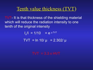
= 5.64 HVT or 1.69 TVT
Shielding thickness for concrete
= 1.69 X 5.5 = 9.29 cm of concrete
OR = 9.29 X 2.35/1.5 = 14.55 cm of brick](https://image.slidesharecdn.com/2016-hm-iii-rad-180217050125/85/2018-hm-RADATION-PROTECTION-78-320.jpg)


