This lecture discusses several topics in nanotechnology including fuel cells, nano-composite materials, nanoelectronics, photonic devices, chemical and biological detectors, and applications in nanomedicine. Specifically, the lecture covers:
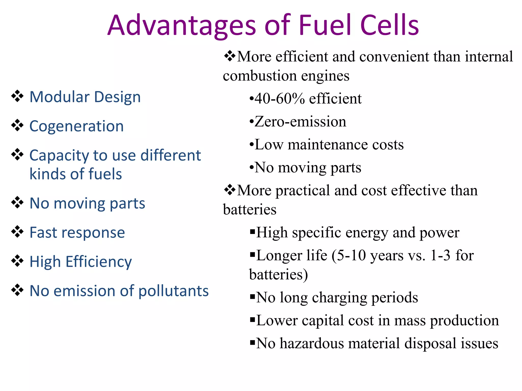
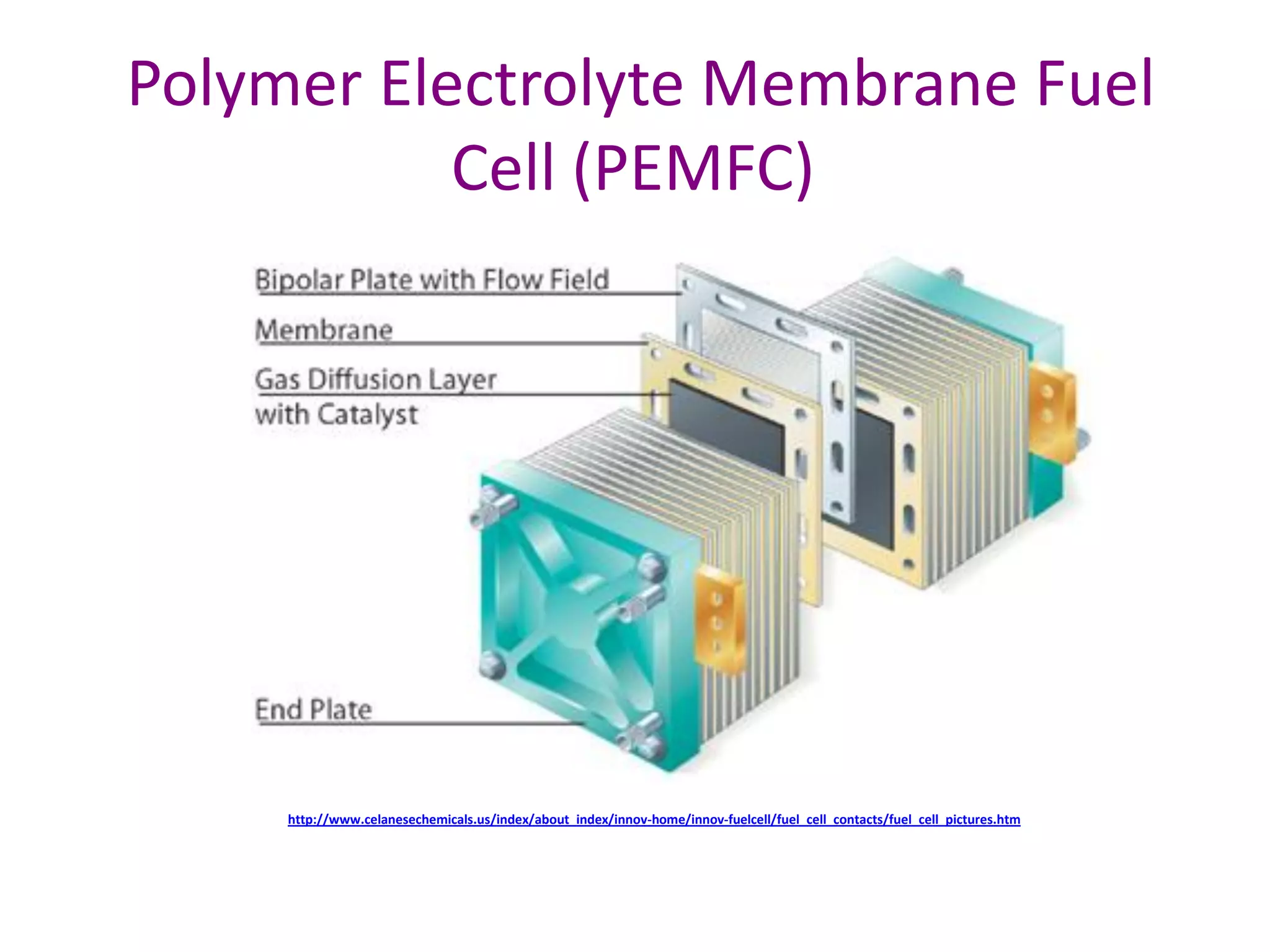
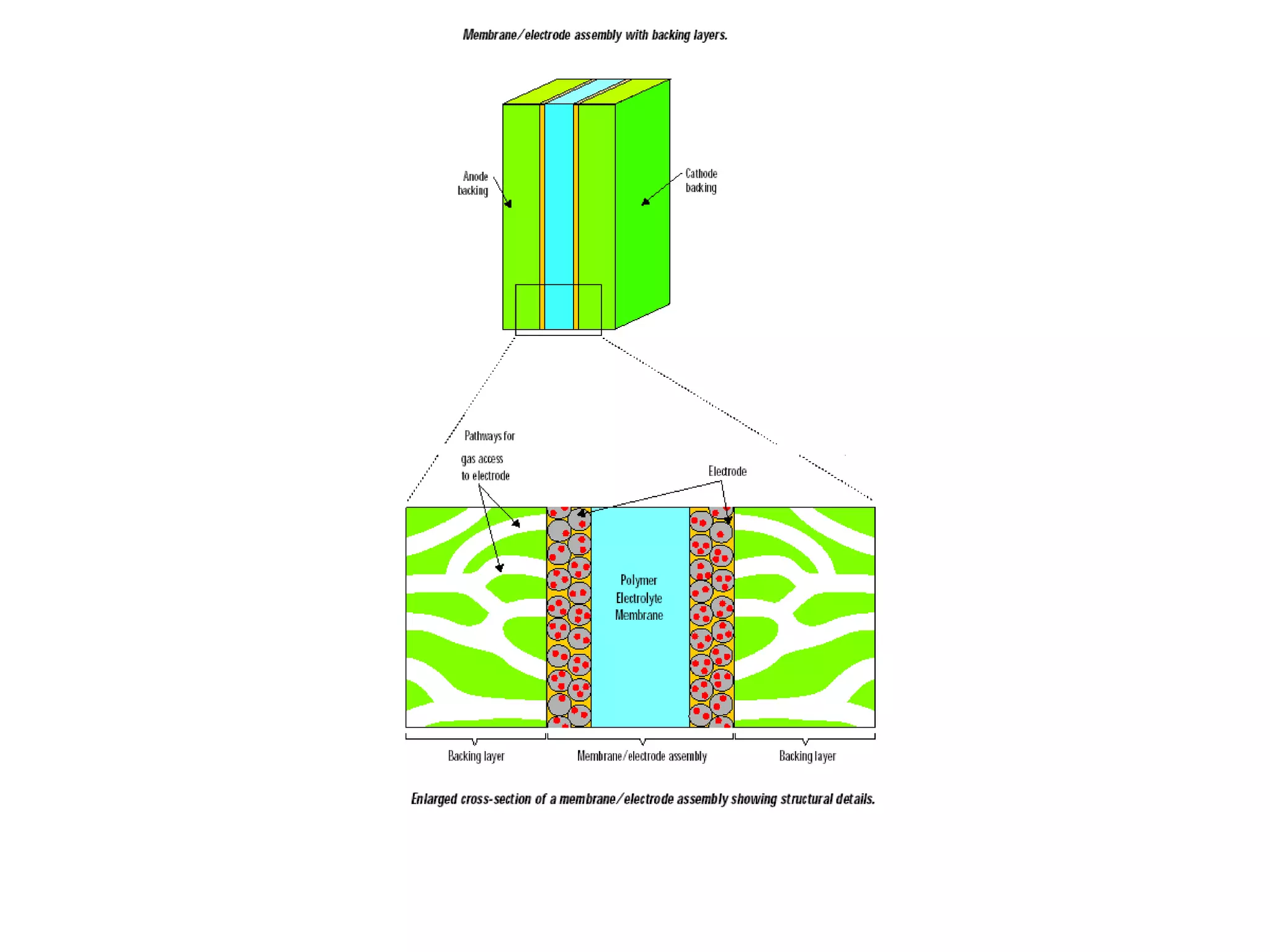
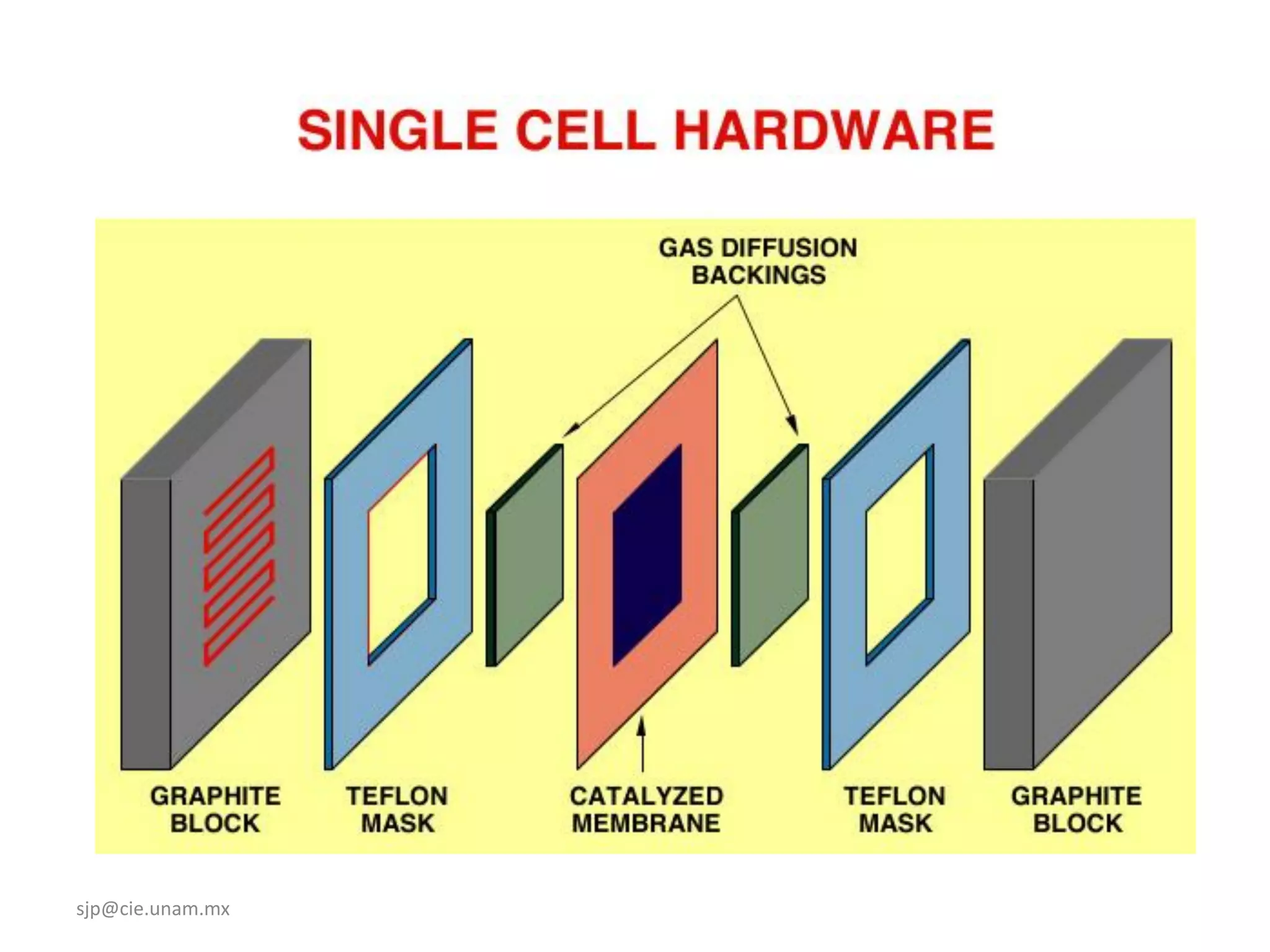
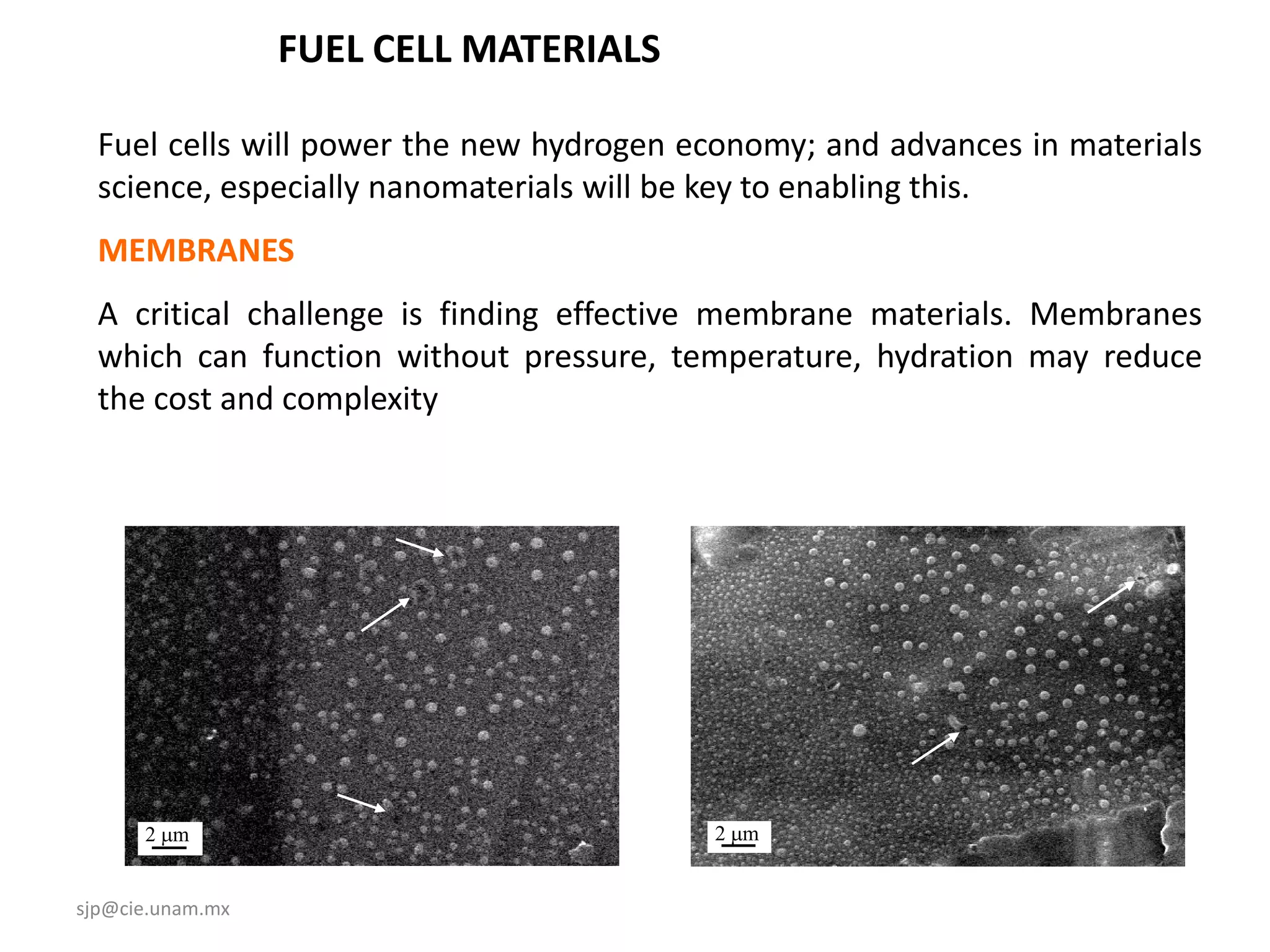
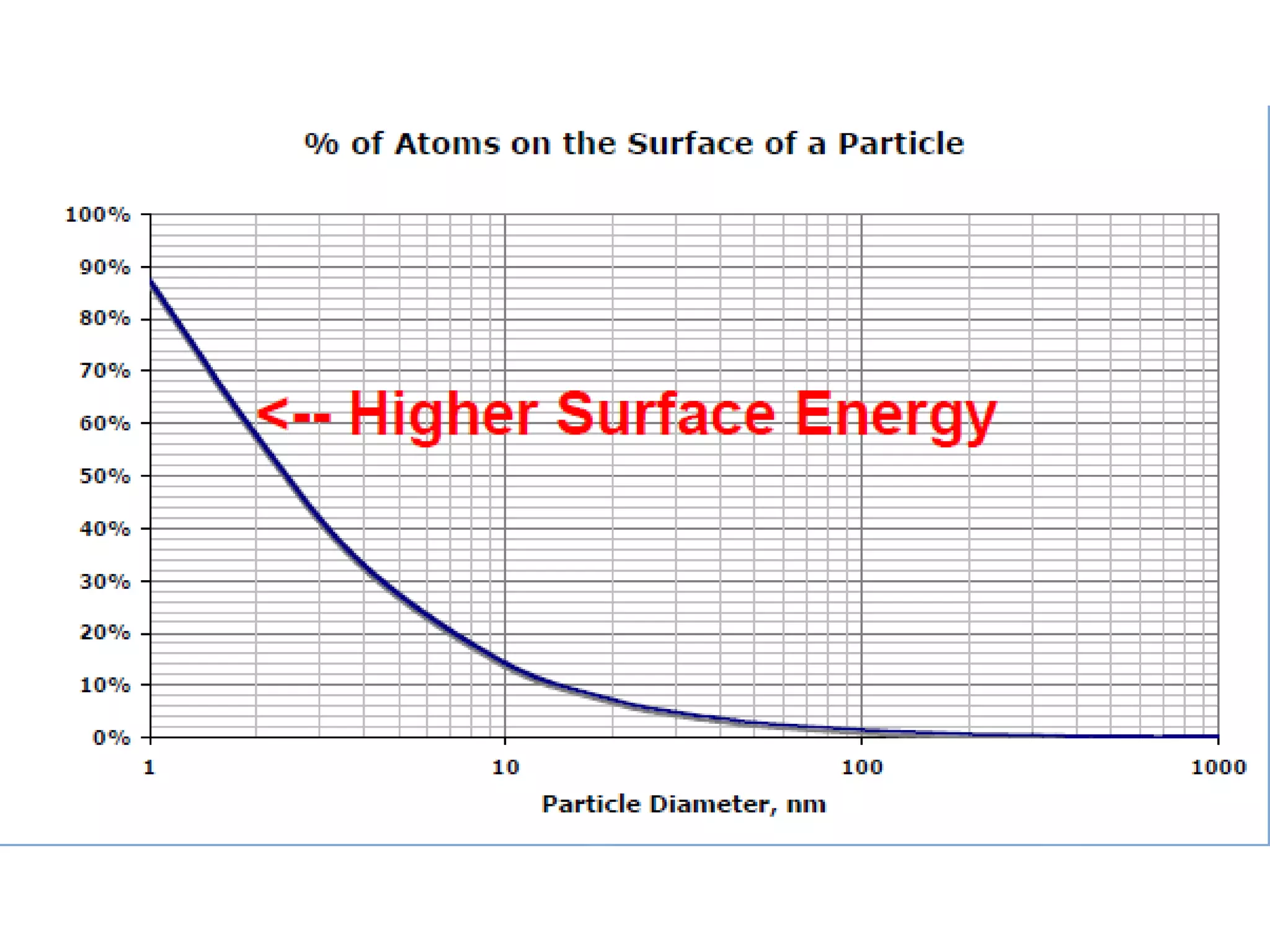
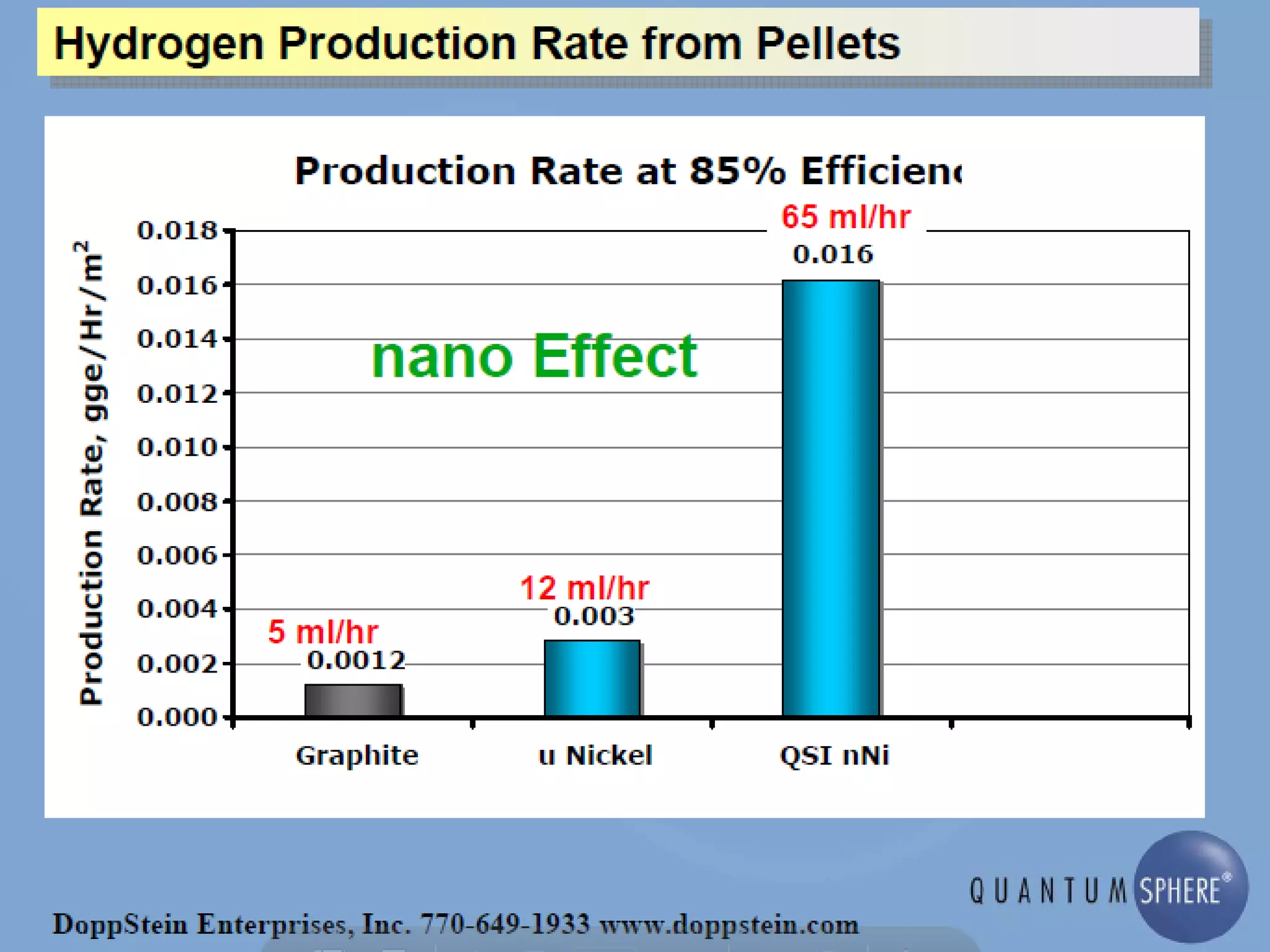
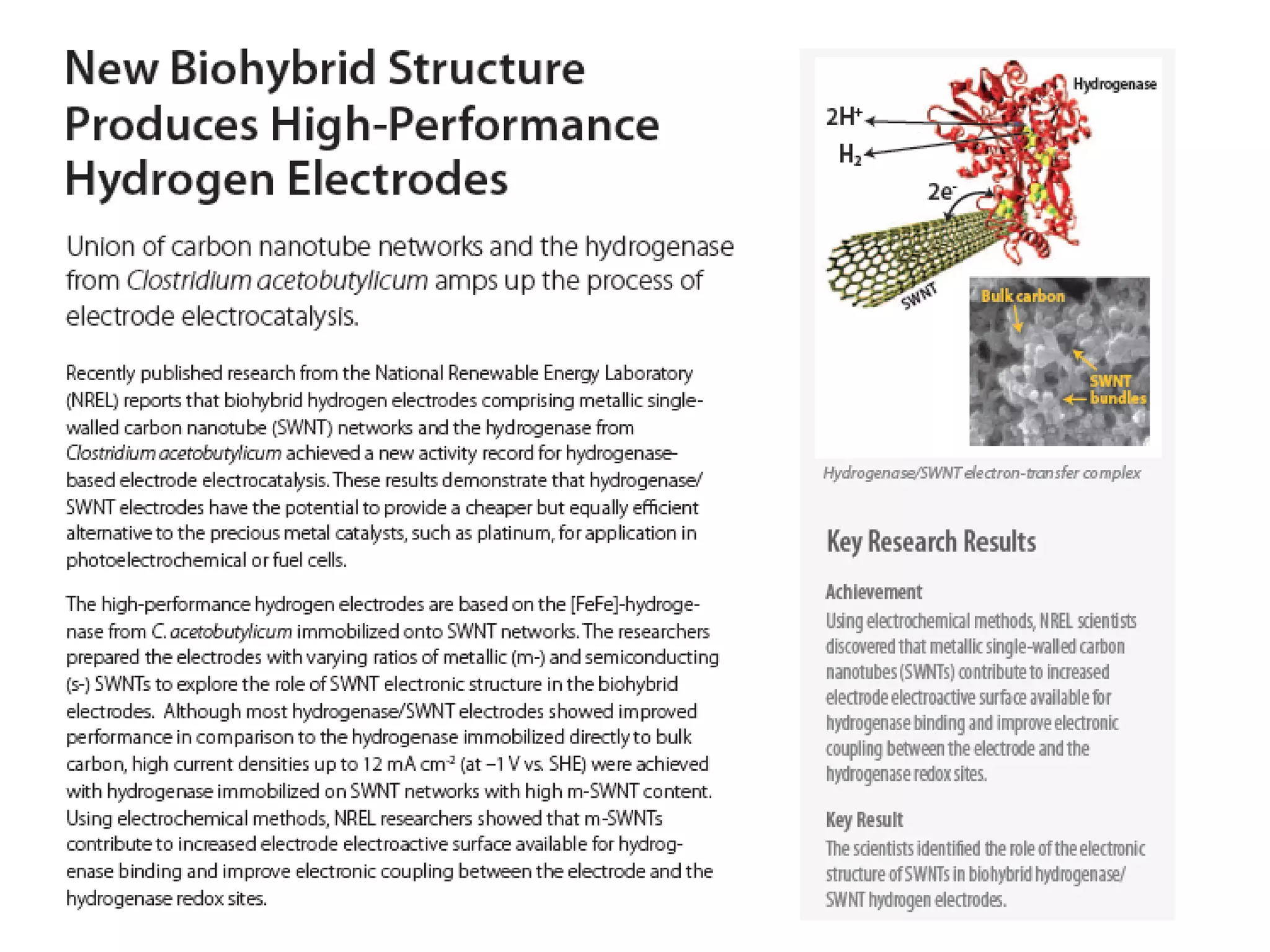
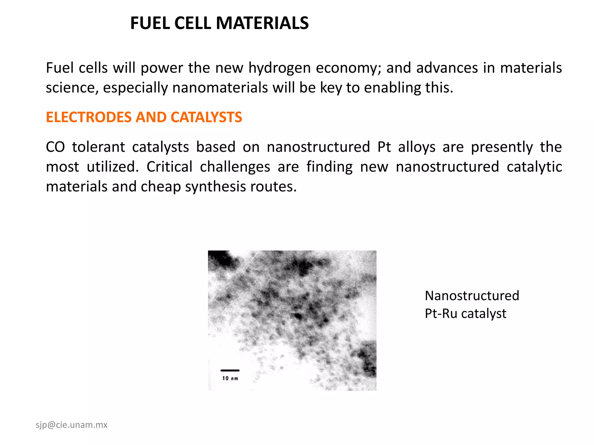
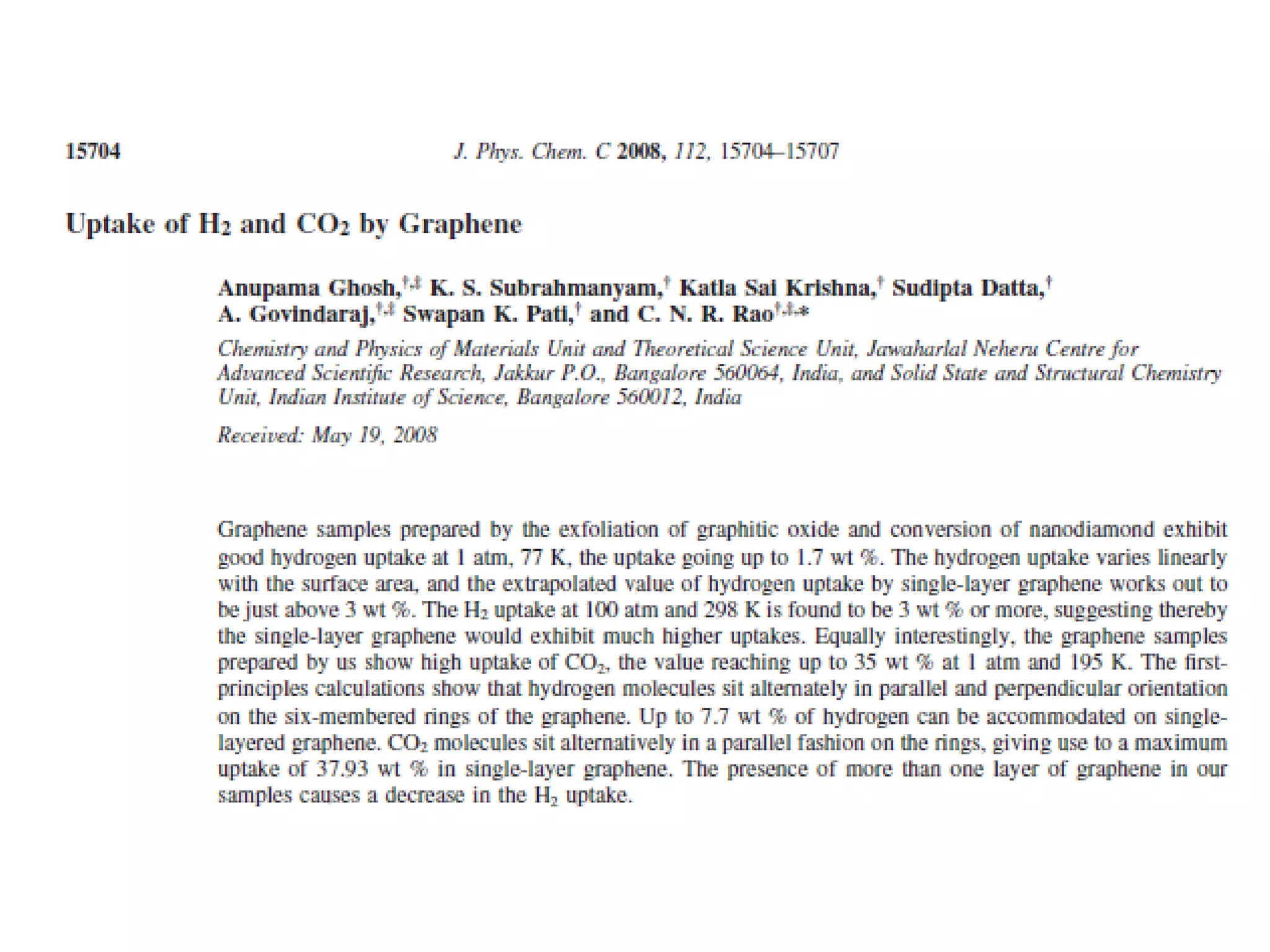
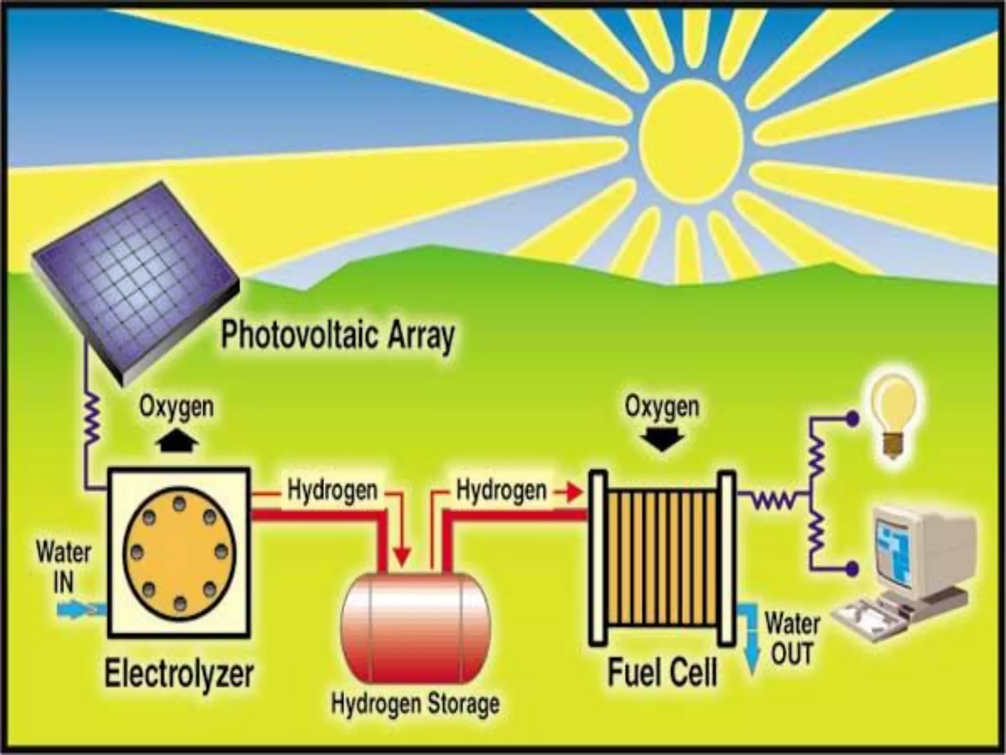
1) Fuel cells and the advantages of using nanomaterials like membranes and catalysts to improve efficiency.
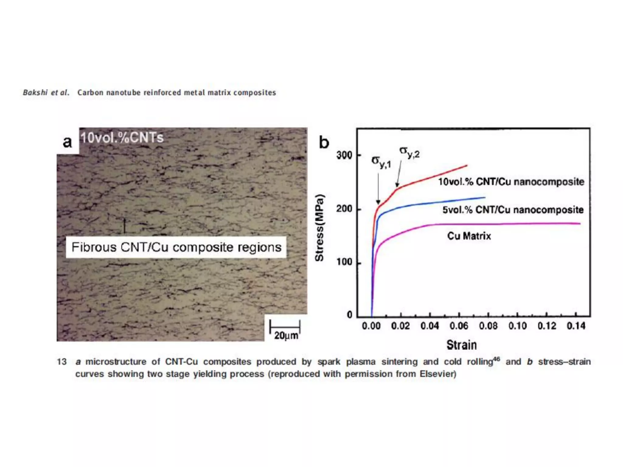
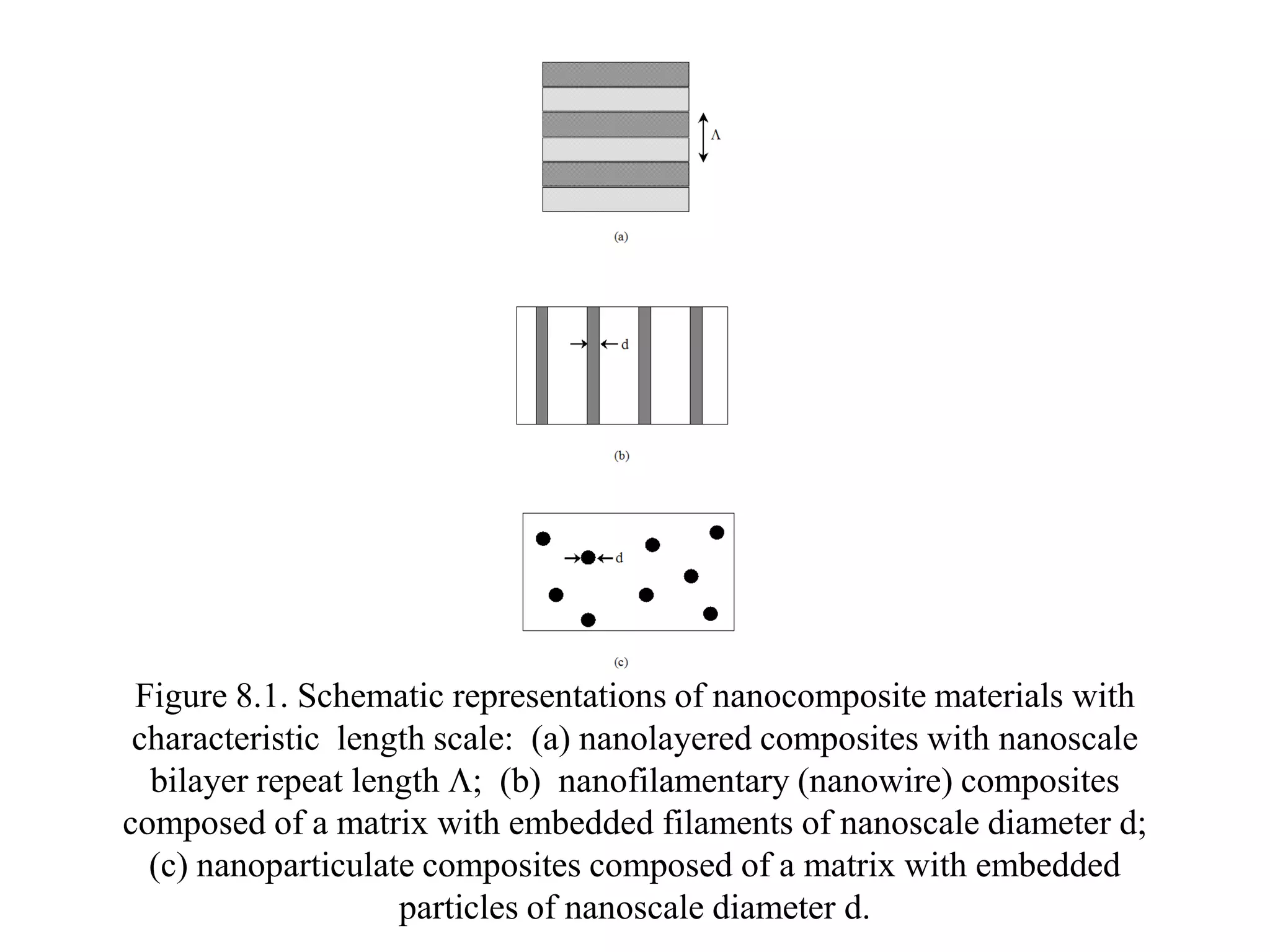
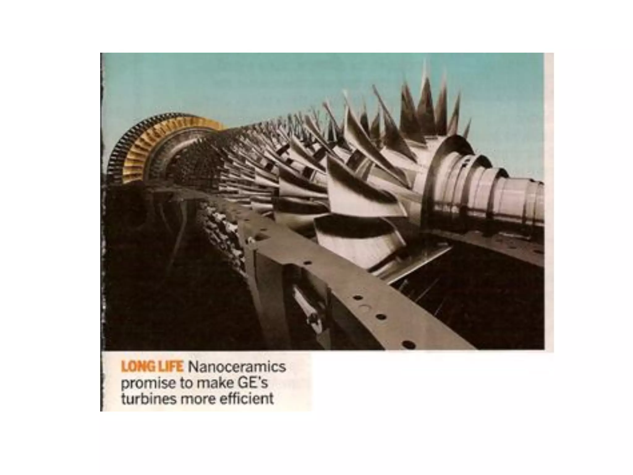
2) Nano-composite materials and their use in applications like reinforced composites with nanotubes or nanoparticles.
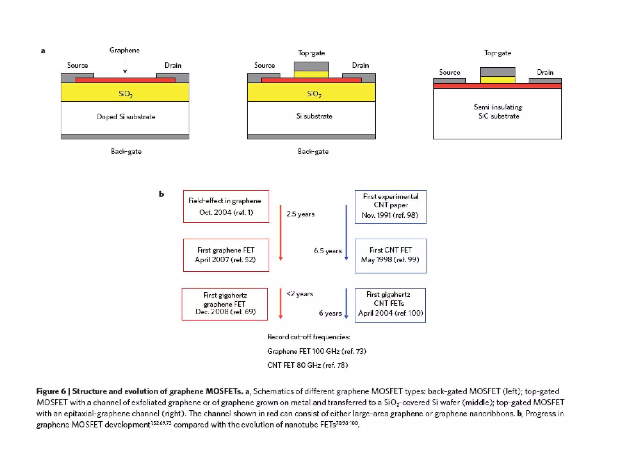
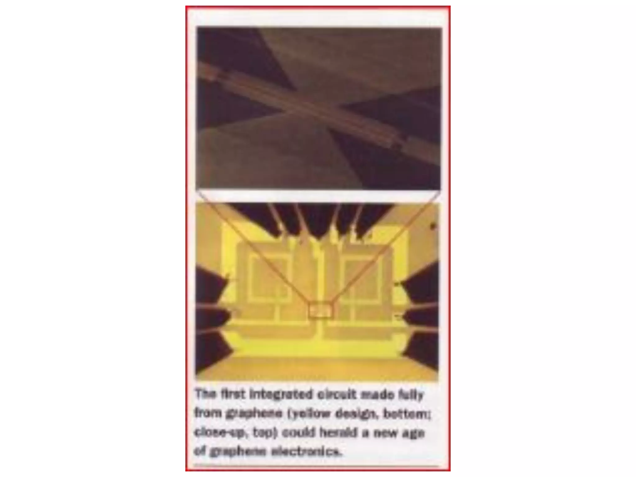
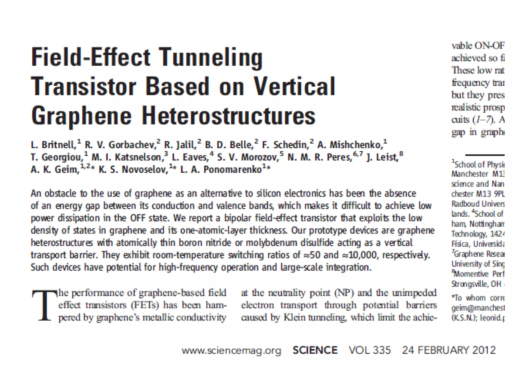
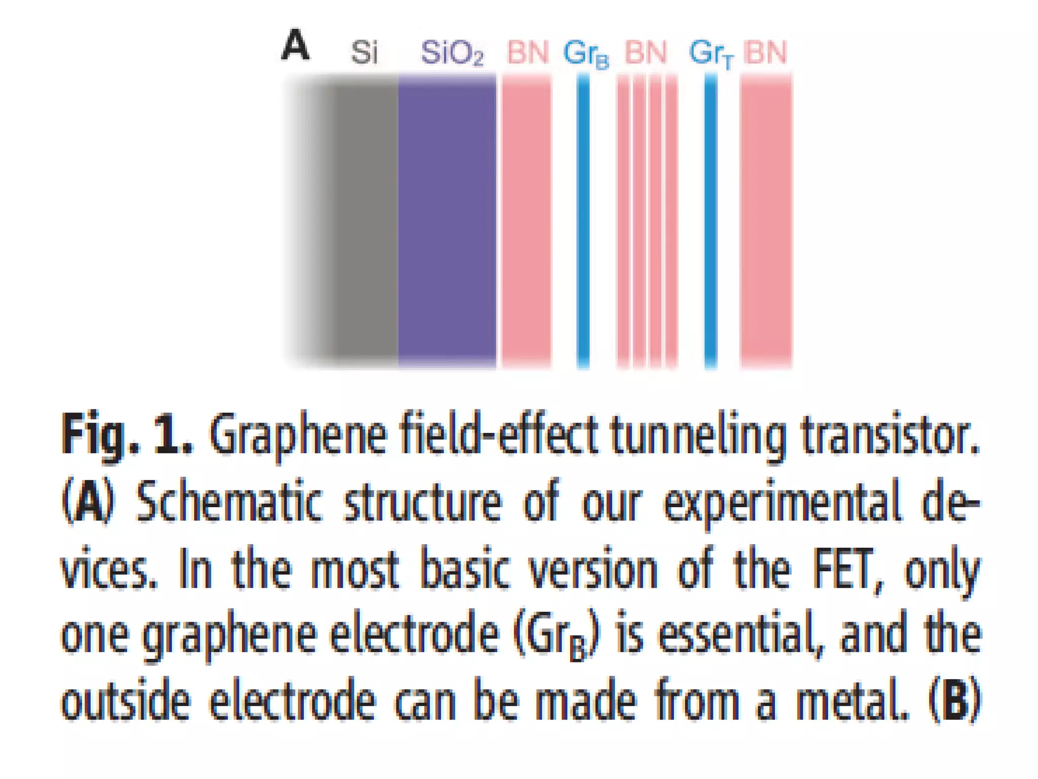
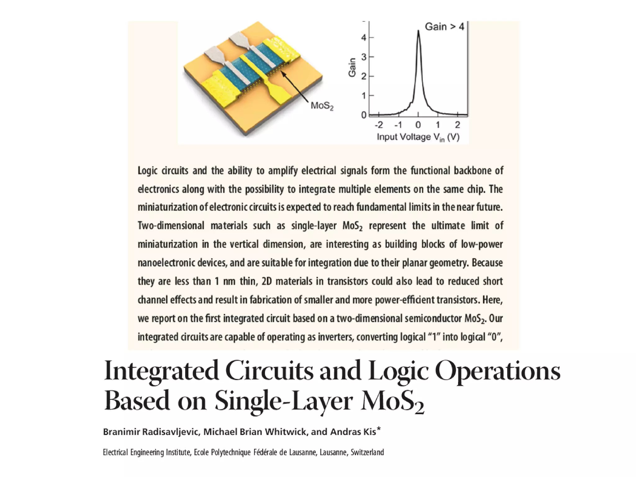
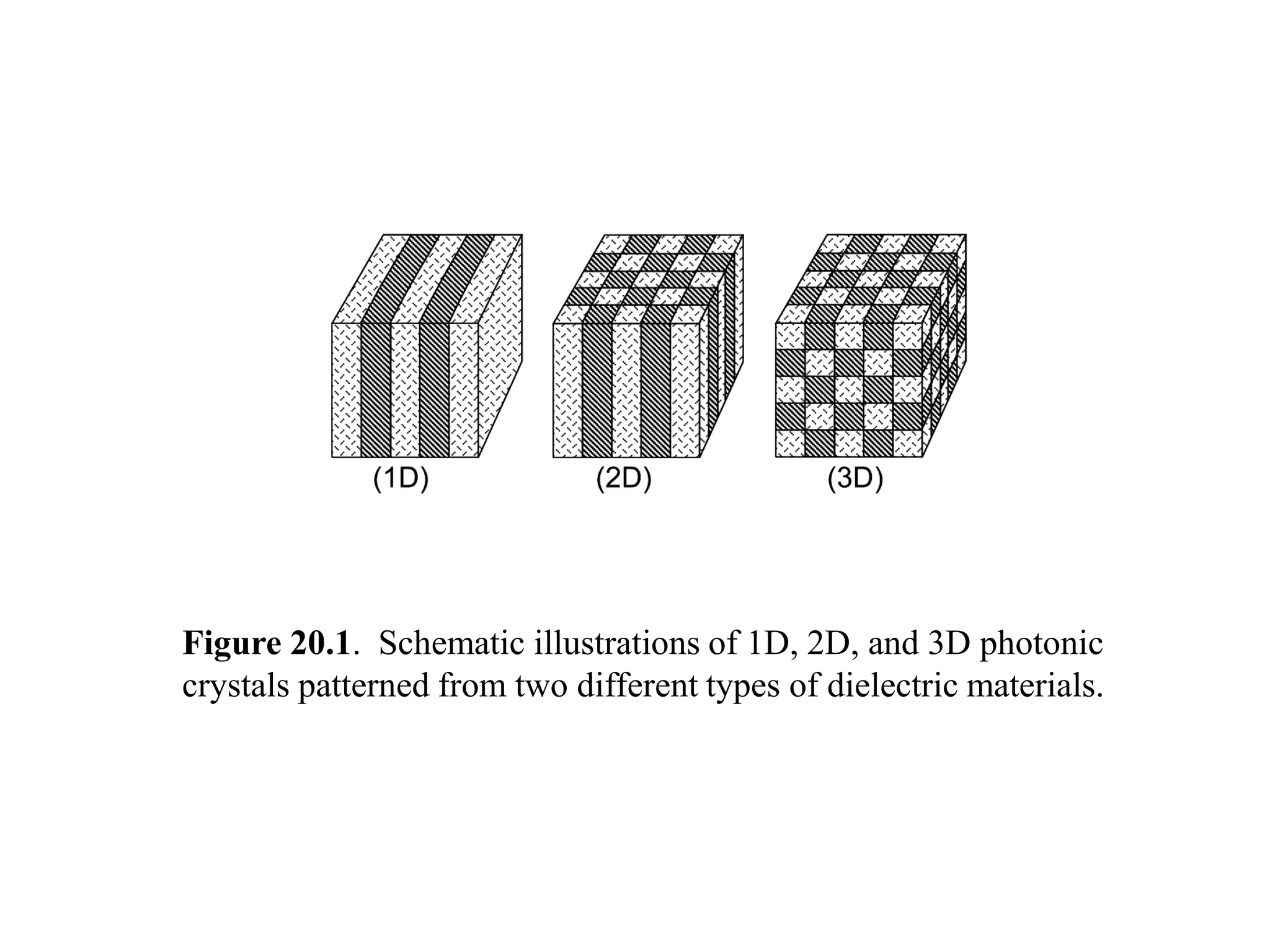
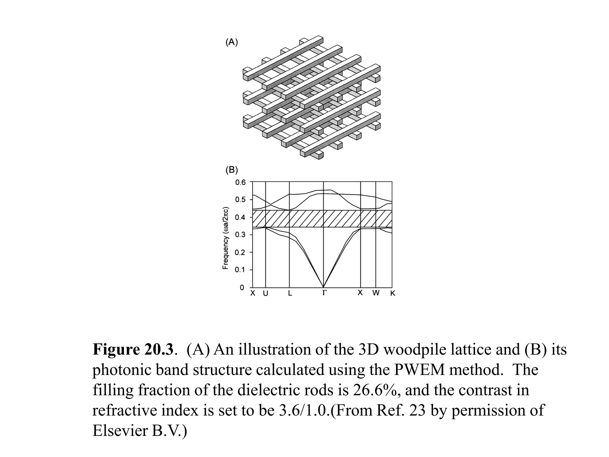
3) Nanoelectronic and photonic devices like transistors, photonic crystals, and integrated photonics.
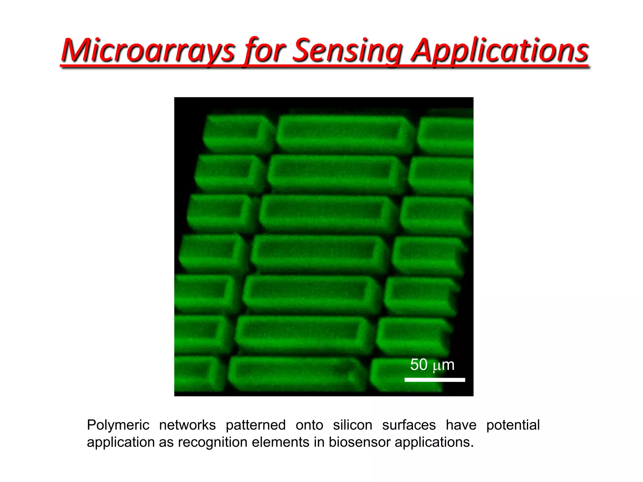
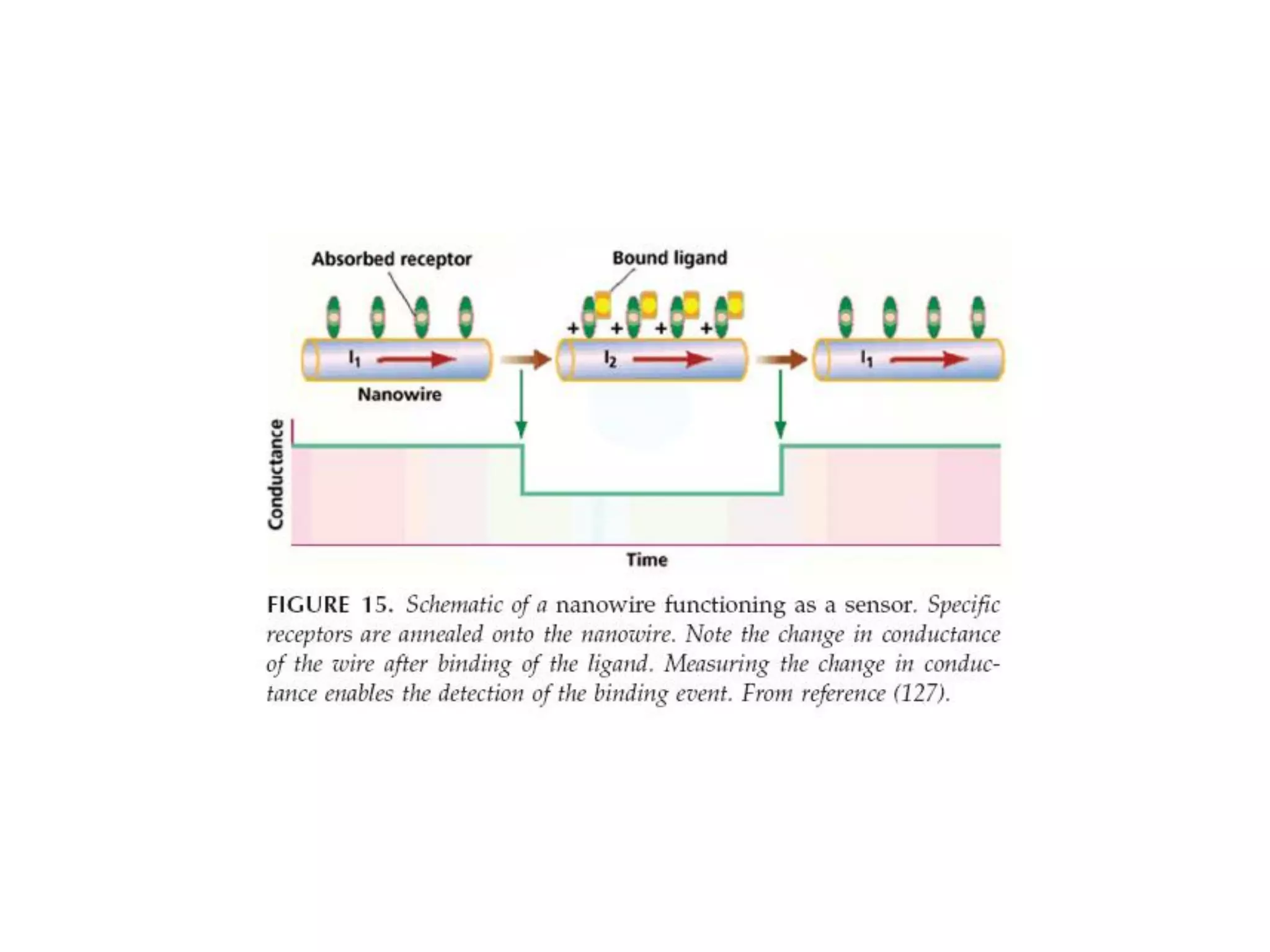
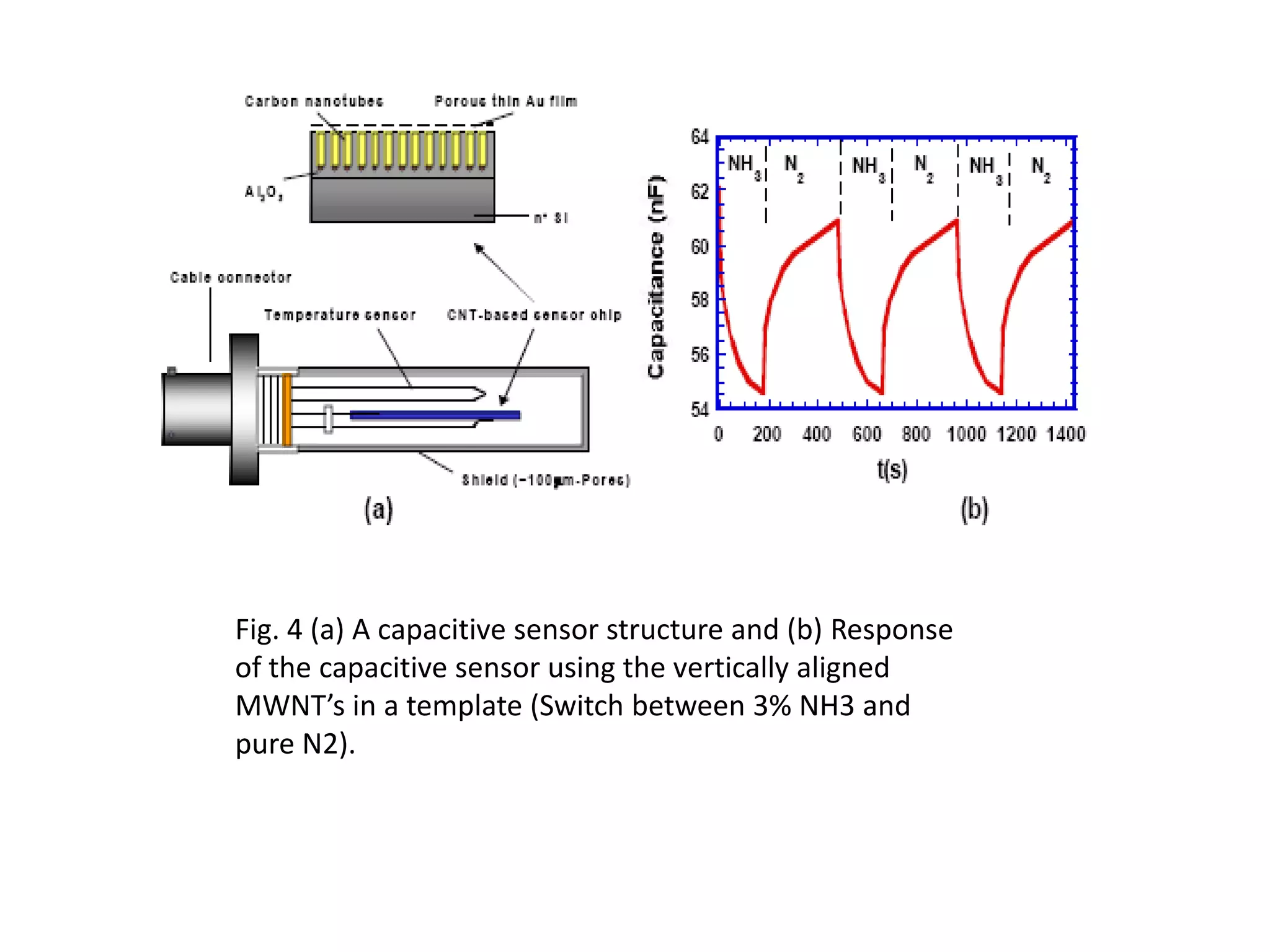
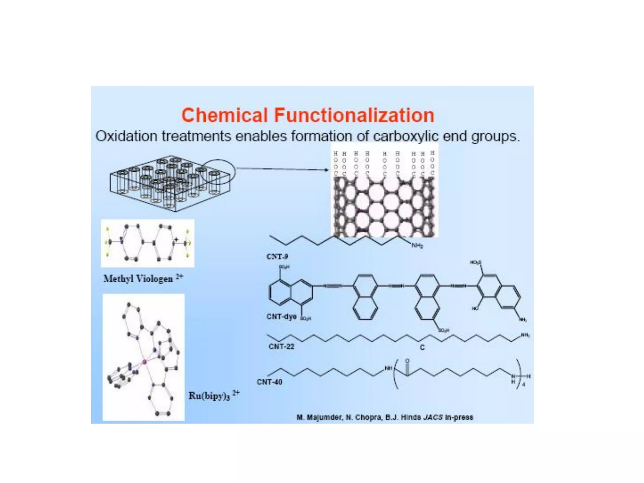
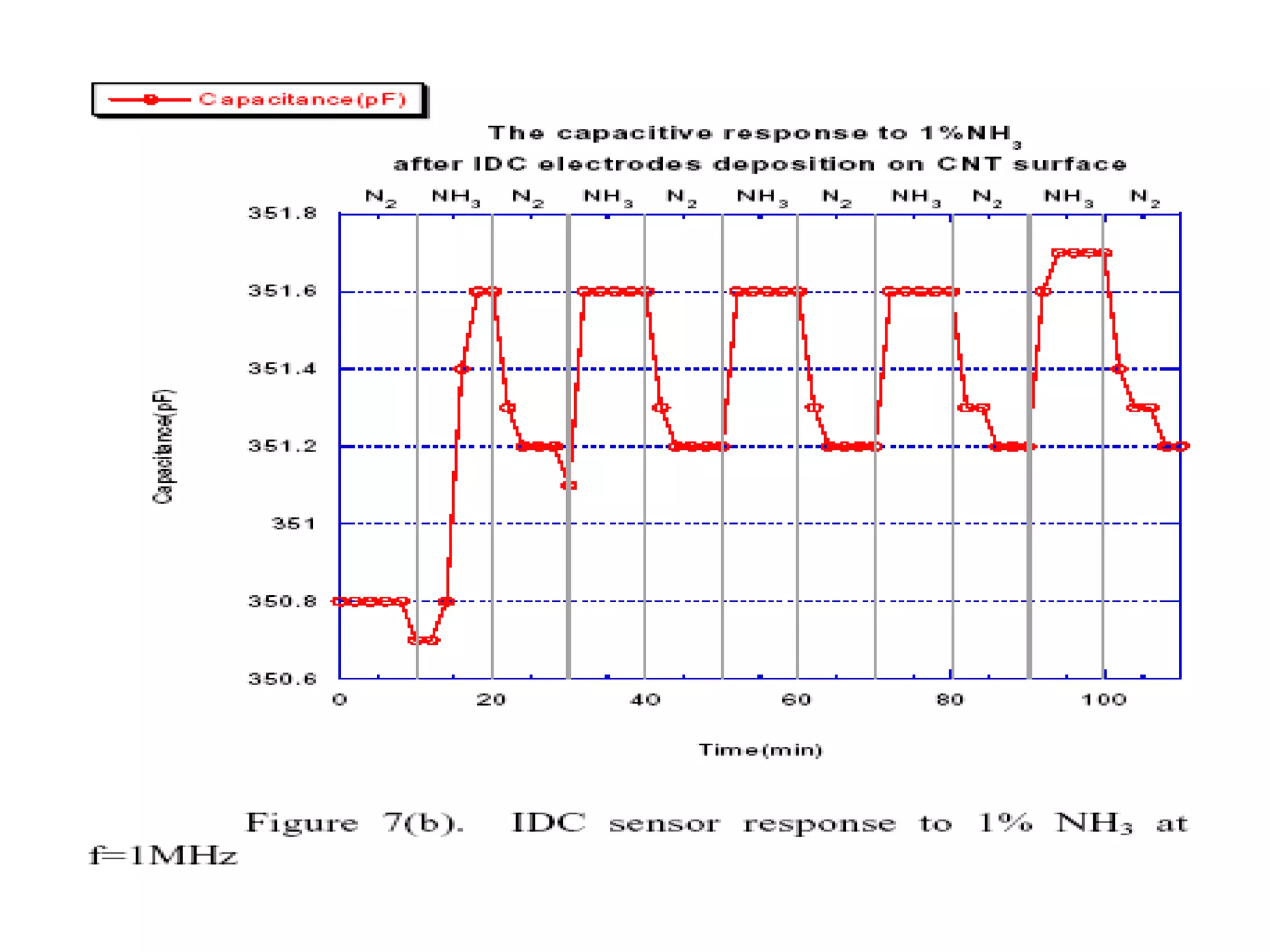
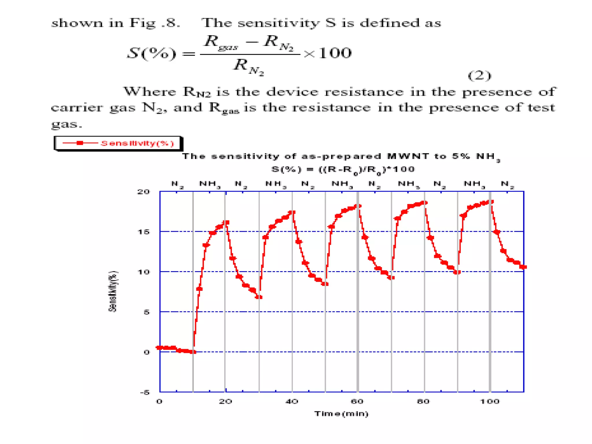
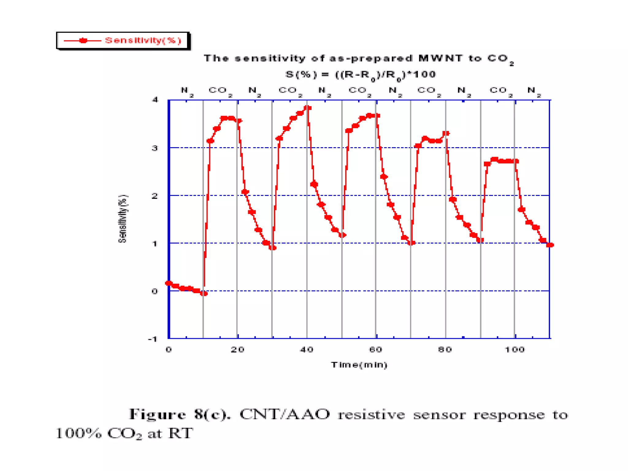
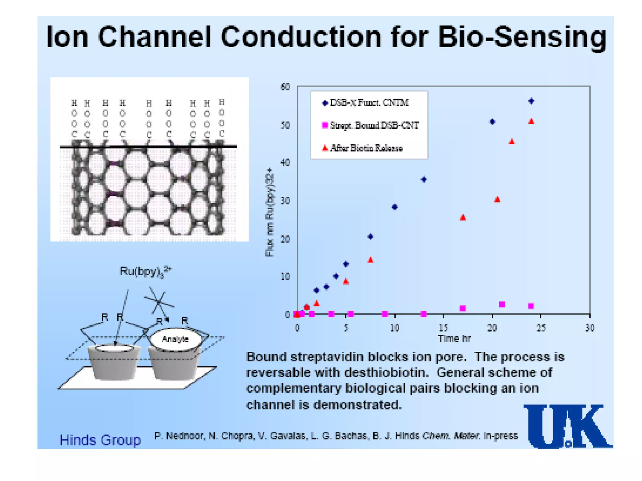
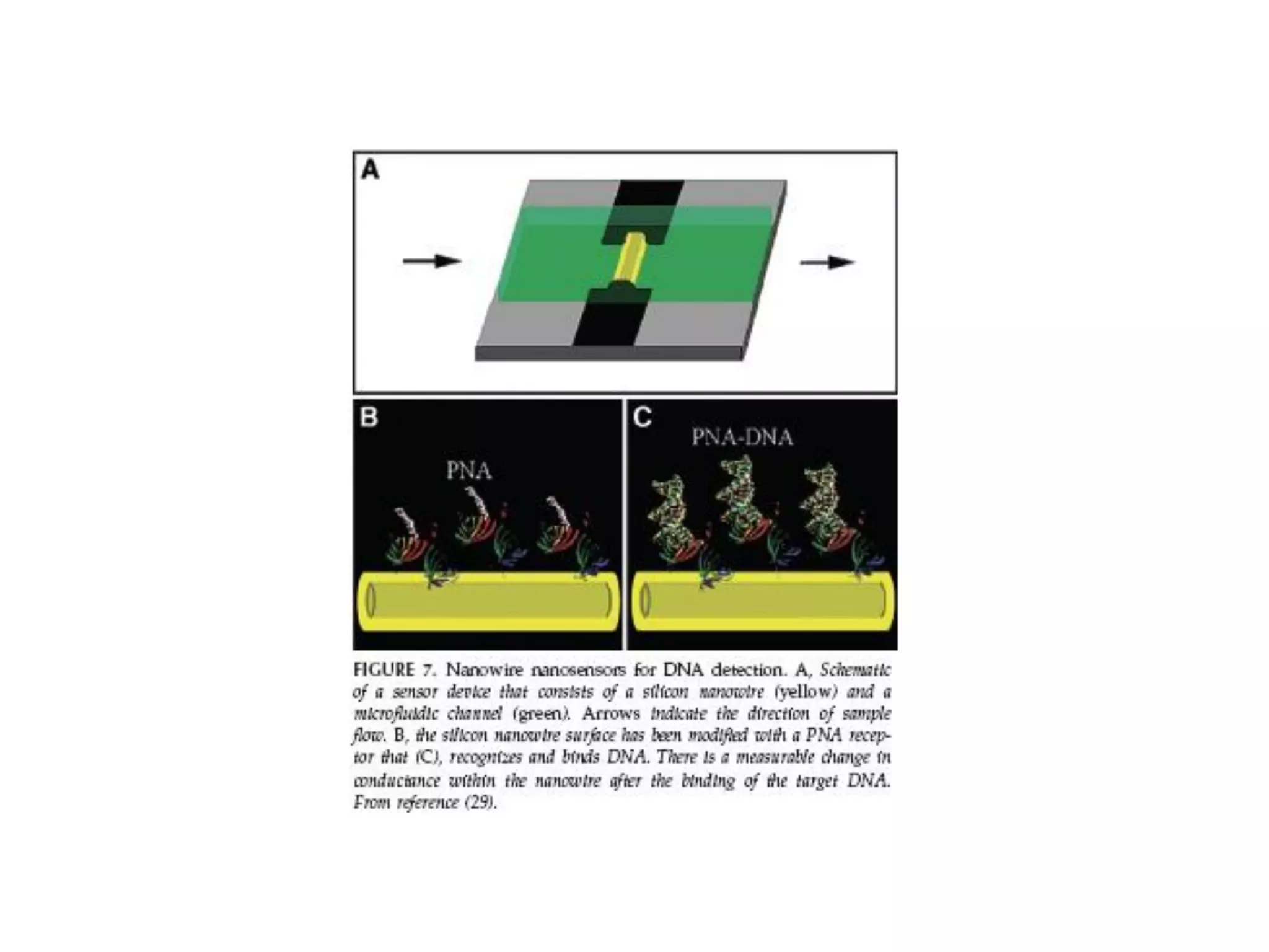
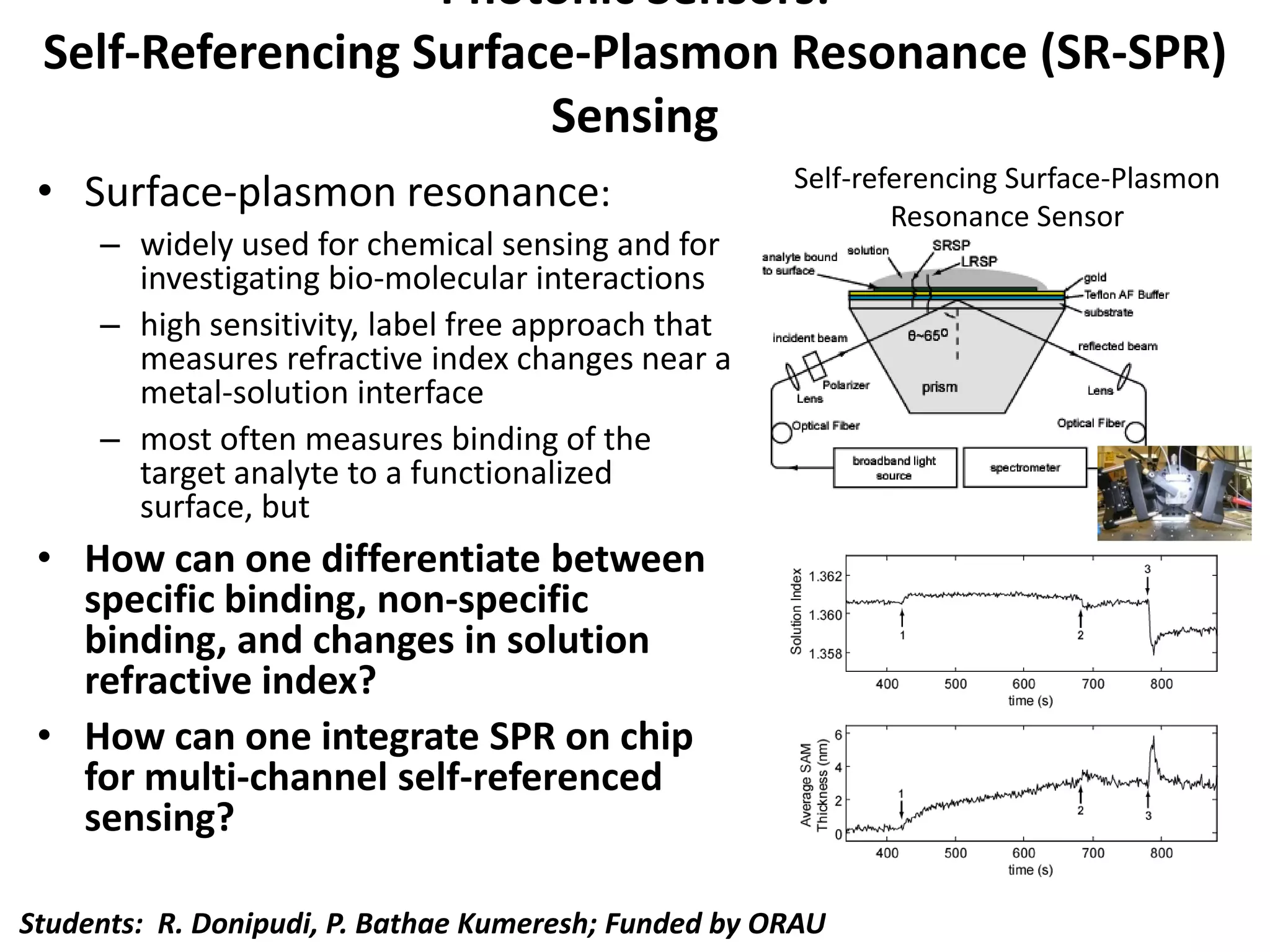
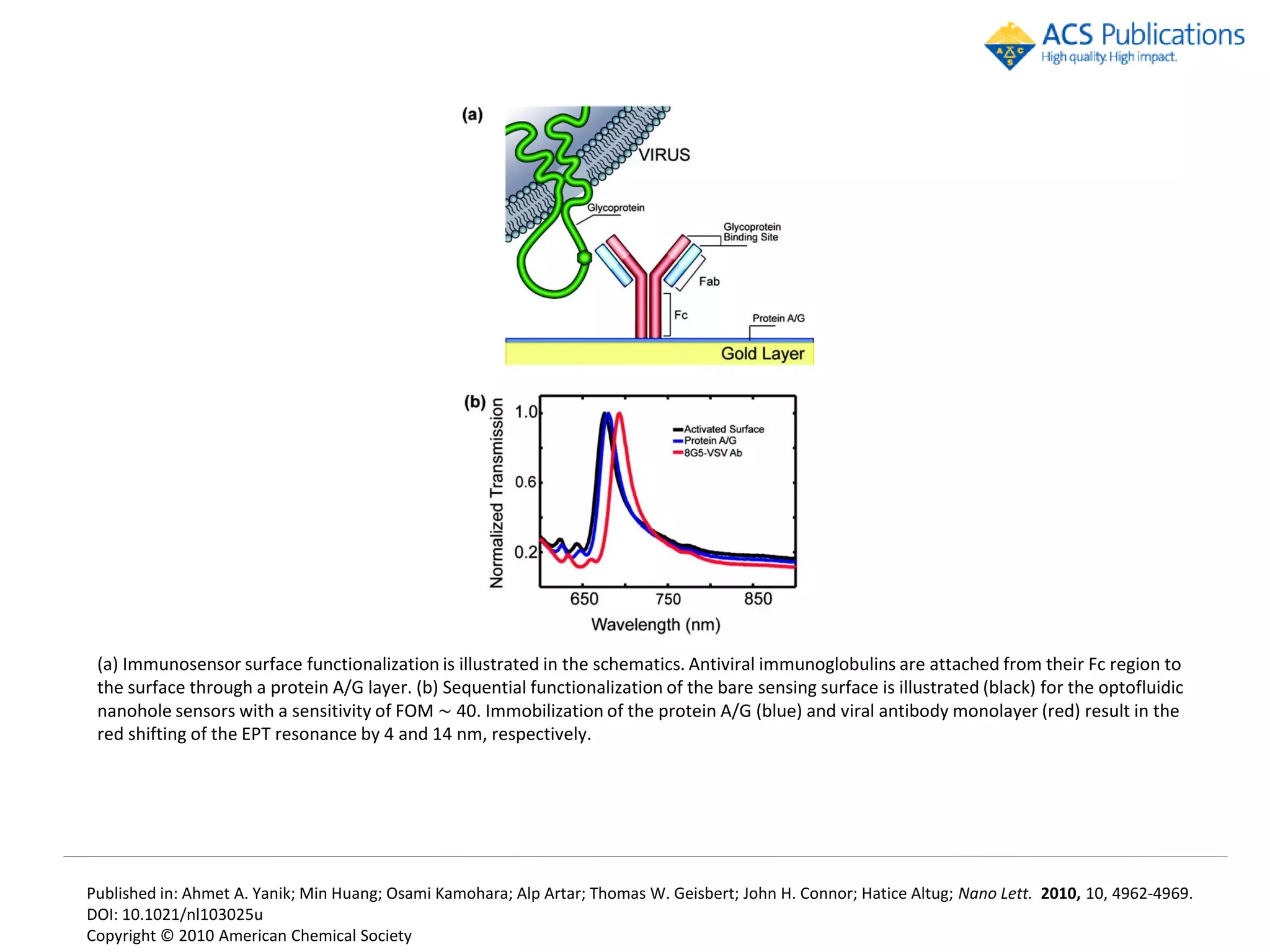
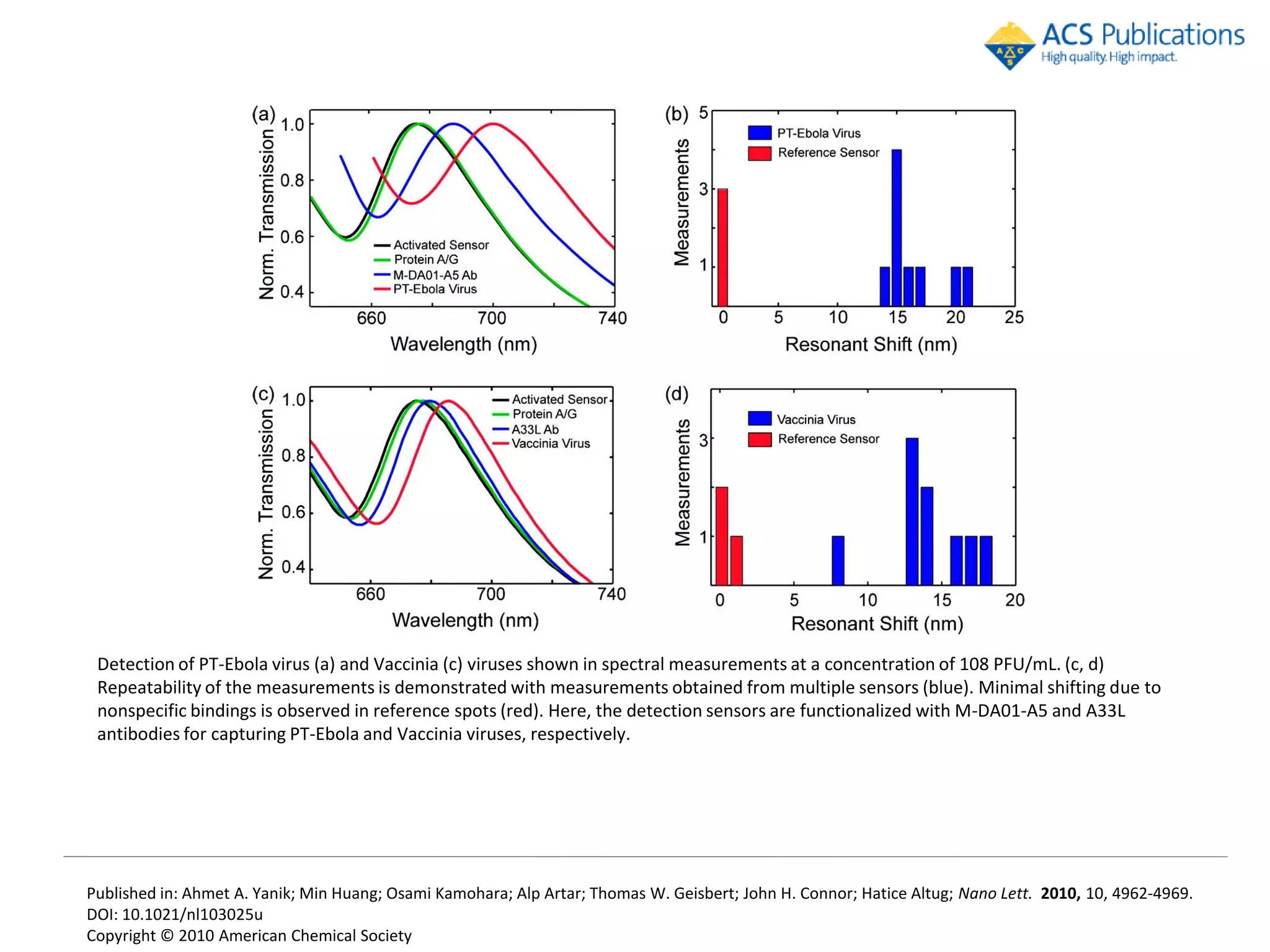
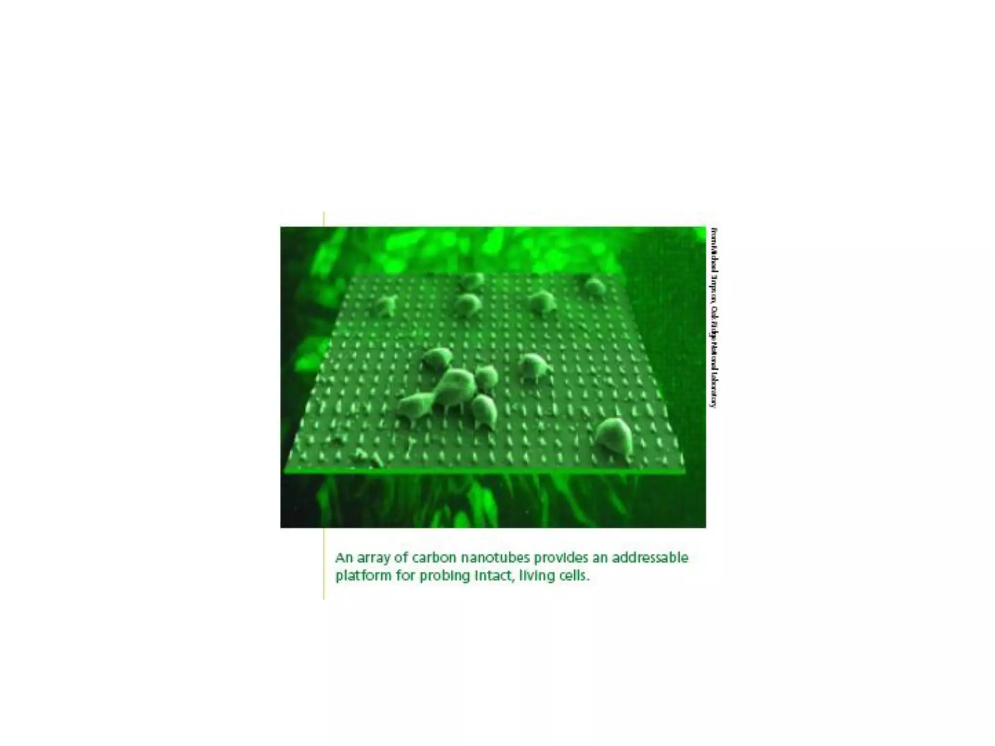
4) Chemical and biological detectors using techniques like microarrays, carbon nanotubes, and surface plasmon resonance.
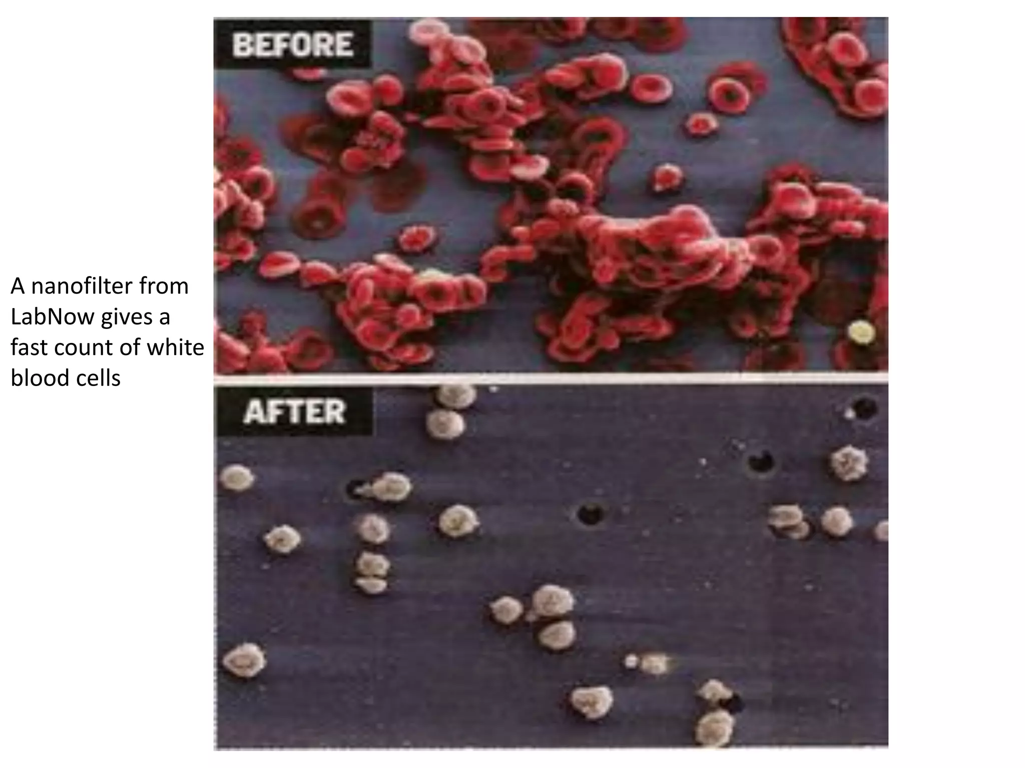
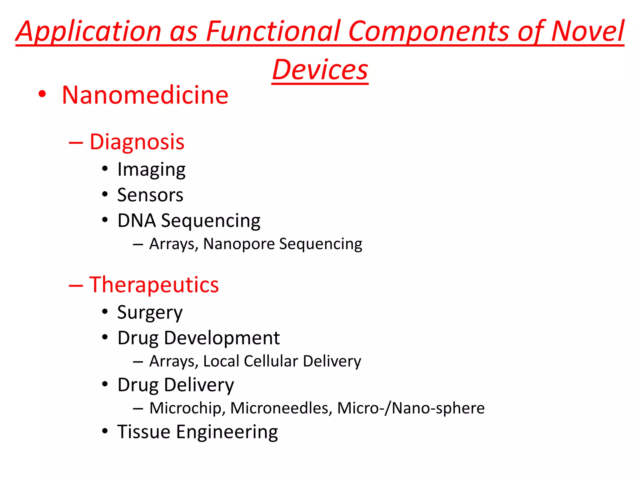
5) Applications in nan
![Fig. 1 Scanning-electron micrograph
of a Silicon-on-insulator integrated-
phontonic Device. [2,3]](https://image.slidesharecdn.com/2012tuslecture6-120501150325-phpapp01/75/2012-tus-lecture-6-20-2048.jpg)