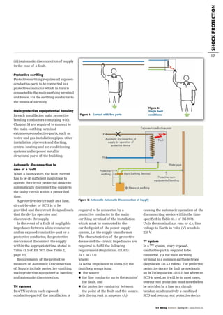
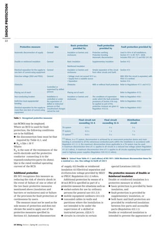
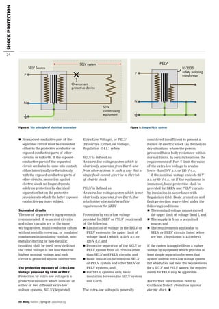
This document discusses various protective measures against electric shock as defined in BS 7671. It describes the key principles of basic protection, which protects against direct contact with live parts under normal conditions, and fault protection, which protects against indirect contact with normally non-live parts that have become live due to a fault. The main protective measures discussed are automatic disconnection of supply, double/reinforced insulation, electrical separation, and extra-low voltage provided by SELV or PELV. Requirements for each measure are outlined, including how basic and fault protection are provided. Diagrams illustrate potential shock risks.
This document summarizes key requirements from Chapter 53-56 of the 17th Edition IEE Wiring Regulations relating to electrical installation protection, isolation, switching, control, monitoring and earthing. It covers requirements for devices like RCDs, overcurrent protection, isolation and switching, as well as earthing arrangements, protective conductors and equipotential bonding. Key topics include selection of protective device ratings, coordination of protection, emergency switching, isolation requirements and earthing of circuits with high leakage currents.
The document discusses requirements for supplying electricity to a detached garage from a dwelling. It provides two methods: 1) running a cable from a spare circuit in the dwelling's consumer unit to a small consumer unit in the garage or 2) spurring a cable from the dwelling's ring final circuit. Both require RCD protection and consideration of any extraneous conductive parts like metal pipes. The electrical contractor must verify the existing installation can support the load and meets all safety standards before inspection, testing and issuing a certification of the work.
The document summarizes Chapter 44 of the IEE Wiring Regulations 17th Edition Part 4, which covers protection against voltage disturbances and electromagnetic disturbances. It discusses regulations for protecting low voltage installations from temporary overvoltages from faults, as well as protection against overvoltages from atmospheric or switching sources. It also addresses measures for protection against undervoltages.
The document discusses requirements for electrical installations according to the IEE Wiring Regulations 17th Edition Part 4. It focuses on Chapter 43 which covers protection against overcurrent. The chapter contains 7 sections that describe how live conductors must be protected from overcurrent through automatic disconnection devices, the positioning and characteristics of protective devices, coordination between conductors and overload protection, and exceptions for when protection can be omitted.
1. Ground Fault Protection (GFP) devices are used to protect electrical installations from fire risks by quickly detecting insulation faults.
2. GFP devices operate by measuring residual fault currents, which involves monitoring the vector sum of all live conductor currents and tripping the circuit if it exceeds the device's threshold.
3. Standards like IEC 60 364 and the National Electrical Code (NEC) require the use of GFP or Residual Current Devices (RCD) depending on the earthing system, with the NEC specifying very low sensitivity GFP devices for North American TN-S systems to address fire risks from potential high fault currents.
Part 2 of the document defines key terms used in the IEE Wiring Regulations 17th Edition. It includes definitions for various types of electrical equipment and components. It also defines terms related to earthing arrangements and symbols used in electrical formulae. Skilled persons are defined as those adequately advised or supervised to avoid electrical dangers. Mobile homes are defined as factory-produced relocatable dwellings for permanent residence or leisure.
Do's and Don'ts of Personal Protective Grounding IEEE IAS Transactions FinalJim White
This document provides guidance on proper procedures for applying temporary protective grounds when working on electrical power systems. It discusses:
1) Sizing temporary grounds based on available fault current and clearing times to ensure they can safely conduct fault currents without failure.
2) The proper sequence for installing grounds which is to first securely attach the ground-side clamp, test for absence of voltage, then attach the line-side clamp using live-line tools.
3) Inspection of grounds is important before use to ensure they are rated for the application and not damaged which could cause failure during a fault. Tracking grounds applied is also critical to avoid leaving them installed when reenergizing a system.
This document outlines fundamental principles for electrical installations including:
1. Protection against dangers from shock current, excessive temperatures, and explosive atmospheres.
2. Requirements for control and isolation devices to prevent hazards and allow maintenance.
3. Protection against electric shock must be provided from both direct contact with live parts and indirect contact with parts that become live due to faults. Methods of protection include basic protection under normal conditions, fault protection for single faults, and enhanced protection providing both.
Studer’s popular Vista 5 console gets an upgrade to the M2 with the optional addition of the precision TFT metering system introduced on the flagship Vista 9 console.
The new metering is capable of displaying signal levels from mono through to 5.1 channels on each input, with a configurable lower area which can be used to display bus assignments, surround images or the unique History mode, where a scrolling audio waveform displays signal anomalies and highlights them for up to 50 seconds to allow the engineer to identify where the event occurred. Metering for ‘layer 2’ signals can also be viewed, while the Control Bay screen can be used to provide configurable user pages with up to 40 meters.
When the TFT meter bridge is fitted, the external GC screen becomes an integral part of the chassis.
The Vista 5 M2 is based on the well known and widely praised Vista 5 console, which has found its home in all kinds of broadcast and theater production facilities around the world, and existing Vista 5 owners will be pleased to learn that their console may be easily upgraded to the M2 version to be ready for the optional meter bridge, which is a simple add-on to the console chassis.
Available in two frame sizes, 32 and 42 fader, the Vista 5 M2 brings precision signal monitoring to an already versatile and highly-regarded console.
Behavioral studies of surge protection componentsjournalBEEI
In our daily life, almost all the items we used, being a computer, television, lift or vehicle we drive consist of some kind of electrical or electronics component inside. The operation of these devices could be severely affected by lightning activity or electrical switching events, as there are more than 2000 thunderstorms in progress at any time resulting in 100 lightning flashes to ground per second. In practice, any device using electricity will subject to surge damages induced from the lightning or switching of heavy load. Surge protection device (SPD) is added at the power distribution panel and critical process loop to prevent damage subsequently cause plant shutdown. There are many questions raised on the SPD. How can this small device protect the equipment from large energy release by the lightning? What is inside the device? How does it work? This paper provides comprehensive detail in revealing the science and engineering behind the SPD, its individual component characteristic and how does it work. The technical information presented is limited to surge protection on equipment; surge protection for building structure will not be discussed here.
This document summarizes key parts of Chapter 41 (Protection Against Electric Shock) from the 17th Edition IEE Wiring Regulations Part 4. It outlines the different protective measures covered in this chapter, including automatic disconnection of supply, double/reinforced insulation, electrical separation, extra low voltage from SELV or PELV, additional protection, basic protection, obstacles and placing out of reach, and protective measures for installations controlled by skilled persons. The document provides brief descriptions and section references for these various protective measures.
This document summarizes Chapter 42 of the IEE Wiring Regulations 17th Edition Part 4 on protection against thermal effects. It covers 3 sections: 420.1-3 on the scope and general requirements, 421 on protection where fire is caused by electrical equipment, and 422 on precautions where there is a particular risk of fire. Section 420 outlines the general safety measures required to protect people, property, and livestock from harmful thermal radiation, ignition of materials, fire propagation, and failure of safety services from electrical equipment. It notes applicable statutory fire protection requirements. Section 421 discusses requirements for electrical equipment to not present fire hazards from heat or sparks and comply with standards. Section 422 covers precautions required in locations with fire risks from
1) This guide provides information to help design protection systems for electrical power networks. It discusses power system architectures, neutral earthing systems, short circuits, sensors, protection functions, and discrimination techniques.
2) The guide has two parts: the first discusses theoretical aspects of power system studies, while the second provides solutions for protecting different applications such as transformers, motors, and generators.
3) Protection systems aim to safely detect and clear faults while maintaining continuity of power supply. Proper coordination of protection devices is important to isolate only the faulty sections of the network.
The document summarizes Part 5 of the 17th Edition of the IEE Wiring Regulations, which consists of 6 chapters related to the selection and erection of wiring systems. Chapter 51 covers Common Rules, including general requirements for compliance with safety standards, identification of conductors, accessibility of equipment, and prevention of mutual interference. It addresses topics such as acceptable standards for electrical equipment, consideration of operational conditions and external influences, and labeling requirements.
Motor control centers have several ratings that must be considered, including voltage, current, temperature rise, and enclosure type. The horizontal and vertical bus bars have specific current ratings and must be braced to withstand high short-circuit currents. Enclosures are rated by NEMA and IEC standards to protect equipment from environmental conditions like dust, rain, and sleet. NEMA also defines two classes and three types of wiring for motor control centers.
Five to 10 arc flash explosions occur daily in the US, often requiring specialized burn treatment. There are two types of faults that can cause arcs: bolted faults where current flows through a solid connection, and arcing faults where current arcs through ionized air. Arcing faults are more dangerous as the energy is released into the environment. Standards like NFPA 70E and OSHA requirements aim to protect workers by enforcing safety practices like arc flash analyses and requiring personal protective equipment suitable for the estimated incident energy levels. Proper maintenance and use of protective equipment can reduce arc flash exposure hazards.
This guide and the relevant operating or service manual documentation for the equipment
provide full information on safe handling, commissioning and testing of this equipment and
also includes descriptions of equipment label markings.
Overvoltages can be caused by both external and internal factors in power systems. Switching surges are now the dominant design factor for EHV and UHV systems, while lightning surges are less important. Switching surges are generated by events like energizing lines, load rejection, and fault clearing. They take the form of traveling waves on the lines. Temporary overvoltages can last from cycles to seconds and are caused by events like load rejection, the Ferranti effect, and ground faults. Overvoltages can be controlled by phase-controlled switching, use of resistors, reactors, and draining trapped charges. Surge arresters like zinc oxide varistors protect equipment by conducting current during an overvoltage and limiting
The document discusses earthing arrangements and protection against electric shock. It defines key terms like earthing, protective conductors, and fault conditions. It describes the three common earthing arrangements - TT, TN-S, and TN-C-S systems. For each system, it explains the wiring configuration and how fault currents flow. Protection methods like RCDs and their operation are also covered to prevent electric shock. Diagrams and formulas are provided to calculate touch voltages and ensure safety.
The document outlines various special locations covered by Part 7 of the IEE Wiring Regulations 17th Edition, including bathrooms, swimming pools, saunas, construction sites, agricultural locations, conducting locations with restricted movement, caravan sites, marinas, exhibitions/shows, solar photovoltaic units, and mobile units. It provides details on the specific requirements for electrical installations in these locations, which are considered special due to factors that increase electric shock risks or the likelihood of mechanical damage.
Catalog thiết bị đóng cắt Fuji Electric - Fuji BC Series MCB
*********************************************************************
CTY TNHH HẠO PHƯƠNG - Nhà phân phối chính thức các thiết bị điện công nghiệp và tự động hóa của hãng FUJI ELECTRIC JAPAN tại Việt Nam
Xem chi tiết các sản phẩm Fuji Electric tại
http://haophuong.com/b1033533/fuji-electric
This document provides an overview of surge protection devices (SPDs), including their selection, application and operating theory. It discusses the sources and types of transient overvoltages that can damage electrical equipment. SPDs help mitigate these dangers by limiting transient voltage spikes. The document reviews relevant lightning and surge protection standards like BS EN 62305 and BS 7671. It examines SPD types, design considerations, installation best practices, inspection and testing procedures. Protection against overcurrents and coordination of multiple SPDs is also covered.
Part 7 of the IEE Wiring Regulations deals with special installations and locations. Section 701 specifically addresses locations containing baths or showers. It defines three zones - Zone 0 inside the bath/shower, Zone 1 extending to the edge of the bath/shower, and Zone 2 extending 60cm beyond Zone 1. Additional protection through 30mA RCDs is required for all circuits in locations with baths/showers. Various protective measures like automatic disconnection, SELV/PELV, and electrical separation are permitted.
On-Chip ESD Protection with Improved High Holding Current SCR (HHISCR) Achiev...Sofics
For the design of on‐chip ESD clamps against system level ESD stress three main challenges exist: reach a high failure current, ensure latch‐up immunity and limit transient overshoots. Bearing these in mind, high system level ESD requirements should be within reach. A novel improved high holding current SCR is introduced fulfilling all three requirements within drastically reduced silicon area.
Advanced Network Solutions for Electric Power Applicationchowfei
- The document discusses advanced communication networks for electric power applications, focusing on protocols like DNP3 and IEC 61850. It provides an overview of these protocols, their usage in different countries, and how IEC 61850 is emerging as an object-oriented, Ethernet-based standard.
- Case studies are presented that demonstrate applications of Loop Telecom's solutions for various power utility communication networks around the world, including microwave, optical fiber, and wireless technologies.
- Key components discussed include modems, multiplexers, routers, switches, and other devices that support protocols like DNP3, IEC 60870-5, and IEC 61850 over a variety of connection types.
This document discusses power system protection settings and provides information on calculating protection settings. It covers the functions of protective relays and equipment protection, the required information for setting calculations such as line parameters and fault studies, and the process of calculating, checking, and implementing protection settings. The goal is to set protections to operate dependably, securely, and selectively during faults while meeting clearance time requirements.
Best Practices for Surge Protection on a Tank BatteryPetro Guardian
This technical note provides guidelines for installing surge protection devices to protect oilfield assets from lightning strikes and static discharge. It outlines best practices for surge protection on tank batteries, including installing surge protectors on power lines, communication lines, and field devices to mitigate induced surges. Common areas that experience damage include electronic control systems, power supply systems, and field instruments. The document recommends selecting UL1449 Type 1 surge protection devices and proper grounding according to equipment specifications.
Bullying is a problem in Ecuadorian schools. It is defined as unwanted aggressive behavior among students that involves a real or perceived power imbalance. Statistics show that 6 out of 10 students in Ecuador suffer from bullying. In 2013, 20 cases of bullying were reported in Portoviejo. Bullying has become a serious issue, as suicide was identified as the main cause of death for teenagers in some regions of Ecuador in 2008. The Ministry of Education is working to pass laws to curb bullying and stop its spread in schools.
Sản phẩm cửa cuốn trong suốt là dòng sản phẩm mang tính thẩm mỹ ưu việt nhất ,được thiêt kế Đẹp,mạnh mẽ để trang trí cho những cửa hàng trưng bày sản phẩm đòi hỏi tính hiện đại và sang trọng cao
The document discusses the history and development of chocolate over centuries. It details how cocoa beans were first used as currency by the Maya and Aztecs before being introduced to Europe in the 16th century. The document then explains how chocolate became popularized as a drink in Europe in the 17th century and how its production and consumption expanded globally over subsequent centuries.
Cửa cuốn ô thoáng được thiết kế giống như một lớp đệm an toàn và ở đó là sự bảo vệ lý tưởng đối với ánh sáng, tầm nhìn, không khí và sự đột nhập, Độ bền và đăc tính quang học phù hợp kết hợp kỹ thuật cao nhằm đem lại sự tiện dụng trong vận hành.
This document discusses various topics in a disjointed manner, touching on change, independence, forgetting, happening, height, laws, careers as a lawyer, photographer, and waiter, as well as talents, clothes, and realizing and signing something. The document lacks cohesion and a clear overall message.
Este documento presenta un proyecto de investigación sobre la prevalencia de infección por virus de papiloma humano de alto riesgo y factores asociados en mujeres que acudieron al Centro de Atención Ambulatoria del Hospital Nacional Adolfo Guevara Velasco en Cusco en el año 2016. Revisa antecedentes teóricos sobre estudios previos de prevalencia de VPH en diferentes países y contextos. Plantea objetivos, justificación e hipótesis de investigación para determinar la prevalencia de VPH de alto riesgo y su asociación
This document discusses signs and symptoms in rheumatology. It was written by Dr. Sami Bahlus, an expert in rheumatology. The document likely outlines common signs, symptoms, and conditions seen in rheumatology practice to help with diagnosis and treatment.
5 wskazówek technologicznych dla działów finansowychHicron
Moduł SAP FI (Financial Accounting) wchodzący w skład systemu SAP ERP odpowiada za realizację procesów w obszarze rachunkowości finansowej. Komponenty FI wspomagają zarządzanie między innymi majątkiem trwałym, rozrachunkami z dostawcami i odbiorcami czy prowadzenie księgowości bankowej. Systemy ERP należą do niezwykle elastycznych rozwiązań, za pomocą dodatkowych narzędzi rozszerzających moduł SAP FI o pomocne funkcjonalności, działy finansowe mogą bez przeszkód usprawniać swoją codzienną pracę - utrzymywać płynność finansową, automatyzować elektroniczny obieg dokumentów czy też procesy związane z bankowością elektroniczną.
Zobacz jak łatwo można zapewnić technologiczną przewagę dzięki 5 wskazówkom.
1. Ground Fault Protection (GFP) devices are used to protect electrical installations from fire risks by quickly detecting insulation faults.
2. GFP devices operate by measuring residual fault currents, which involves monitoring the vector sum of all live conductor currents and tripping the circuit if it exceeds the device's threshold.
3. Installation standards like IEC 60 364 and the National Electrical Code (NEC) require the use of GFP or Residual Current Devices (RCD) depending on the earthing system, with the NEC specifying very low sensitivity GFP devices for North American TN-S systems to address fire risks.
This is a great guide to surge protection from Hager and if you would like Hager Surge Protection fitted to your Bypass Switches Input for mains one or two please call us on 0800 978 8988 or email sales@criticalpowersupplies.co.uk
Critical Power Supplies provide a range of surge protection kits that can be fitted to any of our bypass switches or consumer units to meet Amendment 1 of the 17th Edition.
The surge protection devices in the kit offer type 2 protection to the BS EN 61643 standard, to ensure conformity with the current edition of BS 7671.
Amendment 1 of the 17th Edition requires electricians to conduct a risk assessment of properties to see if they require surge protection.
When you consider that many homes have a lot of sensitive electronic equipment, such as TVs, Hi-Fis, PCs and printers that would be adversely affected by a voltage surge, then the need for such devices increases.
Transient overvoltages are not just caused by a direct lightning strike, a nearby strike, within a kilometre, can cause substantial damage. Other causes can be fluctuations in the power supply or from equipment such as microwaves or showers being switched.
Our surge protection kit can prevent the spread of overvoltages in electrical installations and protect the equipment connected to it. It is characterised by an 8/20us current wave.
To gain a greateer understanding of Surge Protection and our Surge Protection Kit & Devices download a copy of our Guide to Surge Protection Devices.
Chapter 3 electrical-protection_system (hat, trafo, generatör, bara koruma)Oktay Yaman
This document discusses electrical protection systems. It covers key considerations in designing protection systems such as reliability, selectivity, speed, sensitivity, and fault data. Protection zones, primary and backup protection, instrument transformers, and required system studies are also described. The goal of protection systems is to quickly detect and isolate faulty components while minimizing disruption to the rest of the electric system. Factors like component quality, maintenance, and protection schemes/relays influence reliability. Selectivity and speed requirements vary based on economic and system stability factors. Protection must operate reliably under minimum fault conditions and remain stable under loads.
The document discusses earthing arrangements and protection against electric shock. It covers the basics of shock protection using Class I and Class II equipment. It then summarizes the three main earthing arrangements: TT, TN-S, and TN-C-S. The TT arrangement uses separate earth electrodes at the supply and installation. The TN-S uses a common earth at the supply but separate earth and neutral conductors at the installation. The TN-C-S, also known as PME, uses a combined earth and neutral conductor on the supply side and separate conductors at the installation.
1) The document provides guidance on selecting and installing surge protection devices (SPDs) to protect electrical equipment from damage caused by transient overvoltages.
2) It recommends using a Type 1 SPD at the origin of an installation, Type 2 SPDs at distribution boards, and Type 3 SPDs near sensitive terminal equipment as part of a cascading protection scheme.
3) Key factors in selecting SPDs include the installation's exposure to lightning, the sensitivity of equipment to be protected, and BS 7671 requirements for impulse withstand voltages and surge current ratings.
University or education and technical ho chi minh city.pptduongvantri87
This document summarizes various methods for protecting against electric shocks. It discusses direct and indirect contact, and protections such as insulation of live parts, barriers, extra-low voltage, and use of residual current devices. Automatic disconnection of supply is an important protection against indirect contact for TN and IT systems. Methods without automatic disconnection include use of safety extra-low voltage, protective extra-low voltage, functional extra-low voltage, electrical separation of circuits, and placing live parts out of arm's reach. Protection of goods in case of insulation faults includes measures against fire risks and ground fault protection.
University or education and technical ho chi minh city.pptduongvantri87
This document summarizes various methods for protecting against electric shocks. It discusses direct and indirect contact, and protections such as insulation of live parts, barriers, extra-low voltage, and use of residual current devices. Automatic disconnection of supply is an important protection against indirect contact for TN and IT systems. Methods without automatic disconnection include use of safety extra-low voltage, electrical separation of circuits, and placing live parts out of arm's reach. Protection of goods in case of insulation faults can use residual current devices and ground fault protection. In conclusion, protective measures help avoid accidents from electric current, though absolute protection is not possible, protective measures are still necessary.
In this paper, the various earthing schemes are explained with the purpose of advocating the TN-S system and with the emphasis on the specific issue to regularly earth the PE conductor.
The document summarizes some of the key changes in the 17th Edition of the UK wiring regulations compared to the 16th Edition. Some of the main changes include:
- Alignment with international IEC standards and European harmonization.
- Increased number of definitions from around 160 to about 230.
- Additional information on protection against temporary overvoltages.
- Requirement for final circuits to have electrically separate line and neutral conductors.
- Additional requirements for cables buried in walls regarding safe zones and RCD protection.
Early warning surge&lightning (electrical safety ) for valuable equipment...Mahesh Chandra Manav
Surge protection devices (SPDs) are important for protecting electrical equipment from overvoltage events like lightning strikes. The key points are:
1. SPDs consist of nonlinear components that suppress transient overvoltages, as well as indicators and short circuit protection. Common technologies are varistors, gas discharge tubes, and zener diodes.
2. For electrical installations, SPDs should be selected based on factors like the level of lightning exposure, the maximum discharge current, and distance from sensitive loads. A Type 1 SPD is installed at the main switchboard while additional Type 2 or 3 SPDs provide finer protection closer to equipment.
3. Proper SPD installation is also important, with short
Hakel Ltd. is a major producer of surge protection devices in Europe since 1994. It obtained ISO 9001 certification in 1997. Surge protection devices help protect sensitive electronics from electromagnetic interference and overvoltage damage, which can cause equipment failure and financial losses. Hakel produces surge protection devices that can be applied across industries to help protect power systems. It works to develop new technologies and passes knowledge to students. Hakel leads the Czech market and exports worldwide, helping partners develop their businesses. Continual investment helps Hakel achieve high standards and technical solutions.
- The document discusses protective relaying principles and applications, focusing on protective relays used to protect electric power systems.
- Protective relays are electric devices that detect abnormal or dangerous conditions on power systems and initiate a response, such as opening a circuit breaker. They work with circuit breakers, which provide the physical disconnect from the system when a fault is detected.
- The document reviews common types of protective relays, including electromechanical and solid-state designs, and examples of their application in substations. Protective relaying is important for maintaining service continuity and minimizing outage times when faults occur on power systems.
This document discusses safety classifications for medical electrical equipment. There are three main classes - Class I uses protective earth grounding, Class II uses double insulation, and Class III operates at low voltages but is no longer recognized. There are also types B, BF, and CF that define the degree of protection against electric shock for different applications, with CF providing the highest protection. Proper classification and testing of equipment is important to ensure safety for patients.
This document provides an overview of electrical protection in mines and quarries, with reference to the forthcoming Australian Standard HB 119 "Mines and Quarries Electrical Protection". It discusses key principles of protection including having a primary and independent back-up protection system with complete coverage. Protection is important for safety and depends on factors like dependability, coverage, and speed of fault clearance. Specialized training is required for protection work. Standards like AS 2067 and AS 3000 contain basic protection requirements.
The document discusses electrical safety regulations for photovoltaic power plants connected to low voltage networks in Spain. Key points include:
1) Royal Decree 1663/2000 establishes safety requirements for PV plants up to 100 KVA connected to networks under 1 KV.
2) Protections required by this decree include a general manual switch, circuit breaker, earth leakage circuit breaker, interconnect switch, and inverter protections for voltage/frequency.
3) PV panels use an IT earthing system where modules are isolated but mounting structures are earthed, preventing electric currents through a person if they touch exposed metal.
The document discusses different types of grounding systems used in electrical installations. It describes six common grounding systems: equipment grounds, static grounds, system grounds, maintenance grounds, electronic grounds, and lightning grounds. It provides details on each type, including their objectives and how they are implemented. The document also discusses factors to consider when designing grounding systems and recommendations for proper grounding practices.
Switchgear and Protection ...........................MANOJ KHARADE
1. Circuit breakers are used in power systems to interrupt faults by opening and breaking the circuit. They can operate manually or automatically under normal and abnormal load conditions.
2. When the contacts of a circuit breaker open during a fault, an electric arc is struck which must be extinguished quickly to interrupt the current. Various circuit breaker designs employ different mechanisms and mediums to rapidly elongate, chop, or dissipate the arc to achieve interruption.
3. Common circuit breaker types include oil, air, SF6, and vacuum breakers which differ in the insulating medium used. Proper selection of breakers based on voltage ratings and interrupting capabilities is important for power system protection and reliability.
Switchgear and Protection.................MANOJ KHARADE
This document provides an overview of circuit breakers and power system protection. It discusses the need for protection systems due to faults that can occur in power systems. Faults are classified as short circuits or open circuits, with short circuits being more common and serious. The protection system aims to reliably and quickly isolate faults while maintaining supply to unaffected sections. It divides the system into protective zones so that primary protection clears faults within a zone, with backup protection in case of primary failure. Selectivity is important to isolate only the faulty section. Circuit breakers are used to define zone boundaries and isolate faults.
Similar to 2008 26 spring_wiring_matters_electric_shock (20)
A review on techniques and modelling methodologies used for checking electrom...nooriasukmaningtyas
The proper function of the integrated circuit (IC) in an inhibiting electromagnetic environment has always been a serious concern throughout the decades of revolution in the world of electronics, from disjunct devices to today’s integrated circuit technology, where billions of transistors are combined on a single chip. The automotive industry and smart vehicles in particular, are confronting design issues such as being prone to electromagnetic interference (EMI). Electronic control devices calculate incorrect outputs because of EMI and sensors give misleading values which can prove fatal in case of automotives. In this paper, the authors have non exhaustively tried to review research work concerned with the investigation of EMI in ICs and prediction of this EMI using various modelling methodologies and measurement setups.
Literature Review Basics and Understanding Reference Management.pptxDr Ramhari Poudyal
Three-day training on academic research focuses on analytical tools at United Technical College, supported by the University Grant Commission, Nepal. 24-26 May 2024
International Conference on NLP, Artificial Intelligence, Machine Learning an...gerogepatton
International Conference on NLP, Artificial Intelligence, Machine Learning and Applications (NLAIM 2024) offers a premier global platform for exchanging insights and findings in the theory, methodology, and applications of NLP, Artificial Intelligence, Machine Learning, and their applications. The conference seeks substantial contributions across all key domains of NLP, Artificial Intelligence, Machine Learning, and their practical applications, aiming to foster both theoretical advancements and real-world implementations. With a focus on facilitating collaboration between researchers and practitioners from academia and industry, the conference serves as a nexus for sharing the latest developments in the field.
Understanding Inductive Bias in Machine LearningSUTEJAS
This presentation explores the concept of inductive bias in machine learning. It explains how algorithms come with built-in assumptions and preferences that guide the learning process. You'll learn about the different types of inductive bias and how they can impact the performance and generalizability of machine learning models.
The presentation also covers the positive and negative aspects of inductive bias, along with strategies for mitigating potential drawbacks. We'll explore examples of how bias manifests in algorithms like neural networks and decision trees.
By understanding inductive bias, you can gain valuable insights into how machine learning models work and make informed decisions when building and deploying them.
TIME DIVISION MULTIPLEXING TECHNIQUE FOR COMMUNICATION SYSTEMHODECEDSIET
Time Division Multiplexing (TDM) is a method of transmitting multiple signals over a single communication channel by dividing the signal into many segments, each having a very short duration of time. These time slots are then allocated to different data streams, allowing multiple signals to share the same transmission medium efficiently. TDM is widely used in telecommunications and data communication systems.
### How TDM Works
1. **Time Slots Allocation**: The core principle of TDM is to assign distinct time slots to each signal. During each time slot, the respective signal is transmitted, and then the process repeats cyclically. For example, if there are four signals to be transmitted, the TDM cycle will divide time into four slots, each assigned to one signal.
2. **Synchronization**: Synchronization is crucial in TDM systems to ensure that the signals are correctly aligned with their respective time slots. Both the transmitter and receiver must be synchronized to avoid any overlap or loss of data. This synchronization is typically maintained by a clock signal that ensures time slots are accurately aligned.
3. **Frame Structure**: TDM data is organized into frames, where each frame consists of a set of time slots. Each frame is repeated at regular intervals, ensuring continuous transmission of data streams. The frame structure helps in managing the data streams and maintaining the synchronization between the transmitter and receiver.
4. **Multiplexer and Demultiplexer**: At the transmitting end, a multiplexer combines multiple input signals into a single composite signal by assigning each signal to a specific time slot. At the receiving end, a demultiplexer separates the composite signal back into individual signals based on their respective time slots.
### Types of TDM
1. **Synchronous TDM**: In synchronous TDM, time slots are pre-assigned to each signal, regardless of whether the signal has data to transmit or not. This can lead to inefficiencies if some time slots remain empty due to the absence of data.
2. **Asynchronous TDM (or Statistical TDM)**: Asynchronous TDM addresses the inefficiencies of synchronous TDM by allocating time slots dynamically based on the presence of data. Time slots are assigned only when there is data to transmit, which optimizes the use of the communication channel.
### Applications of TDM
- **Telecommunications**: TDM is extensively used in telecommunication systems, such as in T1 and E1 lines, where multiple telephone calls are transmitted over a single line by assigning each call to a specific time slot.
- **Digital Audio and Video Broadcasting**: TDM is used in broadcasting systems to transmit multiple audio or video streams over a single channel, ensuring efficient use of bandwidth.
- **Computer Networks**: TDM is used in network protocols and systems to manage the transmission of data from multiple sources over a single network medium.
### Advantages of TDM
- **Efficient Use of Bandwidth**: TDM all
Harnessing WebAssembly for Real-time Stateless Streaming PipelinesChristina Lin
Traditionally, dealing with real-time data pipelines has involved significant overhead, even for straightforward tasks like data transformation or masking. However, in this talk, we’ll venture into the dynamic realm of WebAssembly (WASM) and discover how it can revolutionize the creation of stateless streaming pipelines within a Kafka (Redpanda) broker. These pipelines are adept at managing low-latency, high-data-volume scenarios.
ACEP Magazine edition 4th launched on 05.06.2024Rahul
This document provides information about the third edition of the magazine "Sthapatya" published by the Association of Civil Engineers (Practicing) Aurangabad. It includes messages from current and past presidents of ACEP, memories and photos from past ACEP events, information on life time achievement awards given by ACEP, and a technical article on concrete maintenance, repairs and strengthening. The document highlights activities of ACEP and provides a technical educational article for members.
Introduction- e - waste – definition - sources of e-waste– hazardous substances in e-waste - effects of e-waste on environment and human health- need for e-waste management– e-waste handling rules - waste minimization techniques for managing e-waste – recycling of e-waste - disposal treatment methods of e- waste – mechanism of extraction of precious metal from leaching solution-global Scenario of E-waste – E-waste in India- case studies.
Presentation of IEEE Slovenia CIS (Computational Intelligence Society) Chapte...University of Maribor
Slides from talk presenting:
Aleš Zamuda: Presentation of IEEE Slovenia CIS (Computational Intelligence Society) Chapter and Networking.
Presentation at IcETRAN 2024 session:
"Inter-Society Networking Panel GRSS/MTT-S/CIS
Panel Session: Promoting Connection and Cooperation"
IEEE Slovenia GRSS
IEEE Serbia and Montenegro MTT-S
IEEE Slovenia CIS
11TH INTERNATIONAL CONFERENCE ON ELECTRICAL, ELECTRONIC AND COMPUTING ENGINEERING
3-6 June 2024, Niš, Serbia
Redefining brain tumor segmentation: a cutting-edge convolutional neural netw...IJECEIAES
Medical image analysis has witnessed significant advancements with deep learning techniques. In the domain of brain tumor segmentation, the ability to
precisely delineate tumor boundaries from magnetic resonance imaging (MRI)
scans holds profound implications for diagnosis. This study presents an ensemble convolutional neural network (CNN) with transfer learning, integrating
the state-of-the-art Deeplabv3+ architecture with the ResNet18 backbone. The
model is rigorously trained and evaluated, exhibiting remarkable performance
metrics, including an impressive global accuracy of 99.286%, a high-class accuracy of 82.191%, a mean intersection over union (IoU) of 79.900%, a weighted
IoU of 98.620%, and a Boundary F1 (BF) score of 83.303%. Notably, a detailed comparative analysis with existing methods showcases the superiority of
our proposed model. These findings underscore the model’s competence in precise brain tumor localization, underscoring its potential to revolutionize medical
image analysis and enhance healthcare outcomes. This research paves the way
for future exploration and optimization of advanced CNN models in medical
imaging, emphasizing addressing false positives and resource efficiency.
Redefining brain tumor segmentation: a cutting-edge convolutional neural netw...
2008 26 spring_wiring_matters_electric_shock
1. THE FUNDAMENTAL rule of
protection against electric shock is:
live parts, such as energized
conductors, must not be accessible,
and
conductive parts which are
accessible, such as metal enclosures
of equipment or metal pipes, must
not be hazardous-live
These two conditions must be
achieved both in normal conditions
(no faults on the electrical system) and
under single fault conditions (such as
a fault from a live conductor to a metal
casing).
Protection under normal conditions
Protection under normal conditions is
achieved by basic protection, formerly
known as protection against direct
contact. Protection under single fault
conditions is achieved by fault
protection and was previously referred
to as protection against indirect contact.
Basic protection is defined as:
Protection against electric shock under
fault-free conditions
Basic protection is provided to protect
persons or livestock coming into direct
contact with live parts.
A live part is defined as:
A conductor or conductive part
intended to be energized in normal use,
including a neutral conductor but, by
convention, not a PEN conductor
Figure 1 illustrates a person coming
into contact with live parts.
Protection under fault conditions or
fault protection is defined as:
Protection against electric shock under
single fault conditions
Fault protection provides protection
against persons or livestock coming
into contact with exposed-conductive-
parts which have become live under
single fault conditions. An exposed-
conductive-part is defined as:
Conductive part of equipment which
can be touched and which is not
normally live but which can become
live when basic insulation fails
Figure 2 illustrates how a person
could receive an electric shock under
single fault conditions.
The person in Figure 2 is in contact
with the metal enclosure of an item of
Class I electrical equipment which has
become live under fault conditions.
The potential of the metal enclosure is
higher than that of the main earthing
terminal of the installation (and that
of Earth) because of a potential
difference created by the passage of
fault current through the impedance of
the circuit protective conductors and
the means of earthing.
Protective measures
A protective measure must consist of
provision of basic protection and
provision of fault protection, which
normally are independent. For
example, in the case of automatic
disconnection of supply, basic
protection is provided by insulation
and barriers and enclosures while
fault protection is provided by
protective earthing, protective bonding
and automatic disconnection of
supply. Basic and fault protection are
independent.
Enhanced protective measure
A permitted exception is where the
protective measure is an enhanced
protective measure which provides
both basic and fault protection. An
example of an enhanced protective
measure is reinforced insulation. Basic
protection and fault protection are both
provided by the reinforced insulation
(Refer to Regulation 410.3.2).
Recognized protective measures
BS 7671: 2008 recognizes the protective
measures listed in Table 1 ( see page 22).
The protective measure of Automatic
Disconnection of Supply
The protective measure of automatic
disconnection of supply consists of
basic protection, fault protection and,
for some circuits and locations,
additional protection. Basic protection
is provided by basic insulation of live
parts and/or by barriers or enclosures.
Fault protection is provided by
(i) protective earthing,
(ii) main protective equipotential
bonding, and
SHOCKPROTECTION
16
IET Wiring Matters | Spring 08 | www.theiet.org
PROTECTION AGAINST
ELECTRIC SHOCK by John Ware
WM_Spring08.qxd:WM_Summer07.qxd 6/3/08 22:46 Page 16
2. SHOCKPROTECTION
IET Wiring Matters | Spring 08 | www.theiet.org
17
(iii) automatic disconnection of supply
in the case of a fault.
Protective earthing
Protective earthing requires all exposed-
conductive-parts to be connected to a
protective conductor which in turn is
connected to the main earthing terminal
and hence, via the earthing conductor to
the means of earthing.
Main protective equipotential bonding
In each installation main protective
bonding conductors complying with
Chapter 54 are required to connect to
the main earthing terminal
extraneous-conductive-parts, such as
water and gas installation pipes, other
installation pipework and ducting,
central heating and air conditioning
systems and exposed metallic
structural parts of the building.
Automatic disconnection in
case of a fault
When a fault occurs, the fault current
has to be of sufficient magnitude to
operate the circuit protective device to
automatically disconnect the supply to
the faulty circuit within a prescribed
time.
A protective device such as a fuse,
circuit-breaker or RCD is to be
provided and the circuit designed such
that the device operates and
disconnects the supply.
In the event of a fault of negligible
impedance between a line conductor
and an exposed-conductive-part or a
protective conductor, the protective
device must disconnect the supply
within the appropriate time stated in
Table 41.1 of BS 7671 (See Table 2,
page 22).
Requirements of the protective
measure of Automatic Disconnection
of Supply include protective earthing,
main protective equipotential bonding
and automatic disconnection.
TN systems
In a TN system each exposed-
conductive-part of the installation is
required to be connected by a
protective conductor to the main
earthing terminal of the installation
which must be connected to the
earthed point of the power supply
system, i.e. the supply transformer.
The characteristics of the protective
device and the circuit impedances are
required to fulfil the following
requirement (Regulation 411.4.5):
Zs x Ia ≤ Uo
where:
Zs is the impedance in ohms (Ω) the
fault loop comprising:
the source
the line conductor up to the point of
the fault, and
the protective conductor between
the point of the fault and the source.
Ia is the current in amperes (A)
causing the automatic operation of the
disconnecting device within the time
specified in Table 41.1 of BS 7671.
Uo is the nominal a.c. rms or d.c. line
voltage to Earth in volts (V) which is
230 V.
TT system
In a TT system, every exposed-
conductive-part is required to be
connected, via the main earthing
terminal to a common earth electrode
(Regulation 411.5.1 refers). The preferred
protective device for fault protection is
an RCD (Regulation 411.5.2) but where an
RCD is used, as it will be in most cases,
overcurrent protection must nonetheless
be provided by a fuse or a circuit-
breaker, or, alternatively a combined
RCD and overcurrent protective device
Figure 1: Contact with live parts
Figure 2:
Single fault
conditions
Figure 3: Automatic Automatic Disconnection of Supply
WM_Spring08.qxd:WM_Summer07.qxd 6/3/08 23:26 Page 17
3. SHOCKPROTECTION
22
IET Wiring Matters | Spring 08 | www.theiet.org
(an RCBO) may be employed.
Where an RCD is used for fault
protection, the following conditions
are to be fulfilled:
the disconnection time must be that
required by Table 41.1, and
RA x IΔn ≤ 50 V
Where:
RA is the sum of the resistances of the
earth electrode and the protective
conductor connecting it to the
exposed-conductive-parts (in ohms).
IΔn is the rated residual operating
current of the RCD.
Additional protection
BS 7671 recognizes this measure as
reducing the risk of electric shock in
the event of failure of one or other of
the two basic protective measures
mentioned above (insulation and
barriers or enclosures) and/or failure
of the provision for fault protection or
carelessness by users.
The measure must not be used as the
sole means of protection and does not
obviate the need to apply one of the
protective measures specified in
Sections 411 Automatic disconnection
of supply, 412 Double or reinforced
insulation 413 Electrical separation and
414 Extra-low voltage provided by SELV
or PELV; Regulation 415.1.2 refers.
Additional protection by means of a
30 mA RCD is specified as part of a
protective measure for situations such as:
socket-outlets for use by ordinary
persons for general use (411.3.3)
mobile equipment outdoors (411.3.3)
concealed cables in walls and
partitions where the installation is
not intended to be under the
supervision of a skilled or
instructed person, (522.6.7)
circuits in circuits in certain
special Locations (410.3.2)
The protective measure of Double or
Reinforced Insulation
Double or reinforced insulation is a
protective measure in which:
basic protection is provided by basic
insulation, and
fault protection is provided by
supplementary insulation, or
both basic and fault protection are
provided by reinforced insulation
between live parts and accessible
parts (Regulation 412.1.1).
Double or reinforced insulation is
intended to prevent the appearance of
Protective measure Use
Basic protection
provided by
Fault protection
provided by
Fault protection provided by
Automatic disconnection of supply General Insulation or barriers and
enclosures
Protective earthing
Protective bonding
Automatic disconnection
Used in 95% of all installations.
Section 411 in BS 7671: 2008.
Includes FELV (411.7) and RLV (411.8)
Double or reinforced insulation General Basic insulation Supplementary insulation Section 412
Reinforced insulation
Electrical separation for the supply to
one item of current-using equipment
General Insulation or barriers and
enclosures
Simple separation of the circuit
from other circuits and Earth
Section 413
Extra-low voltage (SELV and PELV). General • Voltage must not exceed 50 V a.c.
• Supply from a suitable source
• Separation
With SELV the circuit is separated, with
PELV it is earthed
Section 414.
Obstacles
Controlled or
supervised by skilled
persons
Obstacles With or without Fault protection Refer to Regulations 417.1 and 417.2
Placing out of reach Placing out of reach Refer to Regulation 417.3
Non-conducting location Installation is
controlled or under
the supervision of
skilled or instructed
persons so that
unauthorized changes
cannot be met
Insulation or barriers and
enclosures
The conditions of supervision
under which the fault protective
provisions of Section 418 may
be applied as part of the
protective measure are given in
Regulation 410.3.6.
Refer to Regulation 418.1
Earth-free local equipotential
bonding
Refer to Regulation 418.2
Electrical separation for the supply to
more than one item of current-using
equipment
Refer to Regulation 418.3
Table 1: Recognized protective measures
Table 2: Extract from Table 41.1 (and others) of BS 7671: 2008 Maximum disconnection times for
a nominal a.c. rms. line voltage to Earth of 230 V
Final circuit not Final circuit Distribution
exceeding 32 A exceeding 32 A circuit
TN system 0.4 s 5 s 5 s
TT system 0.2 s 1 s 1 s
TT system(1) 0.4 s 5 s 5 s
(1) Where, in a TT system, disconnection is achieved by an overcurrent protective device and main
bonding is connected to all the extraneous-conductive-parts within the installation in accordance with
Regulation 411.3.1.2, the maximum disconnection times applicable to a TN system may be used.
A maximum disconnection time of 5 s applies to all circuits in a reduced low voltage system Regulation
411.8.3 refers). A maximum disconnection time of 5 s applies to all circuits supplying fixed equipment
used in highway power supplies (Regulation 559.10.3.3 refers).
WM_Spring08.qxd:WM_Summer07.qxd 6/3/08 22:47 Page 22
4. SHOCKPROTECTION
23
a dangerous voltage on the accessible
parts of electrical equipment through
a fault in the basic insulation. There is
no provision for the connection of
exposed metalwork of the equipment
to a protective conductor, and no
reliance upon the earthing
arrangements in the fixed wiring of
the installation.
Wiring systems
Wiring systems must have a rated
voltage of the cable(s) is not less than
the nominal voltage of the system and at
least 300/500 V and adequate mechanical
protection of the basic insulation must
be provided by one or more of the
following the non-metallic sheath of the
cable, or non-metallic trunking or
ducting or non-metallic conduit.
The protective measure of
Electrical Separation
Electrical separation is a protective
measure in which basic protection is
provided by basic insulation of live
parts or by barriers or enclosures and
fault protection is provided by simple
separation of the separated circuit
from other circuits and from Earth
(Regulation 413.1.1).
The two main principles underlying
protection by electrical separation is
that neither the source of the supply
nor any live parts of the separated
circuit is connected to any other
circuit or to Earth. Thus, in the event
of a single fault to an exposed-
conductive-part of equipment in the
separated circuit, fault protection is
afforded because there is no path for
fault current to return to the source.
For an installation in a dwelling, the
only likely application of the use of
electrical separation is a shaver supply
unit complying with BS EN 61558-2-5
Except under particular
circumstances (Refer to Regulation
418.3 of BS 7671) this protective
measure is limited to the supply of one
item of current-using equipment
supplied from one unearthed source
with simple separation.
The source of supply is an isolating
transformer conforming to
BS EN 61558 (which supersedes
BS 3535), or one of the other sources
specified in Regulation 414.3 having an
equivalent degree of separation from
any other system.
Protection by electrical separation
requires the following conditions to be
met:
The separated circuit must be
supplied through a source with at
least simple separation
The voltage of the separated circuit
must not exceed 500 V
Live parts of the separated circuit
must not be connected at any point to
another circuit or to Earth or to a
protective conductor
TRAIN TO THE 17TH EDITION
These new regulations come into force July 2008:
• Understand the changes
• Upgrade courses from the 16th Edition to the 17th Edition
• 17th Edition qualifications
• New City & Guilds awards
• Meet industry standards
Power your way
towards the 17th Edition
TRAINING Brought to you by the Institution of Engineering and Technology
To find out more about our short courses and workshops visit
www.theiet.org/wmcourses
For advice on the best course to meet your needs, call
+44 (0) 01438 767289 or email coursesreg@theiet.org
IET Wiring Matters | Spring 08 | www.theiet.org
WM_Spring08.qxd:WM_Summer07.qxd 6/3/08 23:13 Page 23
5. SHOCKPROTECTION
24
IET Wiring Matters | Spring 08 | www.theiet.org
No exposed-conductive-part of the
separated circuit must be connected
either to the protective conductor or
exposed-conductive-parts of other
circuits, or to Earth. If the exposed-
conductive-parts of the separated
circuit are liable to come into contact,
either intentionally or fortuitously
with the exposed-conductive-parts of
other circuits, protection against
electric shock no longer depends
solely on protection by electrical
separation but on the protective
provisions to which the latter exposed-
conductive-parts are subject.
Separated circuits
The use of separate wiring systems is
recommended. If separated circuits
and other circuits are in the same
wiring system, multi-conductor cables
without metallic covering, or insulated
conductors in insulating conduit, non-
metallic ducting or non-metallic
trunking shall be used, provided that
the rated voltage is not less than the
highest nominal voltage, and each
circuit is protected against overcurrent.
The protective measure of Extra-Low
Voltage provided by SELV or PELV
Protection by extra-low voltage is a
protective measure which consists of
either of two different extra-low
voltage systems, SELV (Separated
Extra-Low Voltage), or PELV
(Protective Extra-Low Voltage),
Regulation 414.1.1 refers.
SELV is defined as:
An extra-low voltage system which is
electrically separated from Earth and
from other systems in such a way that a
single fault cannot give rise to the risk
of electric shock
PELV is defined as:
An extra-low voltage system which is not
electrically separated from Earth, but
which otherwise satisfies all the
requirements for SELV
Protection by extra-low voltage
provided by SELV or PELV requires all
of the following:
Limitation of voltage in the SELV or
PELV system to the upper limit of
voltage Band I which is 50 V a.c. or
120 V d.c. and
Protective separation of the SELV or
PELV system from all circuits other
than SELV and PELV circuits, and
Basic insulation between the SELV
or PELV system and other SELV or
PELV systems, and
For SELV systems only, basic
insulation between the SELV system
and Earth.
The extra-low voltage is generally
considered insufficient to present a
hazard of electric shock (as defined) in
dry situations where the person
protected has a body resistance within
normal limits. In certain locations the
requirements of Part 7 limit the value
of the extra-low voltage to a value
lower than 50 V a.c. or 120 V d.c.
If the nominal voltage exceeds 25 V
a.c. or 60 V d.c., or if the equipment is
immersed, basic protection shall be
provided for SELV and PELV circuits
by insulation in accordance with
Regulation 416.1. Basic protection and
fault protection is provided under the
following conditions:
The nominal voltage cannot exceed
the upper limit of voltage Band I, and
The supply is from a permitted
source, and
The requirements applicable to
SELV or PELV circuits listed below
are met. (Regulation 414.2 refers).
If the system is supplied from a higher
voltage by equipment which provides at
least simple separation between that
system and the extra-low voltage system
but which does not meet the requirements
for a SELV and PELV source, the require-
ments for FELV may be applicable.
For further information refer to
Guidance Note 5: Protection against
electric shock.
Figure 5: Simple PELV systemFigure 4: The principle of electrical separation
WM_Spring08.qxd:WM_Summer07.qxd 6/3/08 23:11 Page 24