SlideShare a Scribd company logo
1 of 5
CHARLES ISIADINSO
TOTALLY ENCLOSED WATER TO
AIR COOLED (TEWAC)
GENERATOR
THE GENERATOR
In a power plant, electricity is generated by the generator, which
works on Faraday’s law of electromagnetic induction. A turbine
(steam or gas) turns shaft to which a rotor is attached. The rotor
spins in a gap in a part called the stator. The law of
electromagnetic induction states that if a magnet is rotated close to
a conductor (e.g. copper wire), a current is induced in the
conductor. To vary the strength of the magnetic flux, the rotor is
an electromagnet (a magnet with windings of a conductor around
it) rotating inside the stator, which is a toothed metal ring shaped
structure with coils of a conductor between the teeth. To start the
process, current (excitation current) is passed into the conductor
coils of the rotor; this creates a magnetic flux in the air gap
between the rotor and stator. This magnetic flux then induces a
flow of electrons (current) in the stator coil thus generating
electricity. In some turbine systems, the generator is used to start
the turbine. An exciter module, which contains the generator
excitation system and start-up frequency converter (SFC) start
system, starts the gas turbine by temporarily converting the
generator into a motor, using the SFC. However, with GE’s 9E gas
turbine, a separate staring motor is used. The generator is
connected to the 9E after the exhaust system by a rigid metal shaft
that runs through the entire turbine and into the generator, and is
what the generator rotor is attached to. Rotation of the air
compressor and turbine blades causes a rotation in the shaft, which
then rotates the rotor in the stator, generating electricity.
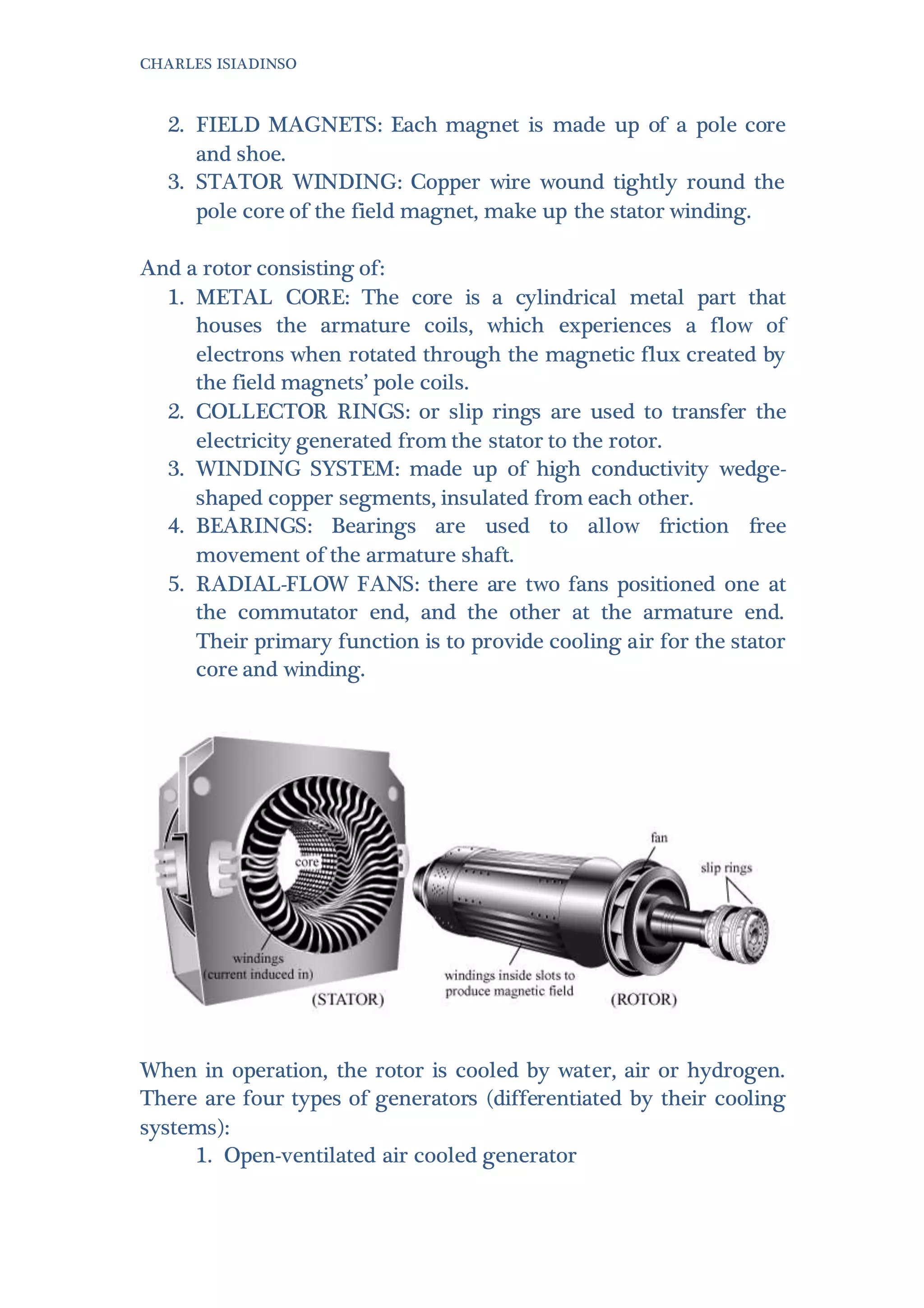
The generator consists of a Stator consisting of a:
1. STATOR CORE: is a silicon steel frame, to which field
magnets are attached.
CHARLES ISIADINSO
2. FIELD MAGNETS: Each magnet is made up of a pole core
and shoe.
3. STATOR WINDING: Copper wire wound tightly round the
pole core of the field magnet, make up the stator winding.
And a rotor consisting of:
1. METAL CORE: The core is a cylindrical metal part that
houses the armature coils, which experiences a flow of
electrons when rotated through the magnetic flux created by
the field magnets’ pole coils.
2. COLLECTOR RINGS: or slip rings are used to transfer the
electricity generated from the stator to the rotor.
3. WINDING SYSTEM: made up of high conductivity wedge-
shaped copper segments, insulated from each other.
4. BEARINGS: Bearings are used to allow friction free
movement of the armature shaft.
5. RADIAL-FLOW FANS: there are two fans positioned one at
the commutator end, and the other at the armature end.
Their primary function is to provide cooling air for the stator
core and winding.
When in operation, the rotor is cooled by water, air or hydrogen.
There are four types of generators (differentiated by their cooling
systems):
1. Open-ventilated air cooled generator
CHARLES ISIADINSO
2. Totally enclosed water to air-cooled (TEWAC) generator
3. Hydrogen-cooledgenerators
4. Water-cooled generators
1. OPEN-VENTILATED AIR COOLED (OV)
GENERATOR:
Outside air is drawn into the generator through a filter system
to remove air contaminants, passed over the rotor, cooling it,
and then discharged back into the surroundings.
2. TEWAC GENERATOR:
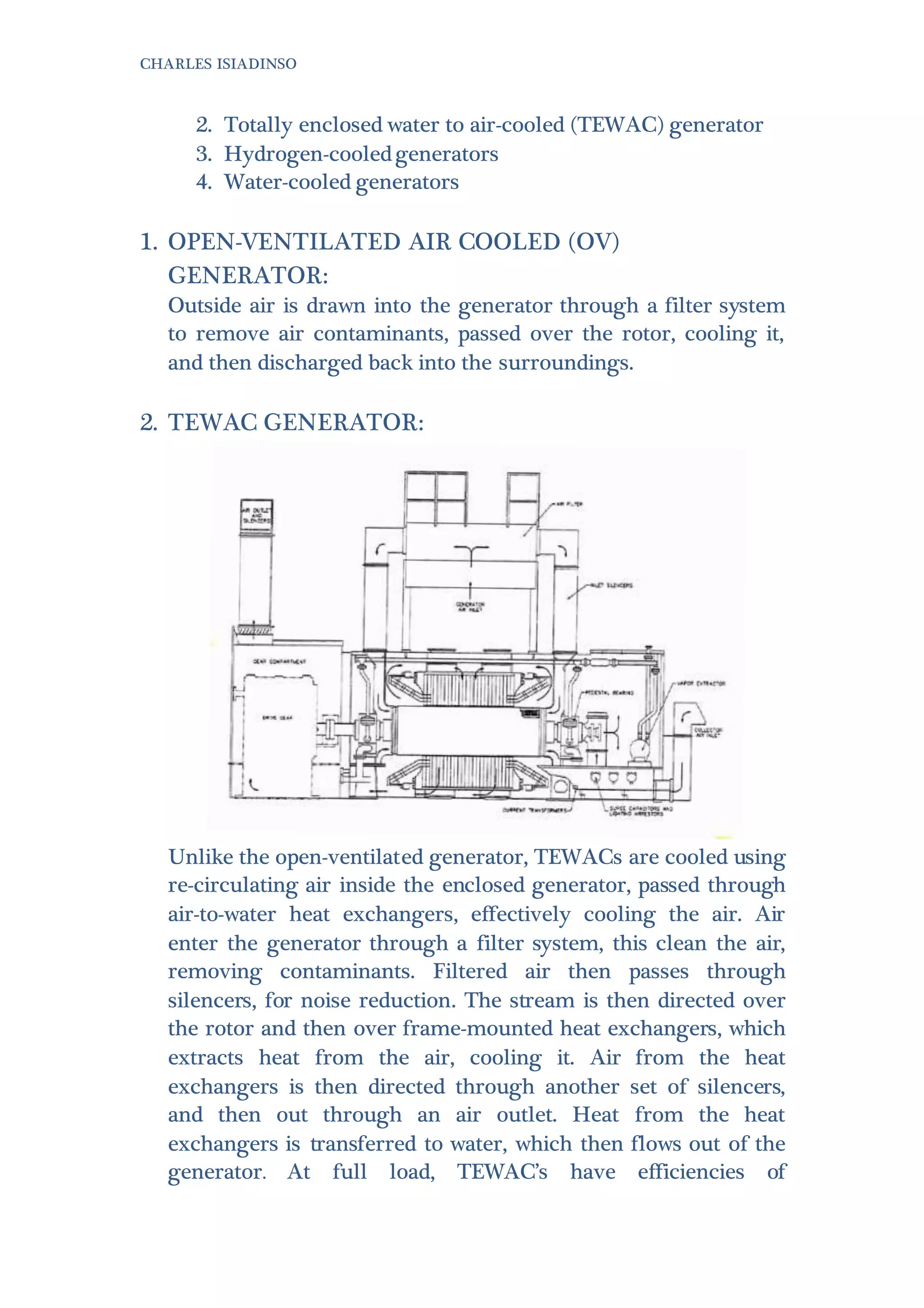
Unlike the open-ventilated generator, TEWACs are cooled using
re-circulating air inside the enclosed generator, passed through
air-to-water heat exchangers, effectively cooling the air. Air
enter the generator through a filter system, this clean the air,
removing contaminants. Filtered air then passes through
silencers, for noise reduction. The stream is then directed over
the rotor and then over frame-mounted heat exchangers, which
extracts heat from the air, cooling it. Air from the heat
exchangers is then directed through another set of silencers,
and then out through an air outlet. Heat from the heat
exchangers is transferred to water, which then flows out of the
generator. At full load, TEWAC’s have efficiencies of
CHARLES ISIADINSO
approximately 98%. TEWAC’s are usually the chosen because of
their reliability and simplicity.
THE EXCITER
Induction generators need current to be present in the stator
windings to work, the process of passing current through the
windings, in order to starts the generator, is called excitation. In a
power station, there is a separate unit (called an exciter) used to
excite the generator. The exciter is also used to control the
generator output. Varying the current supplier to the rotor, which
varies the intensity of the magnetic flux, varies the current induced
in the stator core field magnets.
There are two basic types of exciters, rotating and static exciters.
The exciter maintains an output voltage by directly varying the
amount of excitation as a function of the generator load. There are
a further two types of rotating and static exciters, namely brushed
and brushless excitation systems and shunt and series type
excitation systems respectively. The main difference between the
two rotating systems is the brushed system requires a slip ring,
commutators and brushes and the brushless does not. This
negatively affects the lifetime of the system as the DC voltage
eventually wears out the slip ring. However, the brushless system
are more complicated to design and, as a result, are more
expensive. The difference between the static exciters is the shunt
type operates with power from generator voltage only while the
series type operates from generator voltage and current.
REFERENCE:
1. Kehlhofer, Rolf. Combined-cycle Gas & Steam Turbine Power
Plants. Lilburn, GA: Fairmont, 1991. Print.
CHARLES ISIADINSO
2. "Generators - Air-Cooled Generators | GE Energy." GE
Energy. N.p., n.d. Web. [Accessed17 June 2014].
3. Petchers, Neil. Combined Heating, Cooling & Power
Handbook: Technologies & Applications. Lilburn, GA:
Fairmont, 2003. Print.

More Related Content

What's hot

Thermal Power Plant Simulator, Cold, warm and Hot rolling of Steam Turbine
Thermal Power Plant Simulator, Cold, warm and Hot rolling of Steam TurbineThermal Power Plant Simulator, Cold, warm and Hot rolling of Steam Turbine
Thermal Power Plant Simulator, Cold, warm and Hot rolling of Steam TurbineManohar Tatwawadi
 
Power Plant Simulator Day 3 Part 5
Power Plant Simulator Day 3 Part 5Power Plant Simulator Day 3 Part 5
Power Plant Simulator Day 3 Part 5Manohar Tatwawadi
 
Unit lightup synchronisation & shutdown
Unit lightup synchronisation & shutdownUnit lightup synchronisation & shutdown
Unit lightup synchronisation & shutdownNitin Mahalle
 
Handling of turbine side emergencies
Handling of turbine side emergenciesHandling of turbine side emergencies
Handling of turbine side emergenciesManohar Tatwawadi
 
Steam turbine introduction & maintenance ppt
Steam turbine introduction & maintenance pptSteam turbine introduction & maintenance ppt
Steam turbine introduction & maintenance pptBiswajit Mohanty
 
Steam blowing stages before turbine rolling
Steam blowing stages before turbine rollingSteam blowing stages before turbine rolling
Steam blowing stages before turbine rollingabhinav kumar
 
Boiler Loss of Flame Protection- MFT
Boiler Loss of Flame Protection- MFTBoiler Loss of Flame Protection- MFT
Boiler Loss of Flame Protection- MFTTahoor Alam Khan
 
GE Frame 9E Gas Turbine Nandipur Power Project
GE  Frame 9E Gas Turbine Nandipur Power ProjectGE  Frame 9E Gas Turbine Nandipur Power Project
GE Frame 9E Gas Turbine Nandipur Power ProjectZohaib Asif
 
A presentation on turbogenerator and excitor
A presentation on turbogenerator and excitorA presentation on turbogenerator and excitor
A presentation on turbogenerator and excitorPRAKHAR MEHROTRA
 
210 MW BHEL Turbine Cycle Heat Balance
210 MW BHEL Turbine Cycle Heat Balance210 MW BHEL Turbine Cycle Heat Balance
210 MW BHEL Turbine Cycle Heat BalanceManohar Tatwawadi
 
Scoop coupling
Scoop couplingScoop coupling
Scoop couplingJISHNU V
 
Heat rate audit in thermal power plant
Heat rate audit in thermal power plantHeat rate audit in thermal power plant
Heat rate audit in thermal power plantSHIVAJI CHOUDHURY
 
Steam Turbine Performance in TPS
Steam Turbine Performance in TPSSteam Turbine Performance in TPS
Steam Turbine Performance in TPSManohar Tatwawadi
 
Relief and safety valves for thermal power plants
Relief and safety valves for thermal power plantsRelief and safety valves for thermal power plants
Relief and safety valves for thermal power plantsSHIVAJI CHOUDHURY
 

What's hot (20)

Thermal Power Plant Simulator, Cold, warm and Hot rolling of Steam Turbine
Thermal Power Plant Simulator, Cold, warm and Hot rolling of Steam TurbineThermal Power Plant Simulator, Cold, warm and Hot rolling of Steam Turbine
Thermal Power Plant Simulator, Cold, warm and Hot rolling of Steam Turbine
 
Power Plant Simulator Day 3 Part 5
Power Plant Simulator Day 3 Part 5Power Plant Simulator Day 3 Part 5
Power Plant Simulator Day 3 Part 5
 
Unit lightup synchronisation & shutdown
Unit lightup synchronisation & shutdownUnit lightup synchronisation & shutdown
Unit lightup synchronisation & shutdown
 
Handling of turbine side emergencies
Handling of turbine side emergenciesHandling of turbine side emergencies
Handling of turbine side emergencies
 
Stator water system chemistry
Stator water system chemistryStator water system chemistry
Stator water system chemistry
 
Turbine safety protection
Turbine safety protectionTurbine safety protection
Turbine safety protection
 
Steam turbine introduction & maintenance ppt
Steam turbine introduction & maintenance pptSteam turbine introduction & maintenance ppt
Steam turbine introduction & maintenance ppt
 
Steam blowing stages before turbine rolling
Steam blowing stages before turbine rollingSteam blowing stages before turbine rolling
Steam blowing stages before turbine rolling
 
Turbo generator & its auxiliaries
Turbo generator & its auxiliariesTurbo generator & its auxiliaries
Turbo generator & its auxiliaries
 
Boiler Loss of Flame Protection- MFT
Boiler Loss of Flame Protection- MFTBoiler Loss of Flame Protection- MFT
Boiler Loss of Flame Protection- MFT
 
GE Frame 9E Gas Turbine Nandipur Power Project
GE  Frame 9E Gas Turbine Nandipur Power ProjectGE  Frame 9E Gas Turbine Nandipur Power Project
GE Frame 9E Gas Turbine Nandipur Power Project
 
coal pulveriser
coal pulveriser coal pulveriser
coal pulveriser
 
A presentation on turbogenerator and excitor
A presentation on turbogenerator and excitorA presentation on turbogenerator and excitor
A presentation on turbogenerator and excitor
 
TURBINE FUNDAMENTAL
TURBINE FUNDAMENTALTURBINE FUNDAMENTAL
TURBINE FUNDAMENTAL
 
210 MW BHEL Turbine Cycle Heat Balance
210 MW BHEL Turbine Cycle Heat Balance210 MW BHEL Turbine Cycle Heat Balance
210 MW BHEL Turbine Cycle Heat Balance
 
Scoop coupling
Scoop couplingScoop coupling
Scoop coupling
 
Heat rate audit in thermal power plant
Heat rate audit in thermal power plantHeat rate audit in thermal power plant
Heat rate audit in thermal power plant
 
FAQ on Turbines Part 2
FAQ on Turbines Part 2FAQ on Turbines Part 2
FAQ on Turbines Part 2
 
Steam Turbine Performance in TPS
Steam Turbine Performance in TPSSteam Turbine Performance in TPS
Steam Turbine Performance in TPS
 
Relief and safety valves for thermal power plants
Relief and safety valves for thermal power plantsRelief and safety valves for thermal power plants
Relief and safety valves for thermal power plants
 

Similar to 2. Tewac Generator

Similar to 2. Tewac Generator (20)

5.2.c gen basics
5.2.c gen basics5.2.c gen basics
5.2.c gen basics
 
Alternator wikipedia, the free encyclopedia
Alternator   wikipedia, the free encyclopediaAlternator   wikipedia, the free encyclopedia
Alternator wikipedia, the free encyclopedia
 
Dc & ac motors
Dc & ac motorsDc & ac motors
Dc & ac motors
 
Induction motor
Induction motorInduction motor
Induction motor
 
Chap41
Chap41Chap41
Chap41
 
Chapter 41
Chapter 41Chapter 41
Chapter 41
 
Ch10
Ch10Ch10
Ch10
 
Wapda Umair Report
Wapda Umair ReportWapda Umair Report
Wapda Umair Report
 
16575553 ac-motor
16575553 ac-motor16575553 ac-motor
16575553 ac-motor
 
AC generator
AC generatorAC generator
AC generator
 
SCIENCE 10-LESSON 11hatdogtinapaitlog.pdf
SCIENCE 10-LESSON 11hatdogtinapaitlog.pdfSCIENCE 10-LESSON 11hatdogtinapaitlog.pdf
SCIENCE 10-LESSON 11hatdogtinapaitlog.pdf
 
Transformers and its Types
Transformers and its TypesTransformers and its Types
Transformers and its Types
 
Repulsive Gen-co
Repulsive Gen-coRepulsive Gen-co
Repulsive Gen-co
 
SYNCHRONOUS MOTOR
SYNCHRONOUS MOTORSYNCHRONOUS MOTOR
SYNCHRONOUS MOTOR
 
Ac generator
Ac generatorAc generator
Ac generator
 
TRANSFORMER.pptx
TRANSFORMER.pptxTRANSFORMER.pptx
TRANSFORMER.pptx
 
What is an electric motor.pptx
What is an electric motor.pptxWhat is an electric motor.pptx
What is an electric motor.pptx
 
Module 5.pptx
Module 5.pptxModule 5.pptx
Module 5.pptx
 
Kings Transformer types
Kings  Transformer typesKings  Transformer types
Kings Transformer types
 
Salman salu electrical
Salman salu electricalSalman salu electrical
Salman salu electrical
 

More from Chinedu Isiadinso

More from Chinedu Isiadinso (10)

CW1 Report
CW1 ReportCW1 Report
CW1 Report
 
6. Balance Of Plant
6. Balance Of Plant6. Balance Of Plant
6. Balance Of Plant
 
Heat exchanger design project
Heat exchanger design project Heat exchanger design project
Heat exchanger design project
 
BP Texas City Refinery Disaster Report
BP Texas City Refinery Disaster ReportBP Texas City Refinery Disaster Report
BP Texas City Refinery Disaster Report
 
7. Transmission Lines
7. Transmission Lines7. Transmission Lines
7. Transmission Lines
 
5. Switchyard & Substation
5. Switchyard & Substation5. Switchyard & Substation
5. Switchyard & Substation
 
4. Generator Step Up Transformer
4. Generator Step Up Transformer4. Generator Step Up Transformer
4. Generator Step Up Transformer
 
Renewable Energy Essay
Renewable Energy EssayRenewable Energy Essay
Renewable Energy Essay
 
POWER TRANSMISSION IN ENGINES
POWER TRANSMISSION IN ENGINESPOWER TRANSMISSION IN ENGINES
POWER TRANSMISSION IN ENGINES
 
1. Gas Turbine (9E03)
1. Gas Turbine (9E03)1. Gas Turbine (9E03)
1. Gas Turbine (9E03)
 

2. Tewac Generator

  • 1. CHARLES ISIADINSO TOTALLY ENCLOSED WATER TO AIR COOLED (TEWAC) GENERATOR THE GENERATOR In a power plant, electricity is generated by the generator, which works on Faraday’s law of electromagnetic induction. A turbine (steam or gas) turns shaft to which a rotor is attached. The rotor spins in a gap in a part called the stator. The law of electromagnetic induction states that if a magnet is rotated close to a conductor (e.g. copper wire), a current is induced in the conductor. To vary the strength of the magnetic flux, the rotor is an electromagnet (a magnet with windings of a conductor around it) rotating inside the stator, which is a toothed metal ring shaped structure with coils of a conductor between the teeth. To start the process, current (excitation current) is passed into the conductor coils of the rotor; this creates a magnetic flux in the air gap between the rotor and stator. This magnetic flux then induces a flow of electrons (current) in the stator coil thus generating electricity. In some turbine systems, the generator is used to start the turbine. An exciter module, which contains the generator excitation system and start-up frequency converter (SFC) start system, starts the gas turbine by temporarily converting the generator into a motor, using the SFC. However, with GE’s 9E gas turbine, a separate staring motor is used. The generator is connected to the 9E after the exhaust system by a rigid metal shaft that runs through the entire turbine and into the generator, and is what the generator rotor is attached to. Rotation of the air compressor and turbine blades causes a rotation in the shaft, which then rotates the rotor in the stator, generating electricity. The generator consists of a Stator consisting of a: 1. STATOR CORE: is a silicon steel frame, to which field magnets are attached.
  • 2. CHARLES ISIADINSO 2. FIELD MAGNETS: Each magnet is made up of a pole core and shoe. 3. STATOR WINDING: Copper wire wound tightly round the pole core of the field magnet, make up the stator winding. And a rotor consisting of: 1. METAL CORE: The core is a cylindrical metal part that houses the armature coils, which experiences a flow of electrons when rotated through the magnetic flux created by the field magnets’ pole coils. 2. COLLECTOR RINGS: or slip rings are used to transfer the electricity generated from the stator to the rotor. 3. WINDING SYSTEM: made up of high conductivity wedge- shaped copper segments, insulated from each other. 4. BEARINGS: Bearings are used to allow friction free movement of the armature shaft. 5. RADIAL-FLOW FANS: there are two fans positioned one at the commutator end, and the other at the armature end. Their primary function is to provide cooling air for the stator core and winding. When in operation, the rotor is cooled by water, air or hydrogen. There are four types of generators (differentiated by their cooling systems): 1. Open-ventilated air cooled generator
  • 3. CHARLES ISIADINSO 2. Totally enclosed water to air-cooled (TEWAC) generator 3. Hydrogen-cooledgenerators 4. Water-cooled generators 1. OPEN-VENTILATED AIR COOLED (OV) GENERATOR: Outside air is drawn into the generator through a filter system to remove air contaminants, passed over the rotor, cooling it, and then discharged back into the surroundings. 2. TEWAC GENERATOR: Unlike the open-ventilated generator, TEWACs are cooled using re-circulating air inside the enclosed generator, passed through air-to-water heat exchangers, effectively cooling the air. Air enter the generator through a filter system, this clean the air, removing contaminants. Filtered air then passes through silencers, for noise reduction. The stream is then directed over the rotor and then over frame-mounted heat exchangers, which extracts heat from the air, cooling it. Air from the heat exchangers is then directed through another set of silencers, and then out through an air outlet. Heat from the heat exchangers is transferred to water, which then flows out of the generator. At full load, TEWAC’s have efficiencies of
  • 4. CHARLES ISIADINSO approximately 98%. TEWAC’s are usually the chosen because of their reliability and simplicity. THE EXCITER Induction generators need current to be present in the stator windings to work, the process of passing current through the windings, in order to starts the generator, is called excitation. In a power station, there is a separate unit (called an exciter) used to excite the generator. The exciter is also used to control the generator output. Varying the current supplier to the rotor, which varies the intensity of the magnetic flux, varies the current induced in the stator core field magnets. There are two basic types of exciters, rotating and static exciters. The exciter maintains an output voltage by directly varying the amount of excitation as a function of the generator load. There are a further two types of rotating and static exciters, namely brushed and brushless excitation systems and shunt and series type excitation systems respectively. The main difference between the two rotating systems is the brushed system requires a slip ring, commutators and brushes and the brushless does not. This negatively affects the lifetime of the system as the DC voltage eventually wears out the slip ring. However, the brushless system are more complicated to design and, as a result, are more expensive. The difference between the static exciters is the shunt type operates with power from generator voltage only while the series type operates from generator voltage and current. REFERENCE: 1. Kehlhofer, Rolf. Combined-cycle Gas & Steam Turbine Power Plants. Lilburn, GA: Fairmont, 1991. Print.
  • 5. CHARLES ISIADINSO 2. "Generators - Air-Cooled Generators | GE Energy." GE Energy. N.p., n.d. Web. [Accessed17 June 2014]. 3. Petchers, Neil. Combined Heating, Cooling & Power Handbook: Technologies & Applications. Lilburn, GA: Fairmont, 2003. Print.