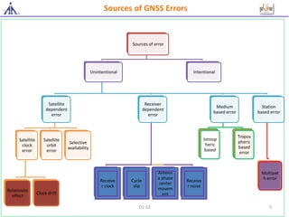
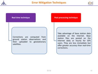
GNSS Errors, Sources and Mitigation Techniques
1D1-S3
Topics to be Covered/Objectives
Introduction to GNSS Errors
Sources of Errors
Error mitigation techniques
D1-S3 2
At the end of this session, trainee will be able to:
Describe various sources of GNSS errors
Explain the mitigation techniques of GNSS errors
3D1-S3
Introduction to GNSS Errors
GPS to GLONASS and Galileo has intrinsic error sources that have to be taken into
account when a receiver reads the GNSS signals from the constellation of satellites in
orbit.
A GNSS receiver measures the apparent transit time(Pseudo range) of the satellite
signal from the satellite to the user. Pseudo range consists of the propagation delay and
receiver clock bias.
For the accurate user position calculation following parameters plays important role:
 1) Time of transmission
 2) Time of Reception
 3) Satellite signal propagation medium
 4) Position of satellites
Introduction to GNSS Errors
D1-S3 4
Sources of error
Unintentional
Satellite
dependent
error
Satellite
clock
error
Relativistic
effect
Clock drift
Satellite
orbit
error
Selective
availability
Receiver
dependent
error
Receive
r clock
Cycle
slip
Antenn
a phase
center
movem
ent
Receive
r noise
Medium
based error
Ionosp
heric
based
Tropos
pheric
based
error
Station
based error
Multipat
h error
Intentional
Sources of GNSS Errors
D1-S3 5
Satellite Clock Errors
• First effect:
the frequency is set a bit slow before launch (10.22999999545 MHz).
• Second effect:
It is attributable to eccentricity (0.02) of orbit causing time error of 45.8
ns. This error is corrected in GPS receiver itself avoiding an error of about
14 m.
Relativistic effect : Clock in orbit will appear to run faster than
on earth
• Rubidium clocks: 1 to 2 parts in 1013 over a period of one day or about
8.64 to 17.28 ns per day
• Caesium clocks: stability improves to 1 to 2 parts in 1014 over 10 days
• Hydrogen masers: 1 part in 1014.
• Unavoidable temporally variant clock errors are source of a significant
bias which are monitored by the control segment during tracking data
analysis
Clock drift: Stability of GPS clocks:
D1-S3 6
Unintentional Errors
Satellite
Orbit/
Ephemeris
Errors
Receiver
Dependent
Error
D1-S3 7
Ionospheric Based Error
The ionosphere regions can absorb or dampen radio signals, or they can bend radio waves, as well as
reflecting the signals.
The specific behaviour depends on both the frequency of the radio signal as well as the characteristics
of the ionosphere region involved.
Scientists constantly measure and produce computer models of the ever-changing ionosphere so that
people in charge of radio communications can anticipate disruptions.
Medium Based Error
Ionospheric Models for Single Frequency Receivers
1.Single frequency receivers need to apply a model to remove the ionospheric refraction which
can reach up to few tens of meters, depending on the elevation of rays and the ionospheric
conditions
The models used in GPS and Gallileo are described in klobuchar model, and NeQuick Model. The
GPS/Galileo satellites broadcast the parameters needed to run these ionospheric models.
In GLONAS, there is no ionospheric model applied and thus, there is no broadcast of any
parameter. However, any of the GPS or GALILEO ionospheric models could be used for GLONASS
signals, by applying a correction factor given by their relative squared frequencies ratio.
AAI-ISRO developed IONO model, known as IMLDF (Indian Multi Layer Data Fusion) which is
capable to correct IONO errors over Indian airspace.
D1-S3 8
MLDF Model
 IGM-MLDF employs innovative scheme of modelling at two shell heights.
Through empirical analysis the shell heights of 250 km and 450 km are chosen.
The ionosphere measurement source for these two shells is obtained
through a novel idea of utilizing both the Indian reference equipment's
(INREEs) residing at each of INRESs
Kriging algorithm is applied to compute the grid vertical delay error and
error estimates at the IGP in the designated shell heights
A new approach of data fusion is applied at the vertical IGPs to fuse delays
and confidences at 350 km shell height
Ionosphere storm detection algorithm utilizes goodness of fit test to protect
the user from irregular behaviour of ionosphere
Ionospheric Based Error
D1-S3 9
Medium Based Error
Troposphere Based Error
This delay depends on the temperature, pressure, humidity as well as the
transmitter and receiver antennas location
Tropospheric effects are not frequency dependent for the GNSS signals. Hence,
the carrier phase and code measurements are affected by the same delay
The only way to mitigate tropospheric effect is to use models and/or to estimate
it from observational data
Troposphere can be successfully modelled using the values of temperature,
pressure and relative humidity and satellite elevation angle
D1-S3 10
Station Based Error
Multipath Error
The interference by multipath is generated when a signal arrives, by different ways, at the antenna
Its principal cause is the antenna closeness to the reflecting structures.
This error is different for different frequencies. It affects the phase measurements, as well as the code
measurements
The Multipath Estimating Delay-Lock-Loop (MEDLL) isa method for mitigating the effects due to multipath
within the receiver tracking loops.
The MEDLL does this by separating the signal into its line-of-sight and multipath components
The multipath signal will always arrive after the direct path signal
The MEDLL estimates the amplitude, delay, and phase of each multipath component using maximum
likelihood criteria.
D1-S3 11
Unintentional Error
Jamming directed at non-aviation users
DME: as it shares a frequency band with GNSS
Spoofing
GNSS repeaters and pseudo-lites
Unintentional Error
Spectrum Regulation
States should prohibit all actions that lead to disruption of GNSS signals and
should develop and enforce a strong regulatory framework governing the use of
intentional in-band radiators, including GNSS repeaters, pseudo-lites, spoofers and
jammers.
D1-S3 12
Error Mitigation Techniques
Real time technique
Corrections are computed from
ground station observations and
then uploaded to geostationary
satellites.
Post processing technique
Take advantage of base station data
available on the Internet. Base
station files are posted on the
Internet daily or hourly for GPS
users. They are less immediate but
offer greater accuracy than real-time
corrections.
D1-S3 13
Questions?
D1-S3 14
Thank You
D1-S3 15

#2 gnss errors,its sources & mitigation techniques

  • 1.
    GNSS Errors, Sourcesand Mitigation Techniques 1D1-S3
  • 2.
    Topics to beCovered/Objectives Introduction to GNSS Errors Sources of Errors Error mitigation techniques D1-S3 2
  • 3.
    At the endof this session, trainee will be able to: Describe various sources of GNSS errors Explain the mitigation techniques of GNSS errors 3D1-S3
  • 4.
    Introduction to GNSSErrors GPS to GLONASS and Galileo has intrinsic error sources that have to be taken into account when a receiver reads the GNSS signals from the constellation of satellites in orbit. A GNSS receiver measures the apparent transit time(Pseudo range) of the satellite signal from the satellite to the user. Pseudo range consists of the propagation delay and receiver clock bias. For the accurate user position calculation following parameters plays important role:  1) Time of transmission  2) Time of Reception  3) Satellite signal propagation medium  4) Position of satellites Introduction to GNSS Errors D1-S3 4
  • 5.
    Sources of error Unintentional Satellite dependent error Satellite clock error Relativistic effect Clockdrift Satellite orbit error Selective availability Receiver dependent error Receive r clock Cycle slip Antenn a phase center movem ent Receive r noise Medium based error Ionosp heric based Tropos pheric based error Station based error Multipat h error Intentional Sources of GNSS Errors D1-S3 5
  • 6.
    Satellite Clock Errors •First effect: the frequency is set a bit slow before launch (10.22999999545 MHz). • Second effect: It is attributable to eccentricity (0.02) of orbit causing time error of 45.8 ns. This error is corrected in GPS receiver itself avoiding an error of about 14 m. Relativistic effect : Clock in orbit will appear to run faster than on earth • Rubidium clocks: 1 to 2 parts in 1013 over a period of one day or about 8.64 to 17.28 ns per day • Caesium clocks: stability improves to 1 to 2 parts in 1014 over 10 days • Hydrogen masers: 1 part in 1014. • Unavoidable temporally variant clock errors are source of a significant bias which are monitored by the control segment during tracking data analysis Clock drift: Stability of GPS clocks: D1-S3 6
  • 7.
  • 8.
    Ionospheric Based Error Theionosphere regions can absorb or dampen radio signals, or they can bend radio waves, as well as reflecting the signals. The specific behaviour depends on both the frequency of the radio signal as well as the characteristics of the ionosphere region involved. Scientists constantly measure and produce computer models of the ever-changing ionosphere so that people in charge of radio communications can anticipate disruptions. Medium Based Error Ionospheric Models for Single Frequency Receivers 1.Single frequency receivers need to apply a model to remove the ionospheric refraction which can reach up to few tens of meters, depending on the elevation of rays and the ionospheric conditions The models used in GPS and Gallileo are described in klobuchar model, and NeQuick Model. The GPS/Galileo satellites broadcast the parameters needed to run these ionospheric models. In GLONAS, there is no ionospheric model applied and thus, there is no broadcast of any parameter. However, any of the GPS or GALILEO ionospheric models could be used for GLONASS signals, by applying a correction factor given by their relative squared frequencies ratio. AAI-ISRO developed IONO model, known as IMLDF (Indian Multi Layer Data Fusion) which is capable to correct IONO errors over Indian airspace. D1-S3 8
  • 9.
    MLDF Model  IGM-MLDFemploys innovative scheme of modelling at two shell heights. Through empirical analysis the shell heights of 250 km and 450 km are chosen. The ionosphere measurement source for these two shells is obtained through a novel idea of utilizing both the Indian reference equipment's (INREEs) residing at each of INRESs Kriging algorithm is applied to compute the grid vertical delay error and error estimates at the IGP in the designated shell heights A new approach of data fusion is applied at the vertical IGPs to fuse delays and confidences at 350 km shell height Ionosphere storm detection algorithm utilizes goodness of fit test to protect the user from irregular behaviour of ionosphere Ionospheric Based Error D1-S3 9
  • 10.
    Medium Based Error TroposphereBased Error This delay depends on the temperature, pressure, humidity as well as the transmitter and receiver antennas location Tropospheric effects are not frequency dependent for the GNSS signals. Hence, the carrier phase and code measurements are affected by the same delay The only way to mitigate tropospheric effect is to use models and/or to estimate it from observational data Troposphere can be successfully modelled using the values of temperature, pressure and relative humidity and satellite elevation angle D1-S3 10
  • 11.
    Station Based Error MultipathError The interference by multipath is generated when a signal arrives, by different ways, at the antenna Its principal cause is the antenna closeness to the reflecting structures. This error is different for different frequencies. It affects the phase measurements, as well as the code measurements The Multipath Estimating Delay-Lock-Loop (MEDLL) isa method for mitigating the effects due to multipath within the receiver tracking loops. The MEDLL does this by separating the signal into its line-of-sight and multipath components The multipath signal will always arrive after the direct path signal The MEDLL estimates the amplitude, delay, and phase of each multipath component using maximum likelihood criteria. D1-S3 11
  • 12.
    Unintentional Error Jamming directedat non-aviation users DME: as it shares a frequency band with GNSS Spoofing GNSS repeaters and pseudo-lites Unintentional Error Spectrum Regulation States should prohibit all actions that lead to disruption of GNSS signals and should develop and enforce a strong regulatory framework governing the use of intentional in-band radiators, including GNSS repeaters, pseudo-lites, spoofers and jammers. D1-S3 12
  • 13.
    Error Mitigation Techniques Realtime technique Corrections are computed from ground station observations and then uploaded to geostationary satellites. Post processing technique Take advantage of base station data available on the Internet. Base station files are posted on the Internet daily or hourly for GPS users. They are less immediate but offer greater accuracy than real-time corrections. D1-S3 13
  • 14.
  • 15.