

More Related Content
What's hot
Viewers also liked
Viewers also liked (14)
Recently uploaded
Recently uploaded (7)
แบบฝึกหัดที่ 2 การเตรียมอุปกรณ์
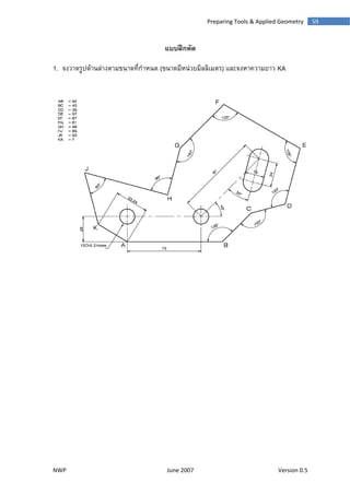
- 1. NW 1. จ P จงวาดรูปดานนลางตามขนนาดที่กําหนด June 200 แบบฝกหั (ขนาดมีหน 07 Prepa หัด นวยมิลลิเมตร aring Tools & ร) และจงหาค Ve & Applied Ge ความยาว KA ersion 0.5 59ometry A 9
- 2. NWP June 2007 Version 0.5 60 Fundamental of Engineering Drawing 2. จงวาดรูปดานลางตามขนาดที่กําหนด
- 3. NWP June 2007 Version 0.5 61 Preparing Tools & Applied Geometry 3. จงวาดรูปดานลางตามขนาดที่กําหนด
- 4. NWP June 2007 Version 0.5 62 Fundamental of Engineering Drawing 4. จงวาดรูปดานลางตามขนาดที่กําหนด