Download to read offline
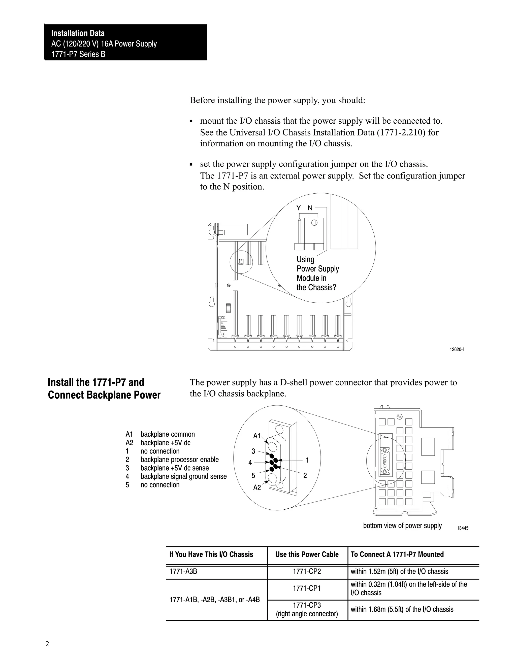
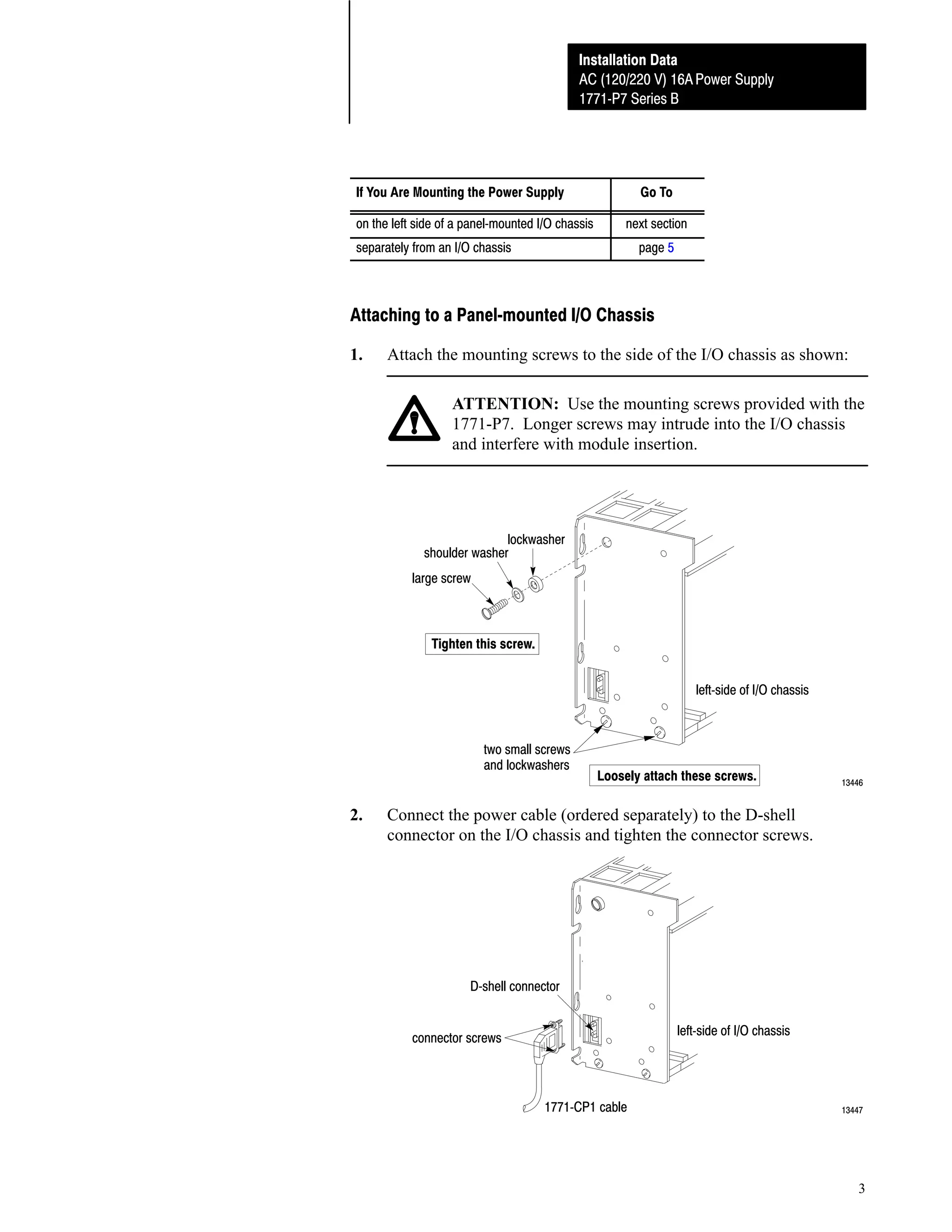
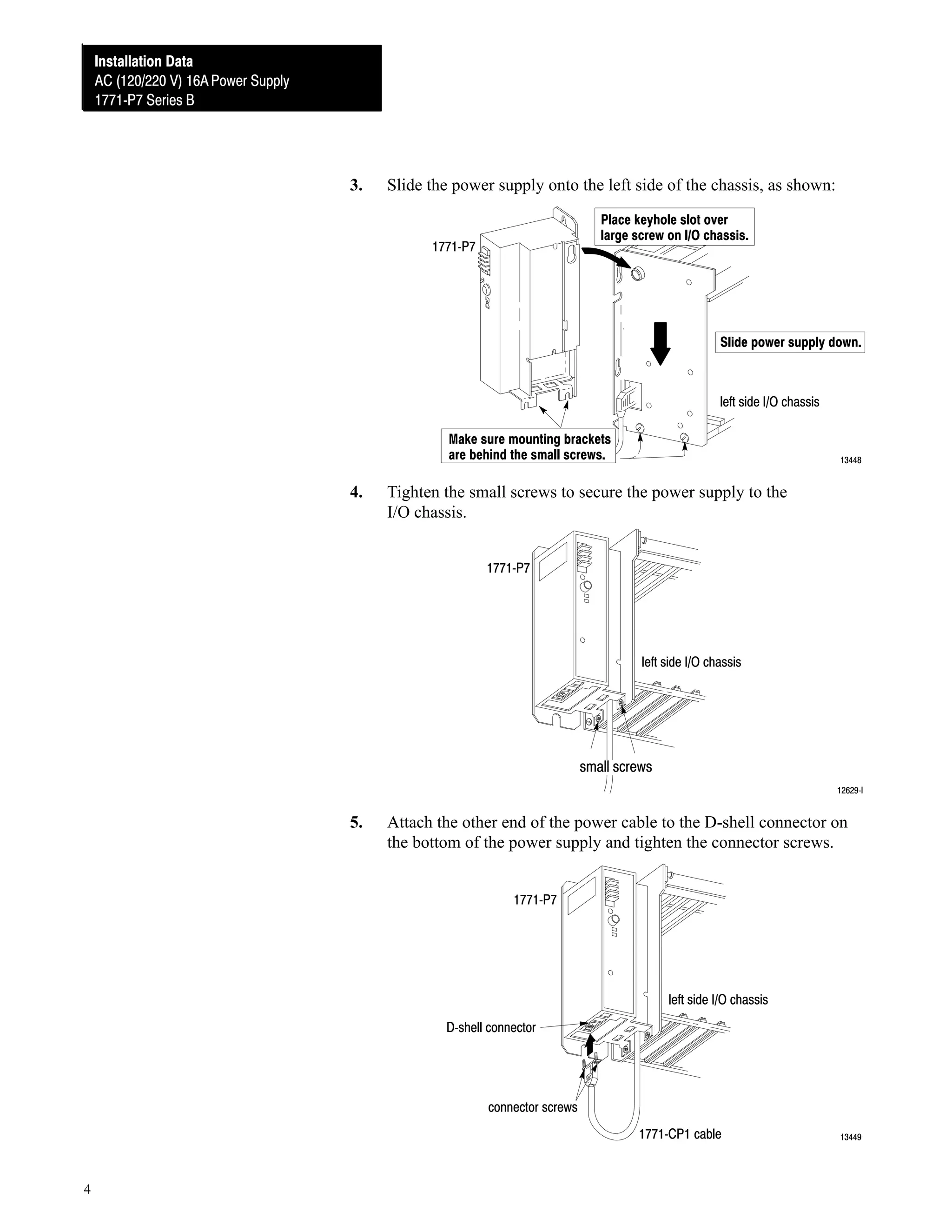
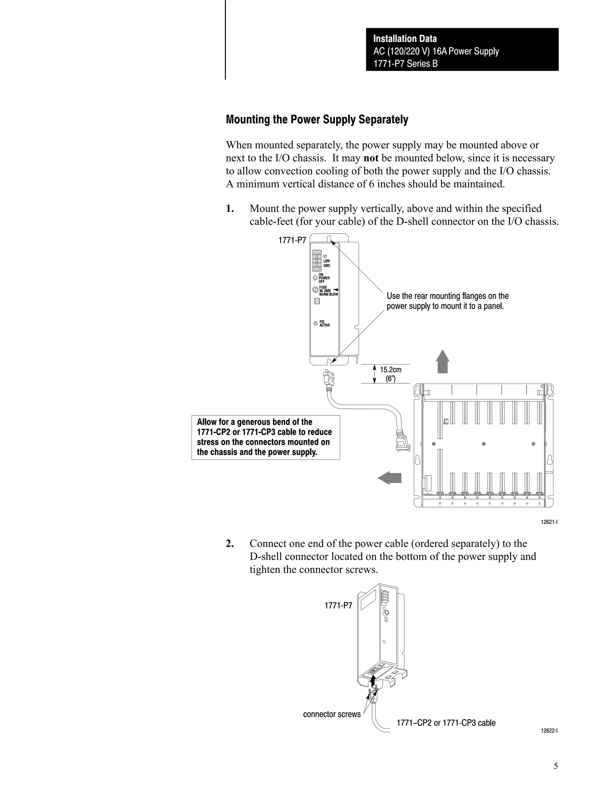
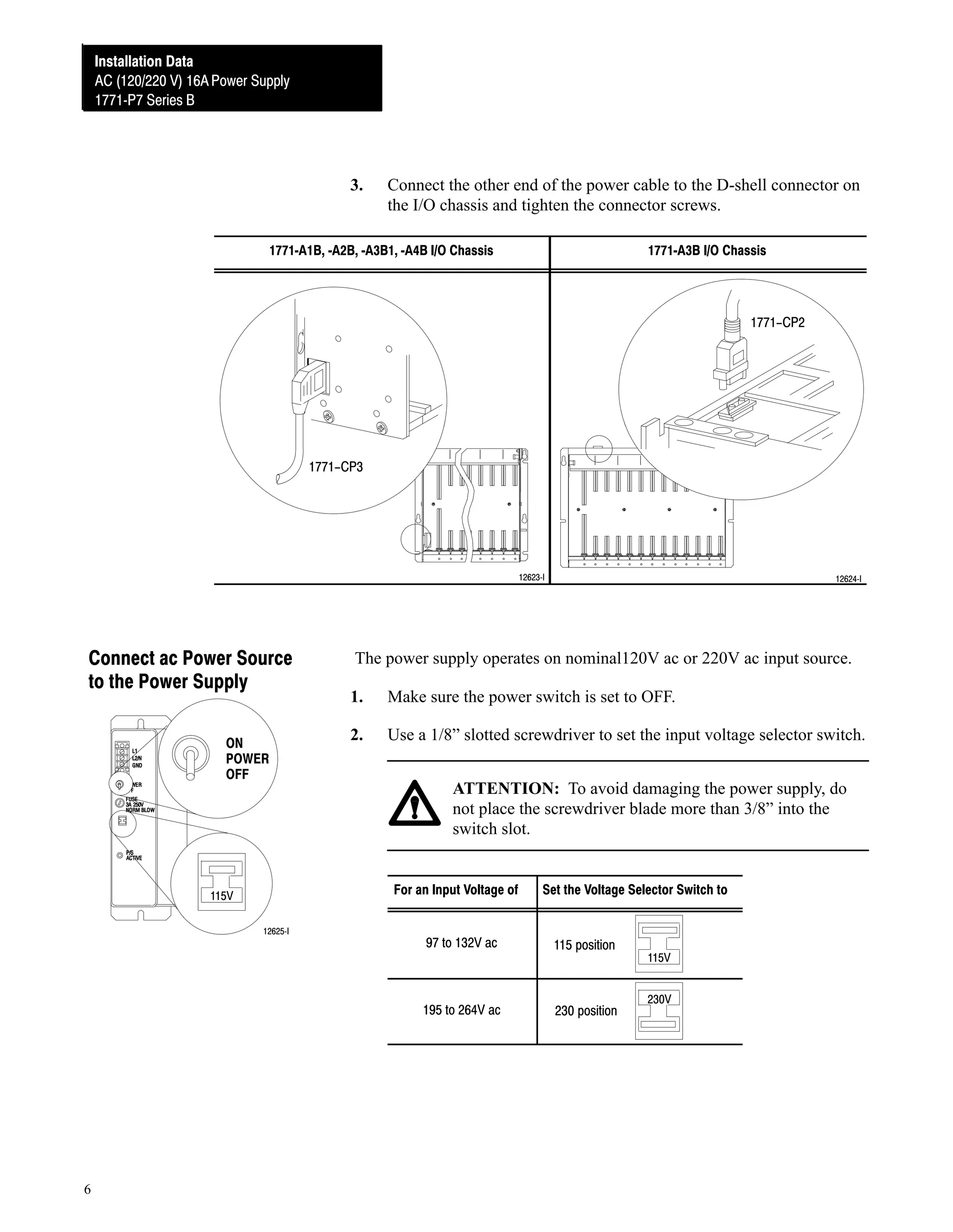
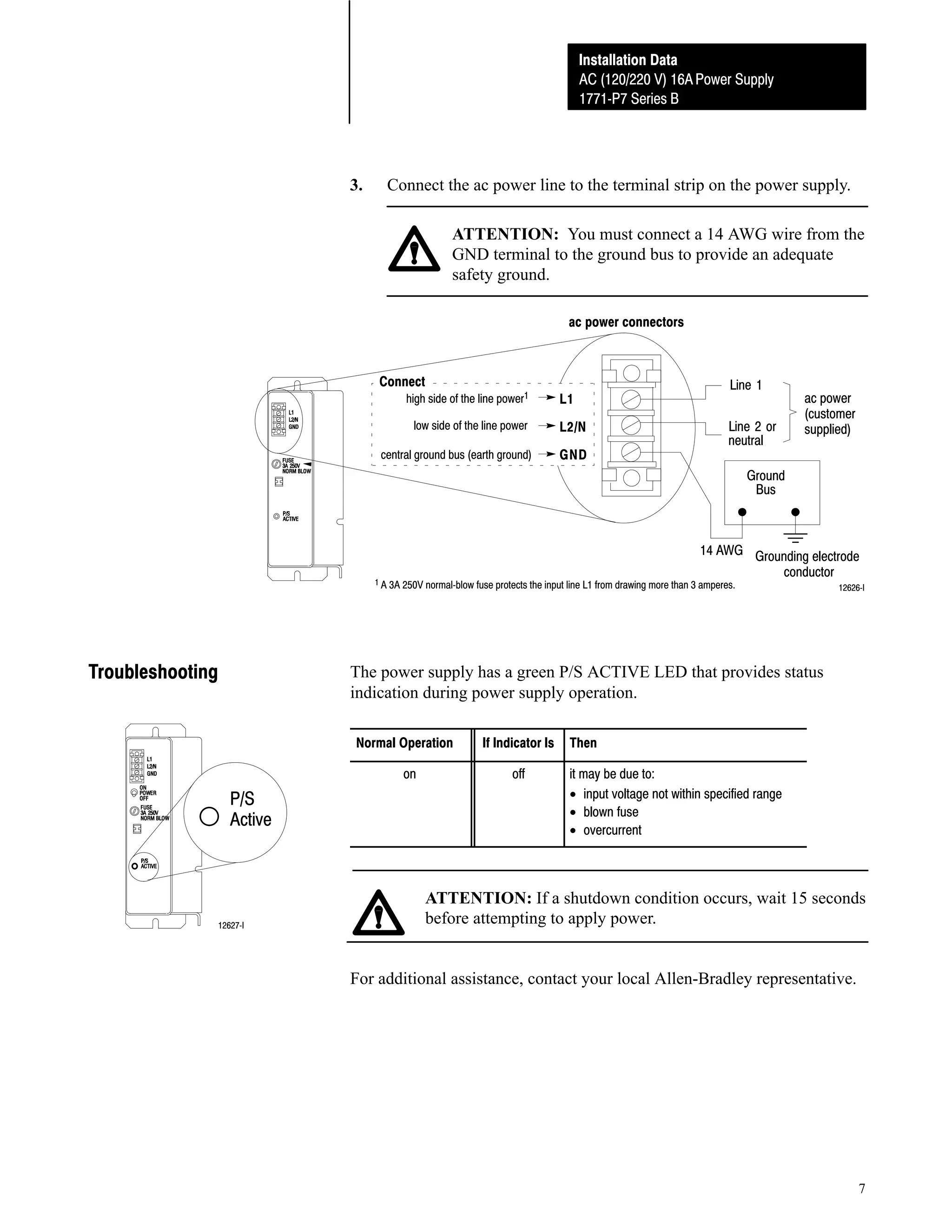
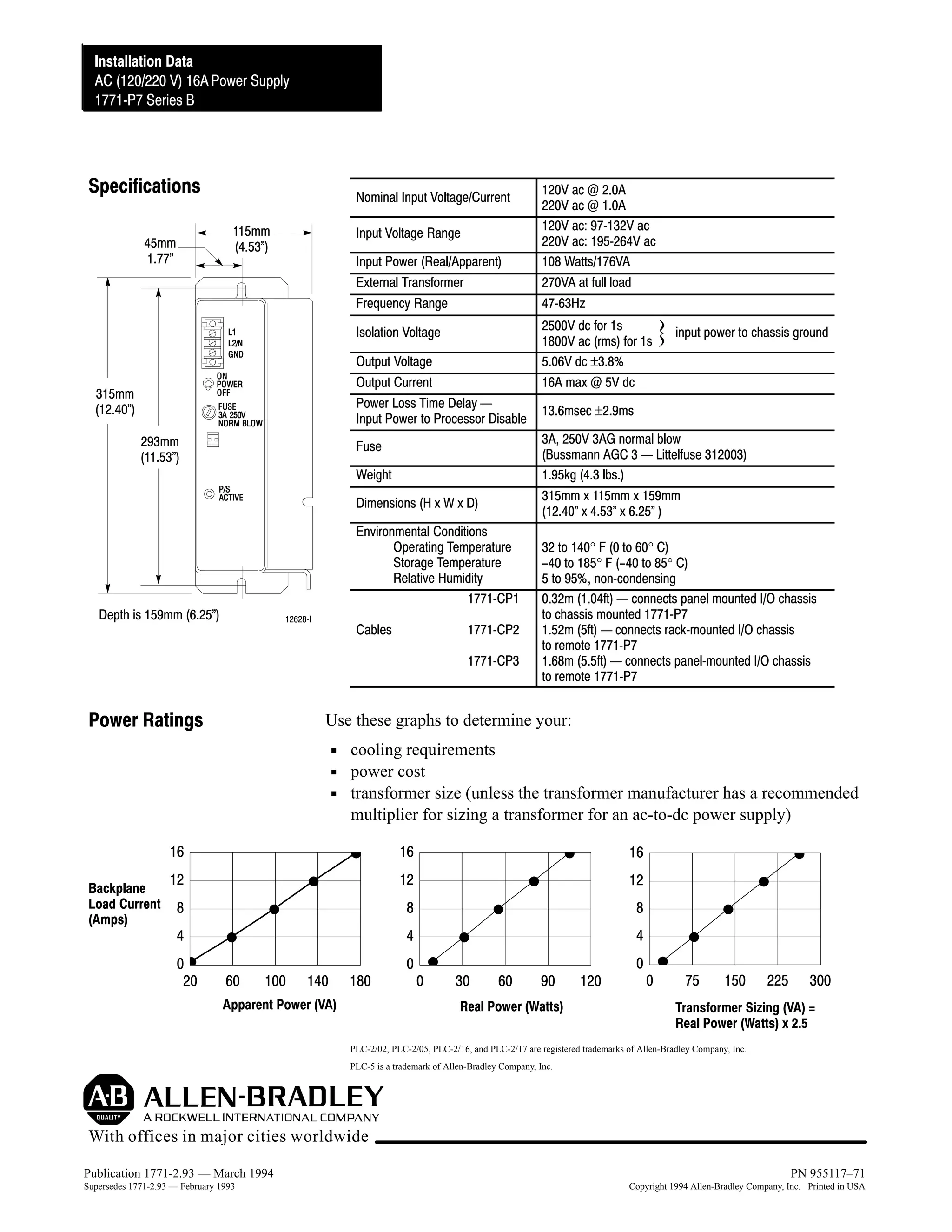

The document provides installation instructions for an AC (120/220V) 16A power supply (Cat. No. 1771-P7 Series B). It describes how to prepare for installation, install the power supply, connect AC power, troubleshoot issues, and lists specifications. The power supply can power one 1771-A1B, -A2B, -A3B, -A3B1, or -A4B I/O chassis when used with compatible programmable controllers or adapter modules.


