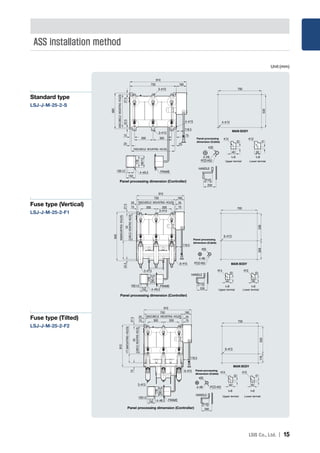
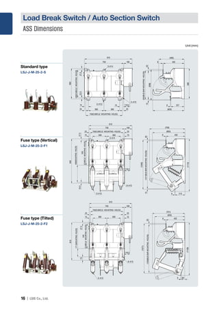
The document provides information on 24 kV load break switches and 25.8 kV auto section switches. It includes sections on features, structure and function, ratings, control circuits, installation methods, and dimensions. Key points are compact, lightweight designs with excellent blocking performance for safety and reliability in hot-line operation. Manual and electric options are available with short time current ratings up to 25 kA/1 second and making/breaking capacities up to 900A.
![4 I
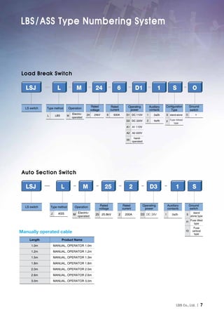
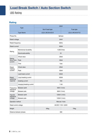
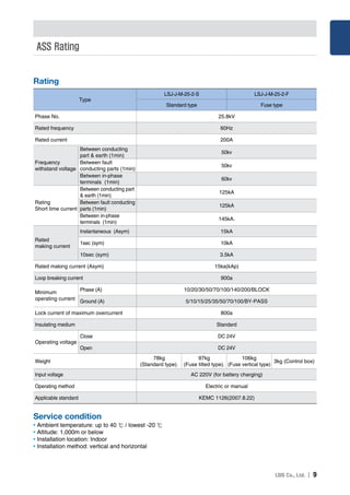
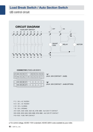
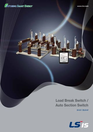
Load Break Switch / Auto Section Switch
High technology
• Realization of compact and lightweight for user
convenience
• Lightning Impulse type with puffer structure that has
excellent blocking performance
• Easy maintenance
• Fuses up to 100A can be applied
Safety
• Safe operation in hot-line status
• Obvious visual check for ON-OFF status
• Perfect fuse striker structure
High reliability and convenience
• Maximizing arc extinguishing capability by
compressed air
• Vertical and horizontal installation features
• Manual cable with distance adjustment
• Remote operation function.
• Provide an alarm contact in case of fuse cut-off
Grounding switch function
• 25kA/1 second short time capability
• Maximize safety through interlock device for main
circuit and ground switch
Load Break Switch
[Feature]
Basic type
Fuse adhesive type
24kV Power FUSE](https://image.slidesharecdn.com/161122lbsasse-170815210153/85/161122-lbs-ass_e-4-320.jpg)
![I 5
Manually operated cable
• Standard length is 2m and 2.6m. Custom-made,
1.2m, 5m should be discussed separately.
• Turn the the hand wheel to the right for 50 times and
manual input is completed, while turn it to the same
direction for 8 times, the opening operation is completed.
Load Break Switch
[Structure]
➏
➐
➒
➑
➊ ➋ ➌ ➍ ➎
➊ Arc blade
➋ Main movable part
➌ Arc extinguish part
➍ Primary terminal
➎ Operation mechanism
➏ Fuse holder
➐ Fuse
➑ Secondary terminal
➒ Insulation support
LBS structure](https://image.slidesharecdn.com/161122lbsasse-170815210153/85/161122-lbs-ass_e-5-320.jpg)
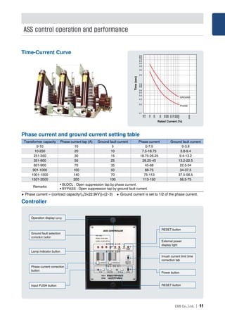
![6 I
inrush current suppression
• When ASS operates normally (if current is 10%
100% current correction tab), blocks opening
operation and it is put into operation again, this
function suppresses malfunction of which ASS
mistakes the current as a fault current due to inrush
current of backup protective equipment of ASS.
Overload protection
• It is operate according to the inverse characteristic
curve in less than an overcurrent lock of 800A.
Stored energy Trip
• Although blocking is operated according to the T-C
curve due to overload or ASS is not blocked since the
overload is removed, if backup protective equipment
is operated so that no voltage is generated, the ASS
will be instantaneously released and disconnects line
of back of the ASS.
Overcurrent lock
• While ASS protects the switching when failure of rated
breaking current (900A) occurs, if the current is greater
than the lock current (800A ± 10%), the switch will
be LOCK status. The fault current will be removed
by the backup protective equipment and ASS will be
blocked in the non-voltage status.
➊
➋
➏
➌
➎ ➍
➑ ➒ ➓➐
[Structure]
[Feature]
Control box
Auto Section Switch
➊ Arc extinguish part
➋ Primary terminal
➌ Main movable part
➍ Arc contact
➎ Fuse holder
➏ Fuse
➐ Secondary terminal
➑ Insulation support
➒ Arrester LA
➓ C.T
Operator
ASS structure](https://image.slidesharecdn.com/161122lbsasse-170815210153/85/161122-lbs-ass_e-6-320.jpg)