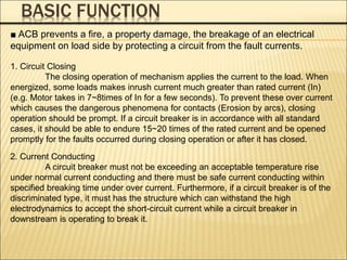
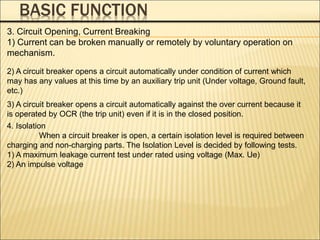
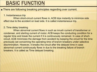
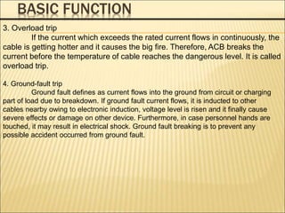
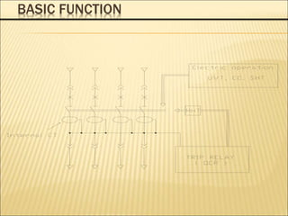
1. An ACB prevents fires, property damage, and equipment breakage by protecting electrical circuits from fault currents.
2. It must safely conduct normal currents, trip automatically for over currents, and provide isolation when open.
3. Key functions include closing circuits, conducting current, opening circuits manually or automatically for faults, and providing isolation when open.


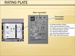
![MAIN NAMEPLATE
TYPE
AH 630AF~6300AF
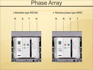
Phase Array
D Standard RST(N) For
630AF~2000AF
W Reverse NRST
For 630AF~2000AF
E Standard RST(N) For
2000AF~4000AF
X Reverse NRST
For 2000AF~4000AF
G Standard RST(N) For
4000AF~6300AF
Z Reverse NRST
For 4000AF~6300AF
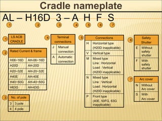
AH – 10 D 3 – 10 A
1 2 3 5 6
4
1 3
Ampere frame
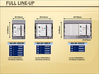
06 630AF
08 800AF
10 1000AF
13 1250AF
~ ~
32 3200AF
40 4000AF
50 5000AF
63 6300AF
2
No. of pole
3 3 pole
4 4 pole
4
Reted current (CT Spect.)
02 200A
~ ~
63 6300A
5
Connections
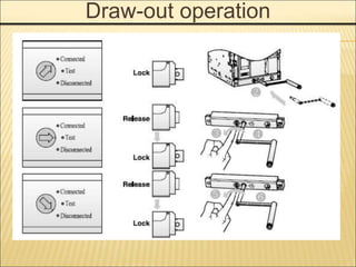
J Manual [Draw-out type]
A Automatic [Draw-out type]
H Horizontal [Fix type]
V Vertical [ Fix type]
M Line : Horizontal, Load :
Vertical [Fix type]
N Line : Vertical, Load :
Horizontal [Fix type]
6](https://image.slidesharecdn.com/susolacbcybertraining-220718075321-6fee2155/85/Susol-ACB-Cyber-Training-ppt-9-320.jpg)
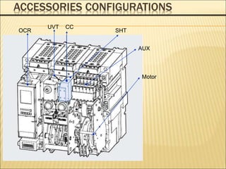
![Accessories Configurations
When a circuit breaker is tripped by OCR which
operates against the faulty current
(Over Current Relay), Trip Alarm switch provides the
information regarding the trip of circuit
breaker by sending the electrical signal from the
mechanical indicator on main cover of main
circuit breaker or internal auxiliary switch. (Installed
at the inside of circuit breaker)
Trip Alarm Contact [AL]](https://image.slidesharecdn.com/susolacbcybertraining-220718075321-6fee2155/85/Susol-ACB-Cyber-Training-ppt-17-320.jpg)
![Accessories Configurations
Manual Reset Button [MRB]
It is a function which resets a circuit
breaker manually when a circuit breaker is tripped by OCR.](https://image.slidesharecdn.com/susolacbcybertraining-220718075321-6fee2155/85/Susol-ACB-Cyber-Training-ppt-18-320.jpg)
![Accessories Configurations
Following tripping, this function resets the "fault trip" alarm contacts(AL) and
the mechanical
indicator(MRB) and enables circuit breaker closing.
Push button swich : AC 125V 10A, AC 250V 6A, DC 110V 2.2A, DC 220V 1.1A
Registive load
Remote Reset Switch [RES]](https://image.slidesharecdn.com/susolacbcybertraining-220718075321-6fee2155/85/Susol-ACB-Cyber-Training-ppt-19-320.jpg)