Design of Beams: Bending Stresses, Moment Capacity, and Lateral Torsional Buckling
•
6 likes•509 views

14-Design of Beam (Steel Structural Design & Prof. Shehab Mourad)

Recommended
Recommended
More Related Content
What's hot
What's hot (20)
Similar to Design of Beams: Bending Stresses, Moment Capacity, and Lateral Torsional Buckling
Similar to Design of Beams: Bending Stresses, Moment Capacity, and Lateral Torsional Buckling (20)
More from Hossam Shafiq II
More from Hossam Shafiq II (20)
Recently uploaded
Recently uploaded (20)
Design of Beams: Bending Stresses, Moment Capacity, and Lateral Torsional Buckling
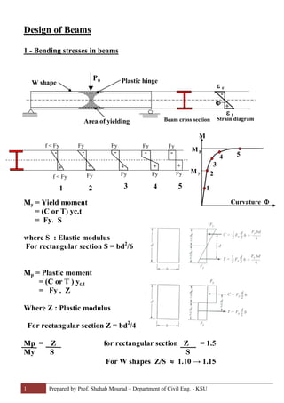
- 1. 1 Prepared by Prof. Shehab Mourad – Department of Civil Eng. - KSU sDesign of Beam Bending stresses in beams-1 My = Yield moment = (C or T) yc.t = Fy. S where S : Elastic modulus For rectangular section S = bd2 /6 Mp = Plastic moment = (C or T ) yc.t = Fy . Z Where Z : Plastic modulus For rectangular section Z = bd2 /4 Mp = Z for rectangular section Z = 1.5 My S S For W shapes Z/S ≈ 1.10 → 1.15 M Curvature Φ 1 2 3 4 5 M p M y Pu Plastic hingeW shape Area of yielding ε t ε c - +Φ Strain diagramBeam cross section f < Fy f < Fy Fy Fy Fy Fy Fy Fy Fy Fy + + + + + - - - - - 1 2 3 4 5
- 2. 2 Prepared by Prof. Shehab Mourad – Department of Civil Eng. - KSU 2- Effect of beam unbraced length on its moment capacity Buckling of the compression flange of the beam can occur if the unbraced length of the compression flange ( Lb) exceeds certain values Lp : Is the largest value of unbraced length that Mp can be reached Lr : is the largest value of unbraced length that cause inelastic torsional buckling
- 3. 3 Prepared by Prof. Shehab Mourad – Department of Civil Eng. - KSU 3 - Beam bending strength Resistance factor for flexural (Φ) = 0.90 (a) if Lb ≤ L p (Zone 1) Φ Mn = least of Φ Mp Φ 1.5 Fy . S (b) if Lp < Lb ≤ Lr (Zone 2) (inelastic lateral torsional buckling) Φ Mn = Φ Cb [ Mp – ( Mp – Mr) (Lb - Lp) ] ≤ Φ Mp (Lr – Lp) = Φ Cb [ Mp – BF (Lb - Lp) ] ≤ Φ Mp Where, Lp, Lr, Mp, Mr, BF are obtained from LRFD tables Cb : is a modification factor for non-uniform moment diagram ( c ) if Lb > Lr (Zone 3) ( Elastic lateral torsional buckling) Φ Mn = Φ Cb Mcr Where Mcr is the critical moment at which the beam will twist elastically due to the elastic buckling of the compression flange, its values are obtained from graphs