10-Design of Tension Member with Bolted Connection (Steel Structural Design & Prof. Shehab Mourad)
•
5 likes•1,313 views

10-Design of Tension Member with Bolted Connection (Steel Structural Design & Prof. Shehab Mourad)

Recommended
Recommended
More Related Content
What's hot
What's hot (20)
Similar to 10-Design of Tension Member with Bolted Connection (Steel Structural Design & Prof. Shehab Mourad)
Similar to 10-Design of Tension Member with Bolted Connection (Steel Structural Design & Prof. Shehab Mourad) (20)
More from Hossam Shafiq II
More from Hossam Shafiq II (20)
Recently uploaded
Recently uploaded (20)
10-Design of Tension Member with Bolted Connection (Steel Structural Design & Prof. Shehab Mourad)
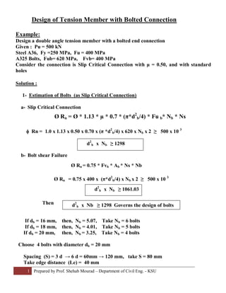
- 1. 1 Prepared by Prof. Shehab Mourad – Department of Civil Eng. - KSU Design of Tension Member with Bolted Connection Example: Design a double angle tension member with a bolted end connection Given : Pu = 500 kN Steel A36, Fy =250 MPa, Fu = 400 MPa A325 Bolts, Fub= 620 MPa, Fvb= 400 MPa Consider the connection is Slip Critical Connection with µ = 0.50, and with standard holes Solution : 1- Estimation of Bolts (as Slip Critical Connection) a- Slip Critical Connection f Rn = 1.0 x 1.13 x 0.50 x 0.70 x (π *d2 b/4) x 620 x Nb x 2 ≥ 500 x 10 3 b- Bolt shear Failure Ø Rn = 0.75 x 400 x (π*d2 b/4) x Nb x 2 ≥ 500 x 10 3 Then If db = 16 mm, then, Nb = 5.07, Take Nb = 6 bolts If db = 18 mm, then, Nb = 4.01, Take Nb = 5 bolts If db = 20 mm, then, Nb = 3.25, Take Nb = 4 bolts Choose 4 bolts with diameter db = 20 mm Spacing (S) = 3 d → 6 d = 60mm → 120 mm, take S = 80 mm Take edge distance (Le) = 40 mm Ø Rn = Ø * 1.13 * µ * 0.7 * (π*d2 b/4) * Fu b* Nb * Ns Ø Rn = 0.75 * Fvb * Ab * Ns * Nb d2 b x Nb ≥ 1298 d2 b x Nb ≥ 1061.03 d2 b x Nb ≥ 1298 Governs the design of bolts
- 2. 2 Prepared by Prof. Shehab Mourad – Department of Civil Eng. - KSU c – Bearing failure Ø Rn = 0.75 x 2.4 x 400 x 20 x tmin x 4 ≥ 500 x 10 3 tmin ≥ 8.68 mm, for one angle tmin ≥ 8.68/2 = 4.34 mm , for guest plate tmin ≥ 8.68 mm Choose angle thickness = 6.40 mm (from LRFD standard section tables) And guest plate thickness = 12 mm 2- Estimation of Angle Sizes a- Yielding of gross area Ø Rn = 0.9 x Ag x Fy = 0.9 x Ag x 250 ≥ 500 x 10 3 b- Fracture of net area Ø Rn = 0.75 x An x U x Fu, assume U = 0.85 for Nb ≥ 3 d h = 20 + 3 = 23 mm = 0.75 x ( Ag – 2 x 23 x 6.40 ) x 0.85 x 400 ≥ 500 x 10 3 Therefore, Ag ≥ 2255 mm2 governs the design of angles Area of one angle ≥ 2255 / 2 = 1128 mm2 From LRFD tables choose angle 102 x 89 x 6.40 mm, Area gross = 1180 mm2 , c.g x = 23.1 mm From Table 3.1, g = 2.5 in = 63.5 mm Recalculate the right value of U y’’ = ( 89 x 6.4 x 3.2) + (57.1 x 6.4 x 34.95) 89 x 6.4 + 57.1 x 6.4 = 15.60 mm y* = 63.5 – 15.60 = 47.90 mm x = larger of 23.1 mm or 47.90 mm Ø Rn = 0.75 * 2.4 * Fu * db * tmin * Nb Ag ≥ 2222.2 mm2 Ag ≥ 2255 mm2 40 80 80 80 6.4 mm 89 mm 63.5 mm 57.1 mm 6.4 mm 23.1 mm y‘’ y* 38.1 mm
- 3. 3 Prepared by Prof. Shehab Mourad – Department of Civil Eng. - KSU Lc = 3 x 80 = 240 mm U = 1- 47.90 / 240 = 0.80 ≤ 0.90 Check fracture at effective area Ø Rn= 0.75 x (1180 x 2 – 2 x 23 x 6.40 )x 0.80 x 400 / 1000 = 495.744 kN < 500 kN Not O.K Use larger spacing, take S = 100 mm = 5d, and Le = 50 mm Lc = 3 x100 = 300 mm, U = 1 – 47.90 / 300 = 0.84 Therefore, Ø Rn = 0.75 x ( 1180 x 2 – 2 x 23 x 6.40 ) x 0.84 x 400 / 1000 = 520 kN > 500 kN O.K 3- Check Block Shear Rupture of Angles Lv = 3S + Le = 300 + 50 = 350 mm, Avg = 350 x 6.4 x 2 = 4480 mm2 Avn = 4480 – 3.50 x 23 x 6.4 x 2 = 3449.6 mm2 Lt = 38.1 mm , Atg = 38.1 x 6.4 x 2 = 487.68 mm2 , At n = 487.68 – 0.5 x 23 x 6.40 = 414 mm2 Fu Atn = 165600 N, and 0.6 Fu Avn = 827904 N Therefore, 0.6 Fu Avn > Fu Atn, then. Ø Rn = 0.75 (827904 + 250 x 487.68 ) / 1000 = 712 kN > 500 kN O.K Note: the strength of Guesst plae should also be checked to be ≥ 500 kN Use double angles 102 x 89 x 6.40 with 4 M20 A325 bolts, with spacing 100 mm and edge distance = 50 mm, gage distance = 63.5 mm
- 4. 4 Prepared by Prof. Shehab Mourad – Department of Civil Eng. - KSU Design of Tension Member with Welded Connection Example: Design a double angle tension member with a welded end connection Given : Pu = 500 kN Steel A36, Fy =250 MPa, Fu = 400 MPa Use Weld, FEX = 500 MPa Solution : 1- Assume that yielding on gross area governs the design Ø Rn = 0.90 Fy Ag = 0.9 x 250 x Ag ≥ 500 x103 Ag ≥ 2222.2 mm2 , therefore each angle gross area ≥ 1111.1 mm2 From LRFD Tables, choose double angles 88.9 x 63.5 x 7.9 mm Ag of one angle = 1148 mm2 2- Estimation of weld Length (Take weld size = 6 mm) Longitudinal welds strength per unit length a) Weld Fracture, Ø Rn = 0.75 x 0.6 x FEx x 0.707 x Sw x 2 = 0.75 x 0.6 x 500 x 0.707 x 6 x 2 = 1909 N/mm b) Shear fracture of angles, Ø Rn = 0.75 x 0.6 x Fu x 2 t angle = 0.75 x 0.6 x 400 x 2 x 7.90 = 2844 N/mm c) Shear rupture of guest plate (take t guesst = 12 mm) Ø Rn = 0.75 x 0.6 x Fu x t guesst = 0.75 x 0.6 x 400 x 12 = 2160 N/mm Pu Pu 1 1 L2 L1 Lg L3 Longitudinal weldsTransversal weld b t h hg tg section (1-1)
- 5. 5 Prepared by Prof. Shehab Mourad – Department of Civil Eng. - KSU Therefore the strength of longitudinal weld = 1909 N/mm Transversal weld strength per unit length a) Weld fracture, Ø Rn = 0.75 x 0.6 x FEx x 0.707 x Sw x 2 x 1.5 = 0.75 x 0.6 x 500 x 0.707 x 6 x 2 x 1.5 = 2863.5 N/mm b) Tensile rupture of guesst plate , Ø Rn = 0.75 x Fu x t guesst = 0.75 x 400 x12 = 3600 N/mm Therefore the strength of transversal weld = 2863.5 N/mm Length of required welds Take L3 = long angle leg = 88.90 mm, and take L1 = L2 Then resistance of welds = 88.9 x 2863.5 + (2 L1 ) 1909 ≥ 500 x 103 Therefore L1 = L2 ≥ 55.2 mm Take L1 = L2 = 60 mm 3- Check Tensile fracture of angles c.g , x of angle = 16.17, Lc = L1 = 60 mm For both transversal and longitudinal welds, U = 1 – (16.17 / 60 ) = 0.73 Ag of two angles = 1148 x 2 = 2296 mm2 Ø Rn = 0.75 x 400 x (0.73 x 2296) = 503 kN > 500 kN O.K 4- Check Block shear of angles Lv = L1 = 60 mm , Av = 60 x 2 x 7.9 = 948 mm2 Lt = 88.9 – 7.90 = 81 mm, At = 81 x 2 x 7.90 = 1279.8 mm2 0.6 Fu Av = 0.6 x 400 x 948 = 227520 N Fu At = 400 x 1279.8 = 511920 N > 0.6 Fu Av Therefore, Ø Rn = 0.75 (511920 + 0.6 x 250 x 948) / 1000 = 490.6 kN < 500 kN Not O.K Therefore choose a larger longitudinal weld length, Take L1= L2 = 70 mm Lv= L1 = 65 mm, Av = 70 x 2 x 7.9 = 1106 mm2 0.6 Fu Av = 0.6 x 400 x 1106 = 265440 < Fu At Therefore, Ø Rn = 0.75 (511920 + 0.6 x 250 x 1106) / 1000 = 508 kN > 500 kN O.K Use double angles 88.9 x 63.5 x 7.9 with longitudinal welds L1= L2 = 70 mm, and L3 = 88.90 mm