Objective of theLecture
•To introduce horizontal alignment
design
The learner should be able to:
•To design horizontal tangents and
curves to satisfy safety and other
criteria
TR 320 Lecture 6: Horizontal Alignment Design 2
3.
Horizontal Tangent asa design element
•Design elements of the horizontal alignment
are:
•The tangent
•The circular curve including super-
elevation design, and
•The transition curve
3
TR 320 Lecture 6: Horizontal Alignment Design
4.
•To enhance safetythe tangent
should be designed to:
•Achieve passing sight distance
on two lane roadways
•Minimize excessive speeding
•Minimize danger of glare
•Minimize driver fatigue
TR 320 Lecture 6: Horizontal Alignment Design 4
5.
•This is achievedby:
•Avoid long tangents with constant
grade
•Allow enough distance between
successive curves
•Limit tangents lengths to discourage
speeds beyond design speed
TR 320 Lecture 6: Horizontal Alignment Design 5
6.
The Circular Curve
•Purpose is to achieve “smooth” transition from one tangent to the
next when direction changes
• May be introduced to limit tangent length so as to achieve
safe/pleasant design
• A transition curve may be introduced at the beginning and end of the
circular curve for comfort when entering a circular curve at speeds
above 80 km/hr
TR 320 Lecture 6: Horizontal Alignment Design 6
7.
Design Recommendations
• Germanand SA guidelines discourage tangent lengths longer than 20
times the design speed.
• Consistent design is defined in terms of changes in operating speed
and driver mental effort. Changes > 20 km/hr indicate inconsistent
design. The designer should aim at not more than 10 km/hr.
7
TR 320 Lecture 6: Horizontal Alignment Design
8.
The Circular CurveGeometry -Repetition:
• BC: Beginning of curve – PC: Point of Curvature
• EC: End of Curve – PT: Point of Tangency
• PI: Point of intersection
• Deflection angle (change in direction)
• R: Radius of Curve
• L: Length of Curve – compute from R and deflection angle
• Tangent length - Compute from R and deflection angle
TR 320 Lecture 6: Horizontal Alignment Design 8
9.
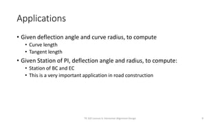
Applications
• Given deflectionangle and curve radius, to compute
• Curve length
• Tangent length
• Given Station of PI, deflection angle and radius, to compute:
• Station of BC and EC
• This is a very important application in road construction
TR 320 Lecture 6: Horizontal Alignment Design 9
10.
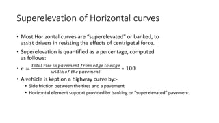
Superelevation of Horizontalcurves
• Most Horizontal curves are “superelevated” or banked, to
assist drivers in resisting the effects of centripetal force.
• Superelevation is quantified as a percentage, computed
as follows:
• 𝑒 =
𝑡𝑜𝑡𝑎𝑙 𝑟𝑖𝑠𝑒 𝑖𝑛 𝑝𝑎𝑣𝑒𝑚𝑒𝑛𝑡 𝑓𝑟𝑜𝑚 𝑒𝑑𝑔𝑒 𝑡𝑜 𝑒𝑑𝑔𝑒
𝑤𝑖𝑑𝑡ℎ 𝑜𝑓 𝑡ℎ𝑒 𝑝𝑎𝑣𝑒𝑚𝑒𝑛𝑡
∗ 100
• A vehicle is kept on a highway curve by:-
• Side friction between the tires and a pavement
• Horizontal element support provided by banking or “superelevated” pavement.
11.
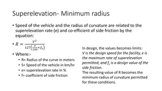
Superelevation- Minimum radius
•Speed of the vehicle and the radius of curvature are related to the
superelevation rate (e) and co-efficient of side friction by the
equation:
• 𝑅 =
𝑉2
127
𝑒
100
+𝑓𝑠
• Where:-
• R= Radius of the curve in meters
• S= Speed of the vehicle in km/hr
• e= superelevation rate in %
• f= coefficient of side friction
In design, the values becomes limits:
V is the design speed for the facility, e is
the maximum rate of superelevation
permitted; and fs is a design value of the
side friction.
The resulting value of R becomes the
minimum radius of curvature permitted
for these conditions.
12.
Task
• Derive therelationship between the curve radius and the two
parameters ( side friction, together with superelevation rate)
13.
Maximum superelevation rates
•AASHTO recommends the use of values between 4% and 12% as
maximum superelevation rates.
• For design purposes only increments of 2% are used.
• The maximum rates varies depending on several factors like terrain,
development density, and frequency of slow moving vehicle
14.
Some considerations forSuperelevation rates
• 12% is the maximum rate in use. At such values, the drivers feels
uncomfortable and driver’s effort to maintain lateral position is high
at lower speeds
• With presence of ice and snow a maximum of 8% is used
• In urban areas the value is set to 4% to 6% since speeds are reduced
due to congestion
• On low speed streets or at intersections, superelevation may be
eliminated.
• Note: Even for the tangent sections, the road can be superelevated or
cambered to provide for cross-drainage
15.
Side friction factors
•Design values of side friction varies with design speed.
• They represent wet pavements and tires in reasonable but not top
condition.
• It also represent frictions that can be safely achieved
16.
Design Values
• Thedesign value of superelevation rate is chosen considering the
factors already mentioned.
• Side friction is chosen depending on design speed as indicated.
• Then the minimum radius of curve is determined from the equation:
• 𝑅 =
𝑉2
127
𝑒
100
+𝑓𝑠
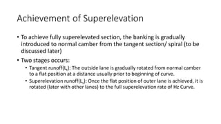
Achievement of Superelevation
•To achieve fully superelevated section, the banking is gradually
introduced to normal camber from the tangent section/ spiral (to be
discussed later)
• Two stages occurs:
• Tangent runoff(Lt): The outside lane is gradually rotated from normal camber
to a flat position at a distance usually prior to beginning of curve.
• Superelevation runoff(Ls): Once the flat position of outer lane is achieved, it is
rotated (later with other lanes) to the full superelevation rate of Hz Curve.
19.
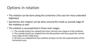
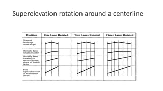
Options in rotation
•The rotation can be done along the centerline ( the case for most undivided
highways)
• Sometimes the rotation can be done around the inside or outside edge of
the roadway as well
• The rotation is accomplished in three main stages:
• 1. The outside lane(s) are rotated from their normal cross-slope to a flat condition.
2. The outside lane(s) are rotated from the flat position until they equal the normal
cross-slope of the inside lanes.
3. All lanes are rotated from the condition of step 2 to the full superelevation of the
horizontal curve.
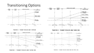
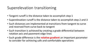
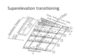
Superelevation transitioning
• Tangentrunoff is the distance taken to accomplish step 1
• Superelevation runoff is the distance taken to accomplish step 2 and 3
• Such distances are implemented at transitions from tangent to curve
and reversed from curve back to tangent
• Such transition is achieved by creating a grade differential between
rotation axis and pavement edge lines
• Such grade difference is the relative gradient an important parameter
to consider for achieving safe and comfortable operations
23.
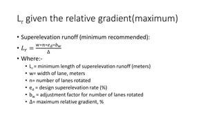
Lr given therelative gradient(maximum)
• Superelevation runoff (minimum recommended):
• 𝐿𝑟 =
𝑤∗𝑛∗𝑒𝑑∗𝑏𝑤
Δ
• Where:-
• Lr = minimum length of superelevation runoff (meters)
• w= width of lane, meters
• n= number of lanes rotated
• ed = design superelevation rate (%)
• bw = adjustment factor for number of lanes rotated
• Δ= maximum relative gradient, %
24.
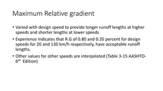
Maximum Relative gradient
•Varied with design speed to provide longer runoff lengths at higher
speeds and shorter lengths at lower speeds
• Experience indicates that R.G of 0.80 and 0.35 percent for design
speeds for 20 and 130 km/h respectively, have acceptable runoff
lengths.
• Other values for other speeds are interpolated (Table 3-15 AASHTO-
6th Edition)
25.
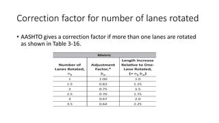
Correction factor fornumber of lanes rotated
• AASHTO gives a correction factor if more than one lanes are rotated
as shown in Table 3-16.
26.
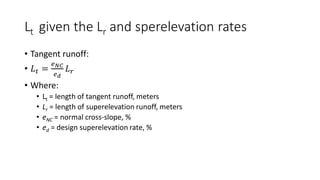
Lt given theLr and sperelevation rates
• Tangent runoff:
• 𝐿𝑡 =
𝑒𝑁𝐶
𝑒𝑑
𝐿𝑟
• Where:
• Lt = length of tangent runoff, meters
• Lr = length of superelevation runoff, meters
• eNC = normal cross-slope, %
• ed = design superelevation rate, %
Transitioning continued
• Forcomfortable operations, 60% to 90% of total runoff is achieved on
tangent, while remaining runoff is achieved on horizontal curve
• Mostly it is considered that two thirds (2/3) of the transition occur on
tangent while one third (1/3) occur on curves.
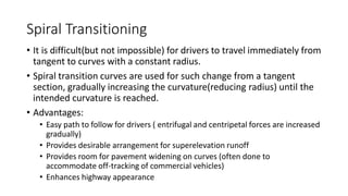
Spiral Transitioning
• Itis difficult(but not impossible) for drivers to travel immediately from
tangent to curves with a constant radius.
• Spiral transition curves are used for such change from a tangent
section, gradually increasing the curvature(reducing radius) until the
intended curvature is reached.
• Advantages:
• Easy path to follow for drivers ( entrifugal and centripetal forces are increased
gradually)
• Provides desirable arrangement for superelevation runoff
• Provides room for pavement widening on curves (often done to
accommodate off-tracking of commercial vehicles)
• Enhances highway appearance
31.
Spiral transitioning
• Spiralcurves are not always used as condtruction is difficult and is
associated with higher costs than simple circular curves
• Recommended for higher volume situations ans when degree of
curvature exceeds 3 degrees
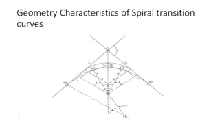
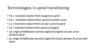
Terminologies in spiraltransitioning
• T.S.= transition station from tangent to spiral
• S.C.= transition station from spiral to circular curve
• c.s.= transition station from circular curve to spiral
• S.T.= transition station from spiral to tangent
• .Δ= angle of deflection (central angle) of original circular curve
without spiral
• Δs= angle of deflection (central angle) of circular portion of curve with
spiral
35.
Terminologies Contd’
• δ=angle of deflection for spiral portion of curve
• Ls= length of the spiral, ft
36.
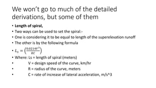
We won’t goto much of the detailed
derivations, but some of them
• Length of spiral,
• Two ways can be used to set the spiral:-
• One is considering it to be equal to length of the superelevation runoff
• The other is by the following formula
• 𝐿𝑠 =
0.0214𝑉3
𝑅𝐶
• Where: Ls = length of spiral (meters)
• V = design speed of the curve, km/hr
• R = radius of the curve, meters
• C = rate of increase of lateral acceleration, m/s^3
37.
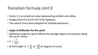
Transition formula cont’d
•Factor C is an empirical value representing comfort and safety.
• Ranges from 0.3 to 0.9 m/s^3 for highways.
• The value 0.3 has been adopted for railroad operations.
• Angle of deflection for the spiral:
• Deflection angle for spiral reflects the average degree of curvature along
the spiral: Hence
• 𝛿 =
𝑙2
2𝑅𝐿𝑠
• At full length: 𝛿 =
𝐿𝑠
2𝑅
or
𝐿𝑠𝐷
200
(in degree of curve)
38.
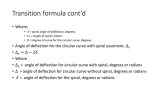
Transition formula cont’d
•Where:
• 𝛿 = spiral angle of deflection, degrees
• Ls = length of spiral, meters
• D = degree of curve for the circular curve, degrees
• Angle of deflection for the circular curve with spiral easement, Δs
• Δs = Δ − 2𝛿
• Where
• Δs = angle of deflection for circular curve with spiral, degrees or radians
• Δ = angle of deflection for circular curve without spiral, degrees or radians
• 𝛿 = angle of deflection for the spiral, degrees or radians
39.
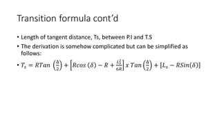
Transition formula cont’d
•Length of tangent distance, Ts, between P.I and T.S
• The derivation is somehow complicated but can be simplified as
follows:
• 𝑇𝑠 = 𝑅𝑇𝑎𝑛
Δ
2
+ 𝑅𝑐𝑜𝑠 𝛿 − 𝑅 +
𝐿𝑠
2
6𝑅
𝑥 𝑇𝑎𝑛
Δ
2
+ 𝐿𝑠 − 𝑅𝑆𝑖𝑛 𝛿
40.
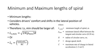
Minimum and Maximumlengths of spiral
• Minimum lengths:
• Considers drivers’ comfort and shifts in the lateral position of
vehicles.
• Therefore: Ls, min should be larger of:
• 𝐿𝑠,𝑚𝑖𝑛 = 24 𝑝𝑚𝑖𝑛 𝑅
• Or
• 𝐿𝑠 =
0.0214𝑉3
𝑅𝐶
41.
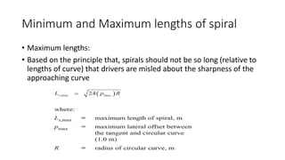
Minimum and Maximumlengths of spiral
• Maximum lengths:
• Based on the principle that, spirals should not be so long (relative to
lengths of curve) that drivers are misled about the sharpness of the
approaching curve
42.
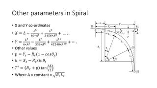
Other parameters inSpiral
• X and Y co-ordinates
• 𝑋 = 𝐿 −
𝐿5
40∗𝐴4 +
𝐿9
3456∗𝐴8 + … . .
• 𝑌 =
𝐿3
6∗𝐴2 −
𝐿7
336∗𝐴6 +
𝐿11
42240∗𝐴10 + ⋯ .
• Other values
• 𝑝 = 𝑌𝑠 − 𝑅𝑐 1 − 𝑐𝑜𝑠𝜃𝑠
• 𝑘 = 𝑋𝑠 − 𝑅𝑐𝑠𝑖𝑛𝜃𝑠
• 𝑇′
= 𝑅𝑐 + 𝑝 tan
Δ
2
• Where A = constant = 𝑅𝑐𝐿𝑠
43.
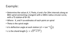
Example:
• Determine thevalues X, Y, Theta, d and c for 20m intervals along an
80m spiral connecting a tangent with a 500m radius circular curve,
with a TS station of 8+ 05.
• Where: X, and Y co-ordinates of each point on spiral
• Theta is the spiral angle
• d is deflection angle at each station (𝑑 = tan−1
(
𝑌
𝑋
))
• c is the chord length 𝑐 = 𝑋2 + 𝑌2
44.
Example 2 Designfor superelevation
• A two-lane highway (3.6 m lanes) with a design speed of 100 km/h
has a 400 m radius horizontal curve connecting tangents with
bearings of N75E° and S78E°. Determine the superelevation rate, the
length of spiral if the difference in grade between the centerline and
edge of traveled way is limited to 1/200, and the stations of the TS,
SC, CS, and ST, given that the temporary station of the P.I. is 150 + 00.
The length of the spiral should be rounded up to the next highest 20
m interval.