The document discusses key considerations for designing horizontal curves, including:
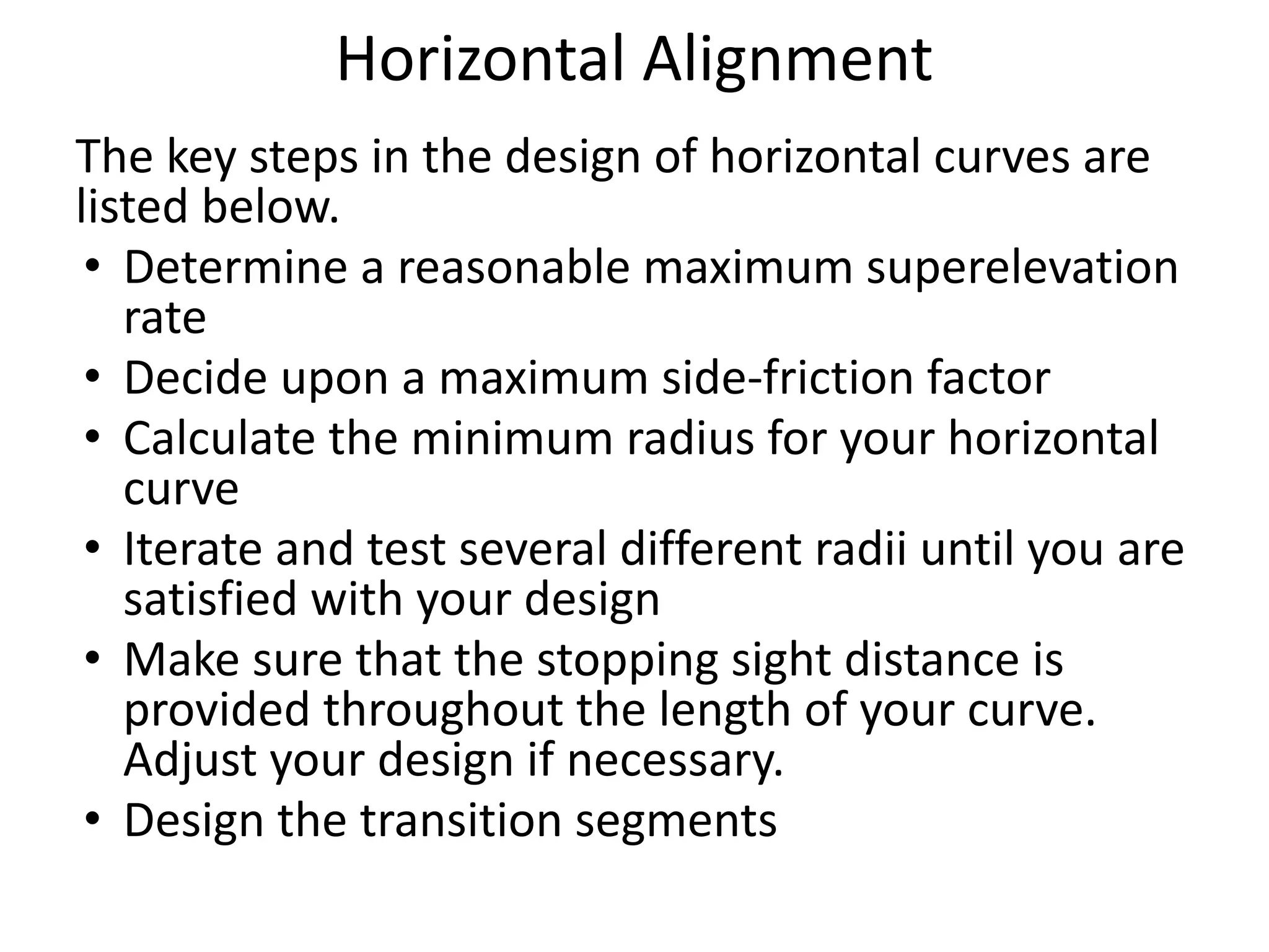
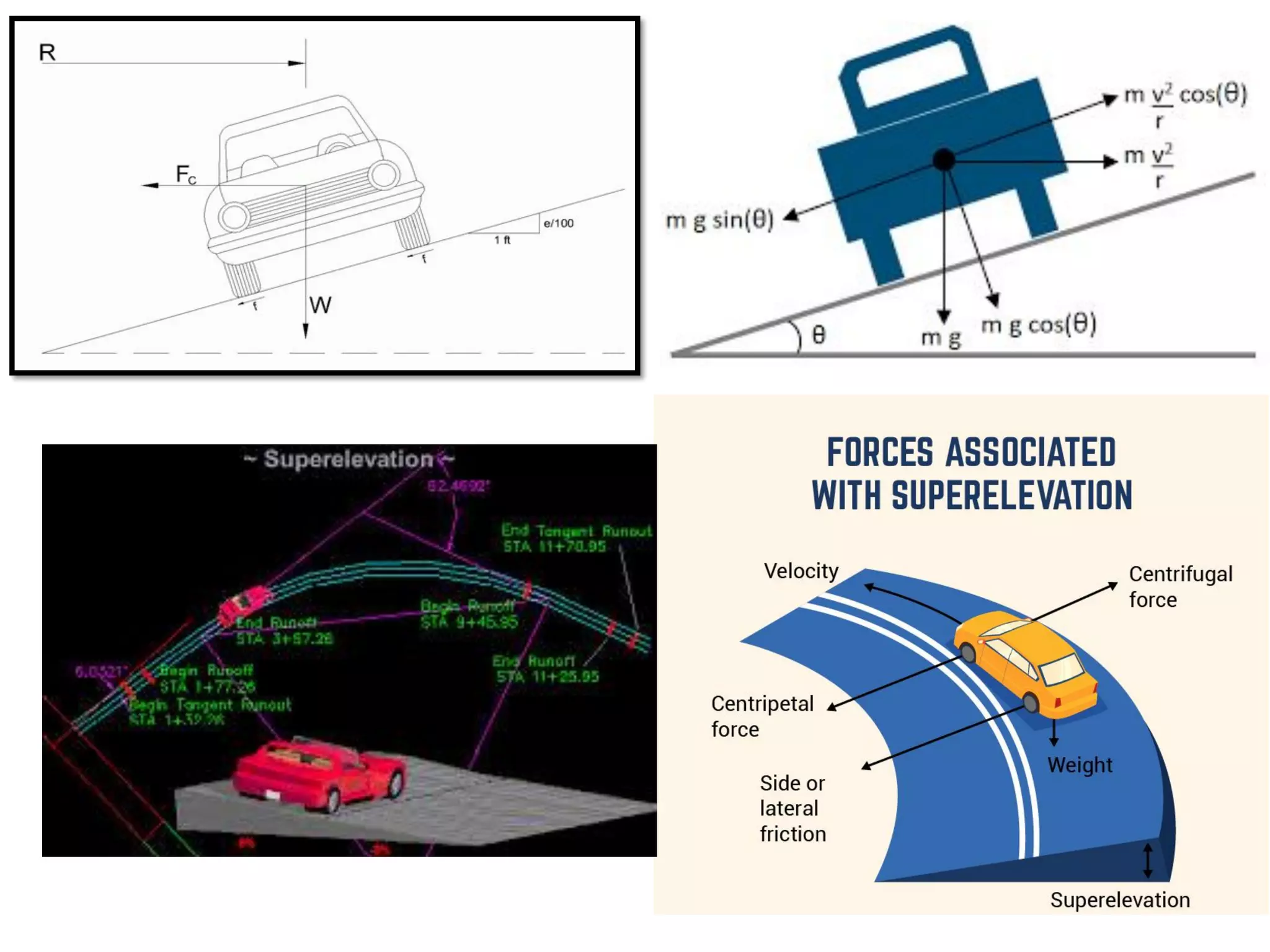
1. Calculating the minimum radius based on design speed, superelevation rate, and side friction factor.
2. Establishing practical maximum limits for superelevation rate of 8-12% due to factors like snow, driver comfort.
3. Using transition curves to gradually develop superelevation over a length determined by design speed and superelevation rate.
4. Widening the carriageway on curves below a certain radius to allow vehicles to pass safely. Iterative design is recommended to consider factors like cost, sight distance, and aesthetics beyond minimum standards.