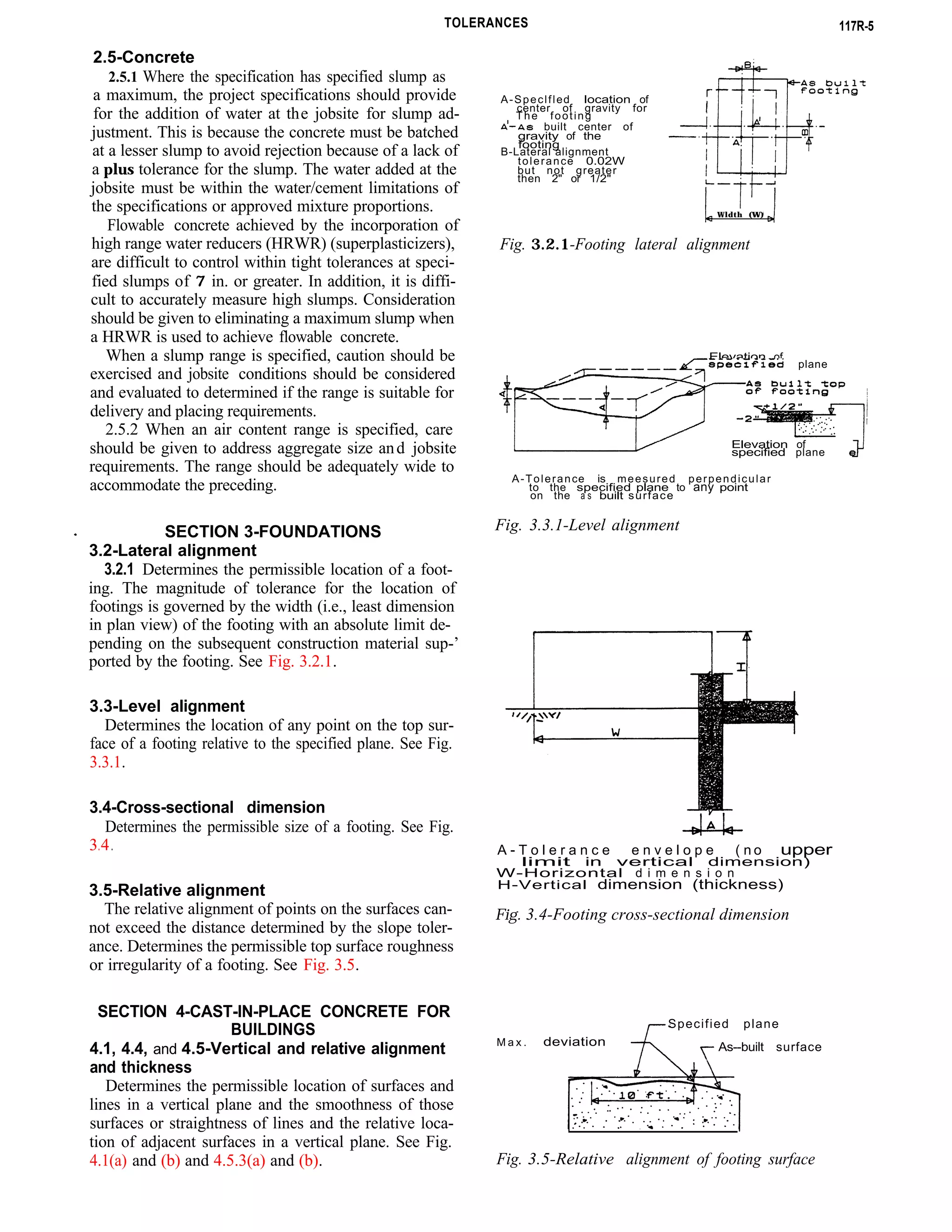
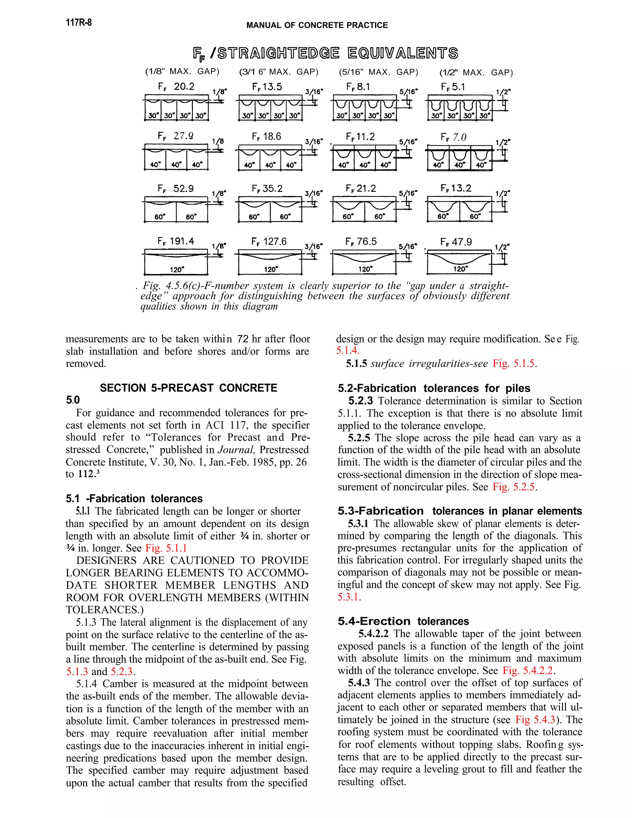
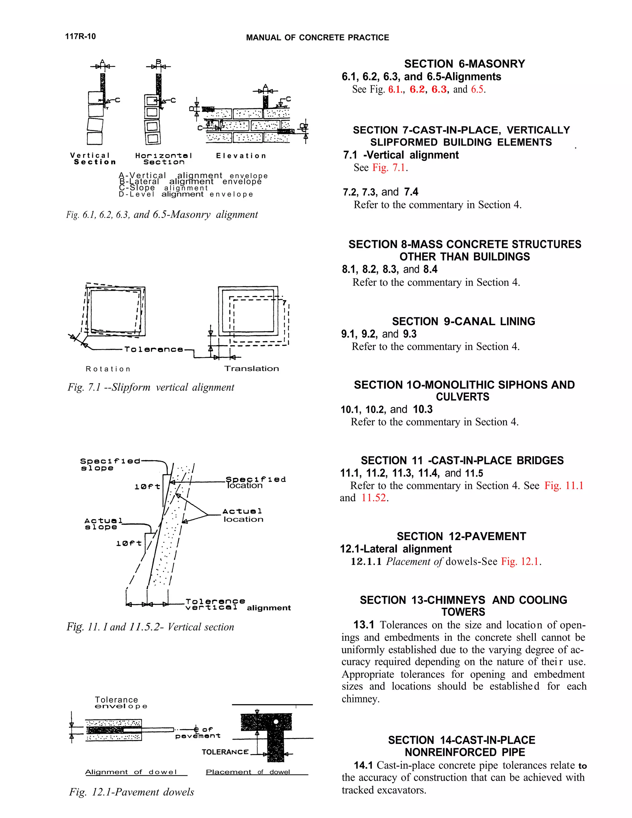
SlideShare a Scribd company logo
ACI 117R-90
Commentary on Standard Specifications for Tolerances for
Construction and Materials
Reported by ACI Committee 117
W. Robert Little Russell S. Fling
Chairman Chairman, Editorial Subcommittee
S. Allen Face
Thomas C. Heist
Richard A. Kaden
Ross Martin
Peter Meza
Andrawos Morcos
Clark B. Morgan Jr.
Harry M. Palmbaum
William S. Phelan
B. J. (Duke) Pointer
Dean E. Stephan Jr.*
Eldon Tipping
Carl S. Togni
Joe V. Williams, Jr.
This report is a commentary on the Standard Specifications for ToI-
erances for Concrete Construction and Materials. It iis intended to be
used with ACI 117 for clarity of interpretation and insight in to the
intent of the committee regarding the application of the tolerances set
forth therein.
Keywords: bending (reinforcing steels); building codes; concrete construction;
concrete piles; concretes; floors; formwork (construction); masonry; mass con-
crete; piers; precast concrete; prestressed concrete; reinforcing steels , specifi-
cations; splicing; standards; tolerances (mechanics).
INTRODUCTION
This commentary pertains to “Standard Specifications
for Tolerances for Concrete Construction and Mate-
rials (ACI-117).” The purpose of the report is to pro-
vide graphic and written interpretations for the specifi-
cation and its application.
No structure is exactly level, plumb, straight, and
true. Fortunately, such perfection is not necessary.
Tolerances are a means to establish permissible varia-
tion in dimension and location, giving both the de-
signer and the contractor parameters within which the
work is to be performed. They are the means by which
the designer conveys to the contractor the performance
expectations upon which the design is based or the use
of the project requires. Such specified tolerances should
reflect design assumptions and project needs, being
neither overly restrictive nor lenient. Necessity rather
than desirability should be the basis of selecting toler-
ances .
ACI Committee Reports, Guides, Standard Practices, and
Commentaries are intended for guidance in designing, plan-
ning, executing, or inspecting construction and in preparing
specifications. Reference to these documents shall not be made
in the Project Documents. If items found in these documents
are desired to be part of the Project Documents they should
be phrased in mandatory language and incorporated in the
Project Documents.
As the title “Standard Specifications for Tolerances
for Concrete Construction and Materials (ACI 117)”
implies, the tolerances given are standard or usual tol-
rances that apply to varidus types and uses of concrete
construction. They are based upon normal needs and
common construction techniques and practices. Spe-
cific tolerances at variance with the standard values can
cause both increases and decreases in the cost of con-
struction.
The required degree of accuracy of performance de-
pends on the interrelationship of several factors:
Structural strength and function requirements
The structure must be safe and strong, reflecting the
design assumptions, and accurate enough in size and
shape to do the job for which it was designed and con-
structed.
Esthetics
The structure must satisfy the appearance needs or
wishes of the owner and the designer.
Economic feasibility
The specified degree of accuracy has a direct impact
on the cost of production and the construction method.
In general, the higher degree of accuracy required, the
higher the cost of obtaining it.
Relationship of all components
The required degree of accuracy of individual parts
can be influenced by adjacent units and materials, joint
and connection details, and the possibility of the accu-
mulation of tolerances in critical dimensions.
*Chairman during initial development of this document.
copyright 1990, American Concrete Institute.
All rights reserved including rights of reproduction and use in any form or
by any means, including the making of copies by any photo process, or by any
electronic or manual device, printed, written, or oral, or recordin g for sound
or visual reproduction or for use in any knowledge or retrieval system or de-
vice, unless permission in writing is obtained from the copyright proprietors.
117R-1
117R-2 MANUAL OF CONCRETE PRACTICE
Construction techniques
The feasibility of a tolerance depends on available
craftsmanship, technology, and materials.
Properties of materials
The specified degree of accuracy for shrinkage and
prestressed camber should recognize the degree of dif-
ficulty of predetermining deflection due to shrinkage
and prestressed camber.
Compatibility
Designers are cautioned to use finish and architec-
tural details that are compatible with the type and an-
ticipated method of construction. Finish and architec-
tural details used should be compatible with the con-
crete tolerances which are achievable.
Job conditions
Unique job situations and conditions must be con-
sidered. The designer must specify and clearly identify
those items that require either closer or more lenient
tolerances as the needs of the project dictate.
Measurement
Mutually agreed-upon control points and bench
marks must be provided as reference points for mea-
surements to establish the degree of accuracy of items
produced and for verifying the tolerances of the items
produced. Control points and bench marks should be
established and maintained in an undisturbed condition
until final completion and acceptance of the project.
Project document references
ACI Specification documents-The following Amer-
ican Concrete Institute documents provide mandatory
requirements for concrete construction and may be ref-
erenced in the Project Documents:
ACI 117
ACI 301
ACI 531.1
Standard Specifications for Toler-
ances for Concrete Construction and
Materials
Specifications for Structural Con-
crete for Buildings
Specification for Concrete Masonry
Construction
ACI informative documents-ACI Committee Re-
ports, Guides, Standard Practices, and Commentaries
are intended for guidance in designing, planning, exe-
cuting, or inspecting construction, and in preparing
plans and specifications. Reference to these Reports,
Guides, and Standard Practices should not be included
in the Project Documents. If the Architect/Engineer
desires to include items found in these ACI documents
in the Project Documents, they should be rephrased in
mandatory language and incorporated into the Project
Documents.
The documents of the following American Concrete
Institute Committees cover practice, procedures, and
state-of-the-art guidance for the categories of construc-
tion as listed.
General building
Special structures
Precast construction
Masonry construction
Materials
ACI 302, 303, 304, 318, 347
ACI 307, 313, 316, 325, 332,
334, 344, 345, 349, 350, 357,
358
ACI 347
ACI 531
ACI 211, 223, 302, 304, 315,
318, 531, 543
TABLE OF CONTENTS
Introduction, p. 117-R-1
Section 1 -General requirements, p. 117R-2
Section 2--Materials, p. 117R4
Section 3-Foundations, p. 117R-5
Section 4-Cast-in-place concrete for buildings,
p. 117R-5
Section 5-Precast concrete, p. 117R-8
Section 6-Masonry, p. 117R-10
Section 7-Cast-in-place, vertically slipformed
structures,’ p. 117R-10
Section 8-Mass concrete structures other than
buildings, p. 1 17R-10
Section 9-Canal lining, p. 117R-10
Section 10-Monolithic siphons and culverts, p.
117R-10
Section 11 -Cast-in-place bridges, p. 117R-10
Section 12-Pavement, p. 117R-10
Section 13-Chimneys and cooling towers, p.
117R-11
Section 14-Cast-in-place nonreinforced pipe, p.
117R-11
Section 15- References, p. 117R-11
SECTION l-GENERAL REQUIREMENTS
1.3-Definitions
Bowing-See Fig. 1.3.1.
Flatness-See Fig. 1.3.2.
Lateral alignment-See Fig. I .3.3.
Level alignment-See Fig. 1.3.4.
Relative alignment-See Fig. 1.3.5.
Vertical alignment-See Fig. 1.3.6.
Warping-See Fig. 1.3.7.
Level alignment, lateral alignment, and vertica l
alignment are used to establish a tolerance envelope
within which permissible variations can occur. Relative
alignment, in addition to designating allowable relative
displacements of elements, is used to determine the rate
of change of adjacent points (slope tolerance) occur-
ring within the tolerance envelope. In this fashion the
slope and smoothness of surfaces and lines within a
tolerance envelope are controlled. Abrupt changes,
. alignment of
Line A A O r plane A is: d at
C R O S S S E C T I O N C R O S S S E C T I O N
any point along line AA or
C O N V E X B O W I N G C O N C A V E B O W I N G
any point within plane A
taken perpendicular to the
specified horizontal plane.
Specified
Horizontal Plane
Exposed face
( Convex )
Fig. 1.3.4-Level alignment
bowing
cast C o n
Pane 1
E L E V A T I O N
A B
d
d C
d
D
Fig. 1.3.1-Bowing A B C
P l a n e
View A
P l a n e A
the exposed surface
Vertical alignment of
line AA or plane A
Specified plane
is d at any point along
line AA or any point
within plane A taken
perpendicular to the
specified vertical
plane or line.
" d " I s the
alignment in the
same plane
Relative
"d" Is -therelative
3
alignment between
d d nearby adjacent
e l e m e n t s .
c
Fig. 1.3.5-Relative alignment
View A (edge view)
Fig. 1.3.2-Flatness
Fig. 1.3.6- Vertical alignment
Specified line
to the specified line.
Fig. 1.3.3-Lateral alignment Fig. 1.3.7-Warping
11 7R-4 MANUAL OF CONCRETE PRACTICE
s u r f a c e s are
distance and
(2.2.3)
F o r m e d s u r f a c e
( S O F F I T )
C o v e r
(2.2.3)
. .
M e m b e r s f o r m e d o n o n e side o n l y
Fig. 2.2.2(a)-Reinforcement placement
A-Absolute LIMIT determined by cover
r e d u c t i o n can govern t h e location of
o n e s l d e o f t h e t o l e r a n c e e n v e l o p e
B-Clear distance tolerance e n v e l o p e
C-Tolerance e n v e l o p e
Fig. 2.2.2(b) and 2.2.3(b)-Reinforcement placement
F o r m : ,
Clear distance
(2.2.2)
r
2 . .
M e m b e r f o r m e d o n t w o s i d e s
Fig. 2.2.3(a)-Reinforcement placement
A - A b s o l u t e limit o n tolerance e n v e l o p e
d u e t o r e d u c t i o n in distance b e t w e e n
reinforcing
B - S p e c l f l e d spacing
C-Tolerance e n v e l o p e
Fig. 2.2.4 and 2.2..5-Reinforcement placement
t e : M l n l m u m c o v e r
u s t b e maintained
C - T o l e r a n c e envelope o t h e r
locations (+-2" w i d e )
D-Tolerance e n v e l o p e a t
d l s c o n t l n o u s e n d s
( +-1" wide )
Fig. 2.2.7-Reinforcement placement,
cation
longitudinal lo-
A - M i n l m u m l a p l e n g t h o r e m b e d m e n t ( n o
m a x i m u m side o f t o l e r a n c e e n v e l o p e )
Fig. 2.2.8-Reinforcement placement, embedment and laps
n c e
SECTION 2-MATERIALS
2.2-Reinforcement
In the absence of specific design details shown or
specified on the contract documents, CRSI MSP-1, Appen-
dix D, should be followed by estimators, detailers, and
placers.
2.2.2 and 2.2.3 The tolerance for placing reinforcing
steel is predicated upon measurements of the formed
surfaces for quality control during construction and
from the resulting surfaces for forensic analysis. It
consists of an envelope with an absolute limitation on
one side of the envelope determined by the limit on the
reduction in cover. See Fig. 2.2.2(a), 2.2.2(b), 2.2.3(a),
and 2.2.3(b).
2.2.4 and 2.2.5 The spacing tolerance of reinforc-
ing consists of an envelope with an absolute limitation
on one side of the envelope determined by the limit on
the reduction in distance between reinforcement. In ad-
dition, the allowable tolerance on spacing shall not
cause a reduction in the specified number of reinforc-
ing bars utilized. See Fig. 2.2.4 and 2.2.5.
offsets, sawtoothing, sloping, etc., of lines and sur-
faces properly located within a tolerance envelope may
be objectionable when exposed to view. The acceptable
relative alignment of points on a surface or line is de-
termined by using a slope tolerance.
2.2.6 The vertical deviation tolerance should be con-
sidered in establishing minimum prestressing tendon
covers, particularly in applications exposed to deicer
chemicals or salt water environments where use of ad-
ditional cover is recommended to compensate for plac-
ing tolerances. Slab behavior is relatively insensitive to
horizontal location of tendons.
2.2.7 and 2.2.8 The tolerance for the location of the
ends of reinforcing steel is determined by these two
sections. See Fig. 2.2.7 and 2.2.8.
TOLERANCES 117R-5
2.5-Concrete
2.5.1 Where the specification has specified slump as
a maximum, the project specifications should provide
for the addition of water at the jobsite for slump ad-
justment. This is because the concrete must be batched
at a lesser slump to avoid rejection because of a lack of
a plus tolerance for the slump. The water added at the
jobsite must be within the water/cement limitations of
the specifications or approved mixture proportions.
Flowable concrete achieved by the incorporation of
high range water reducers (HRWR) (superplasticizers),
are difficult to control within tight tolerances at speci-
fied slumps of 7 in. or greater. In addition, it is diffi-
cult to accurately measure high slumps. Consideration
should be given to eliminating a maximum slump when
a HRWR is used to achieve flowable concrete.
When a slump range is specified, caution should be
exercised and jobsite conditions should be considered
and evaluated to determined if the range is suitable for
delivery and placing requirements.
2.5.2 When an air content range is specified, care
should be given to address aggregate size and jobsite
requirements. The range should be adequately wide to
accommodate the preceding.
SECTION 3-FOUNDATIONS
3.2-Lateral alignment
3.2.1 Determines the permissible location of a foot-
ing. The magnitude of tolerance for the location of
footings is governed by the width (i.e., least dimension
in plan view) of the footing with an absolute limit de-
pending on the subsequent construction material sup-’
ported by the footing. See Fig. 3.2.1.
3.3-Level alignment
Determines the location of any point on the top sur-
face of a footing relative to the specified plane. See Fig.
3.3.1.
3.4-Cross-sectional dimension
Determines the permissible size of a footing. See Fig.
3 4. .
3.5-Relative alignment
The relative alignment of points on the surfaces can-
not exceed the distance determined by the slope toler-
ance. Determines the permissible top surface roughness
or irregularity of a footing. See Fig. 3.5.
SECTION 4-CAST-IN-PLACE CONCRETE FOR
BUILDINGS
4.1, 4.4, and 4.5-Vertical and relative alignment
and thickness
Determines the permissible location of surfaces and
lines in a vertical plane and the smoothness of those
surfaces or straightness of lines and the relative loca-
tion of adjacent surfaces in a vertical plane. See Fig.
4.1(a) and (b) and 4.5.3(a) and (b).
A-Speclfled location of
center of gravity for
The footing
built center of
gravity of the
footing
B-Lateral alignment
tolerance 0.02W
but not greater
then 2" or 1/2"
Wldth (W)
Fig. 3.2.1-Footing lateral alignment
Elevation of
plane
Elevation of
specified plane
A-Tolerance is meesured perpendicular
to the specified plane to any point
on the a s built surface
Fig. 3.3.1-Level alignment
A - T o l e r a n c e e n v e l o p e ( n o upper
limit in vertical dimension)
W-Horizontal d i m e n s i o n
H-Vertical dimension (thickness)
Fig. 3.4-Footing cross-sectional dimension
M a x .
Specified plane
deviation As--built surface
Fig. 3.5-Relative alignment of footing surface
117R-6 MANUAL OF CONCRETE PRACTICE
e n v e l o p e . section 4 . 1
Specified vertical line or p l a n e
Vertical line o r s u r f a c e , a s b u i l t
deviation
d e v i a t i o n
S l o p e tolerance, s e c t i o n 4 . 5 . 3
Tangent -to surface or line
Fig. 4.1(a) and 4.5.3(a)
r Floor s l a b s
Specified location Of e d g e O f slabs
e n v e l o p e , s e c t i o n 4 . 1
S l o p e tolerance. section 4 . 5 . 3
S l o p e f r o m f l o o r t o f l o o r
at edge of slab
Location is o u t o f t o l e r a n c e
Fig. 4.1 (b) and 4.5.3(b)
Fig. 4.1(a), (b) and 4.5.3(a), (b)- Vertical and relative
alignmen t
4.3,4.4, and 4.5-Level a nd vertical alignment
and cross-sectional dimensions
If the level and cross-sectional dimension tolerances
are given, then a suspended (elevated) slab is fully tol-
eranced.
Example:` 12 in. slab-The envelope for the slab ele-
ment extends in. above the specified surface eleva-
tion to in. below the specified soffit elevation. Thus
the slab surface and/or soffit can be in. higher or
lower than specified. The slab thickness can be in.
greater or in. less than specified; the rate of change
in slope of the top surface is toleranced by the and
the soffit is toleranced by the relative alignment and
formed surface tolerances. See Fig. 4.3, 4.4, and
4.5.3(c).
The acceptable elevation envelope of the slab surface
and soffit is in. The rate of change of the adja-
cent surface elevation points within the acceptable ele-
vation is governed by specification Section 4.5.5.
4.5.5 Floor profile finish quality has traditionally
been measured by limiting the gap to be measured un-
der either a freestanding or leveled 10-ft straightedge,
according to the specifier’s requirements. The technol-
ogy for measuring floor profiles has rapidly evolved in
response to the needs of random vehicular traffic in-
dustrial users. This technology provides a welcome al-
ternative and a solution to the generally recognized in-
adequacies of the 1O-ft straightedge to describe and de-
s u r f a c e - - - /
A - L e v e l a l i g n m e n t t o l e r a n c e e n v e l o p e
B- Cross Section dimension t o l e r a n c e
tolerance
C - S l o p e t o l e r a n c e
M a x .
M l n . t o
(Note that max. end m i n .
t o l e r a n c e envelo e m a y
n o t be used simu ltaneouslyy
in this e x a m p l e w i t h o u t
exceeding t h e f o r m e d S u r f a c e
t o l e r a n c e e n v e l o p e )
Fig. 4.3, 4.4, and 4.5.3(c)-Level and relative align-
ment cross-sectional dimension
fine floor surfaces. It is not the intention of the ACI
117 specification to limit floor finish measurement
technology to that currently available. As new technol-
ogy is developed, improved, and perfected, specifiers
may consider utilizing alternate techniques for specify-
ing and measuring floor finish tolerances. Random
sampling and statistical analysis is particularly appro-
priate for high-performance floors or portions of floors
where irregularities must be rigidly controlled.
The specifying of narrow aisle warehouse floors with
defined traffic lanes requires specialized techniques not
addressed in this specification.
4.5.6 The FrFL system set forth in Section 4.5.6 of
this specification provides the specifier, contractor, and
owner with a convenient and precise method of com-
munication, measurement, and determination of com-
pliance of the floor surfaces required and achieved, us-
ing the procedures set forth in ASTM E 1155. Floor
profile quality has traditionally been specified by limit-
ing the size of the gap to be observed under a free-
standing or leveled 10 ft long straightedge. However,
recent improvements in floor profile measurement
technology have surpassed all variations of this “gap-
under-the-straightedge” format.
F-numbers provide a convenient means for specify-
ing the local floor profile in statistical terms. Two dis-
tinct profile variables are controlled:
l The 12 in. incremental curvature q measures the lo-
cal flatness of the floor. See Fig. 4.5.6(a).
l The 120 in. elevation difference d measures the local
levelness of the floor. See Fig. 4.5.6(b).
The required data may be gathered by several meth-
ods, including measurements taken from leveled
straightedges, optical levels, and instruments developed
TOLERANCES 1 1 7
F l a t n e s s
V a r i a b l e
Fig. 4.5.6(a)-Flatness of the floor
for this purpose. Samples of q and d readings are col-
lected from the floor according to the procedures set
forth in ASTM E 1155. The means q and d and stan-
dard deviations and of these q and d reading sam-
ples are calculated, and these statistics are then used to
determine the floor’s flatness and levelness F-numbers.
Any individual floor section that measures less than
either of the specified minimum local F-numbers is re-
jected. If, after combining all of the individual section
results, the entire floor measures less than either of the
specified overall F-numbers, then the whole floor is re-
jected.
To aid in the determination of equitable remedy, the
system provides a method for calculating the exact per-
centage compliance between the floor’s specified and
estimated F-numbers. To avoid any dispute regarding
remedy, the specification should clearly state the spe-
cific corrective measures to be applied in the event of
an out-of-tolerance result.
Shrinkage, curling, and deflection can all adversely
affect floor levelness. Measuring within 72 hr after
floor slab installation and before shores and/or forms
are removed insures that the floor’s level-
ness is accurately assessed. None of the conventional
concrete placement techniques in use today can ade-
quately compensate for form or structure deflections
that occur during the concrete placement and, for this
reason, it is inappropriate to specify levelness toler-
ances on unshored floor construction.
Since neither deflection nor curling will significantly
change a floor’s value, there is no time limit on the
measurement of this characteristic. Nonetheless, the
prudent specifier will provide for the measurement of
both and as soon as possible after slab installa-
tion to avoid any possible conflict over the acceptabil-
ity of the floor (and to alert the contractor of the need
to modify finishing techniques on subsequent place-
ments if necessary to achieve compliance.)
While there is no direct equivalent between F-num-
bers and straightedge tolerances (see Fig. 4.5.6c), the
following table does give a rough correlation between
the two systems:
F-number
Gap under an unleveled
IO-ft straightedge
in.
in.
in.
in.
in.
c 1 2 0 ”
3
Fig. 4.5.6(b)-Levelness of the floor
The F-numbers to be obtained using different floor
construction methods are given in ACI 302.1R. An in-
crease in flatness from 15 to 20 may generally be
achieved by the use of a highway straightedge (or
equivalent) rather than a bullfloat following the strike-
off. The values listed are for general guidance only.
Particular job requirements and conditions can result in
F-numbers significantly different from those shown.
To insure user satisfaction, the values re-
quired may be determined by measuring successful in-
stallations. of projects with similar uses.
Note that ASTM E 1155 excludes measurements
within 2 ft of an imbed or a construction joint. The
specifier should provide a limitation on the variation
and possible offset potential at these locations appro-
priate to the use and function of the structure.
Other statistical floor tolerancing systems are being
developed and may be used at the option of the speci-
fier providing such methods are shown to give compa-
rable results.
IN GENERAL, TO ACHIEVE HIGHER FLOOR
FLATNESS/LEVELNESS VALUES WILL RE-
QUIRE MORE INTENSIVE EFFORT WITH AT-
TENDANT INCREASES IN LABOR AND CON-
STRUCTION COSTS.
4.5.7 Although the 10 ft straightedge procedure has
been used for more than 50 years for judging floor ir-
regularities, the procedure has a number of serious de-
ficiencies. These include:
The difficulty in testing large areas of floors.
The difficulty of randomly sampling floors.
The inability to reproduce testing results.
The inability using normal construction procedures
to meet the tolerance limits normally specified, that
is, in. in 10 ft or in. in 10 ft, and the wide-
spread lack of conformance and lack of testing for
conformance of slab surfaces.
Failure of the method to predict acceptability of ir-
regularities or roughness in the floor surface. The
evaluation of the roughness for a given amplitude
should be based upon the frequency of the wave
forms?
The inability of the unleveled straightedge to evalu-
ate levelness of the surface.
The major deficiency of the straightedge measuring
system in evaluating floor finishes is demonstrated in
Fig. 4.5.6(c).
The unleveled straightedge measuring system is ad-
versely affected by shrinkage and curling; therefore,
117R-8 MANUAL OF CONCRETE PRACTICE
(1/8” MAX. GAP)
27.9
(3/1 6” MAX. GAP) (5/16” MAX. GAP) (1/2" MAX. GAP)
18.6 , 7.0,
127.6 76.5 ,
47.9
. Fig. 4.5.6(c)-F-number system is clearly superior to the “gap under a straight-
edge” approach for distinguishing between the surfaces of obviously different
qualities shown in this diagram
measurements are to be taken within 72 hr after floor
slab installation and before shores and/or forms are
removed.
SECTION 5-PRECAST CONCRETE
5 0.
For guidance and recommended tolerances for pre-
cast elements not set forth in ACI 117, the specifier
should refer to “Tolerances for Precast and Pre-
stressed Concrete,” published in Journal, Prestressed
Concrete Institute, V. 30, No. 1, Jan.-Feb. 1985, pp. 26
to
5.1 -Fabrication tolerances
5.1.1 The fabricated length can be longer or shorter
than specified by an amount dependent on its design
length with an absolute limit of either in. shorter or
in. longer. See Fig. 5.1.1
DESIGNERS ARE CAUTIONED TO PROVIDE
LONGER BEARING ELEMENTS TO ACCOMMO-
DATE SHORTER MEMBER LENGTHS AND
ROOM FOR OVERLENGTH MEMBERS (WITHIN
TOLERANCES.)
5.1.3 The lateral alignment is the displacement of any
point on the surface relative to the centerline of the as-
built member. The centerline is determined by passing
a line through the midpoint of the as-built end. See Fig.
5.1.3 and 5.2.3.
5.1.4 Camber is measured at the midpoint between
the as-built ends of the member. The allowable devia-
tion is a function of the length of the member with an
absolute limit. Camber tolerances in prestressed mem-
bers may require reevaluation after initial member
castings due to the inaccuracies inherent in initial engi-
neering predications based upon the member design.
The specified camber may require adjustment based
upon the actual camber that results from the specified
design or the design may require modification. See Fig.
5.1.4.
5.1.5 surface irregularities-see Fig. 5.1.5.
5.2-Fabrication tolerances for piles
5.2.3 Tolerance determination is similar to Section
5.1.1. The exception is that there is no absolute limit
applied to the tolerance envelope.
5.2.5 The slope across the pile head can vary as a
function of the width of the pile head with an absolute
limit. The width is the diameter of circular piles and the
cross-sectional dimension in the direction of slope mea-
surement of noncircular piles. See Fig. 5.2.5.
5.3-Fabrication tolerances in planar elements
5.3.1 The allowable skew of planar elements is deter-
mined by comparing the length of the diagonals. This
pre-presumes rectangular units for the application of
this fabrication control. For irregularly shaped units the
comparison of diagonals may not be possible or mean-
ingful and the concept of skew may not apply. See Fig.
5.3.1.
5.4-Erection tolerances
5.4.2.2 The allowable taper of the joint between
exposed panels is a function of the length of the joint
with absolute limits on the minimum and maximum
width of the tolerance envelope. See Fig. 5.4.2.2.
5.4.3 The control over the offset of top surfaces of
adjacent elements applies to members immediately ad-
jacent to each other or separated members that will ul-
timately be joined in the structure (see Fig 5.4.3). The
roofing system must be coordinated with the tolerance
for roof elements without topping slabs. Roofing sys-
terns that are to be applied directly to the precast sur-
face may require a leveling grout to fill and feather the
resulting offset.
TOLERANCES 117R-9
18'-0" a.
A - T o l e r a n c e e n v e l o p e A
(0.125"x18'/10'
A-Tolerance envelope
Fig. 5.1.l-Length of member Fig. 5.3.1-Panel length and width
L a t e r a l alignment C sweep )
Sectlon &
. .
S p e c i f i e d s u r f a c e location
Fig. 5.1.3 and 5.2.3-Lateral alignment
C a m b e r
e t m i d
s p a n )
(measured
p o i n t o f
end of cantilever
A - T o l e r a n c e e n v e l o p e
Fig. 5.1.4-Camber
10 ' S t r a i g h t e d g e
variation
3/8" shim
typ. ea. end
l/4" Diam x 2" long roller
should fit anywhere between
the straightedge and the ex-
posed surface being measured
l/2" Diam x 2" long roller
should no-t fit between the
e x p o s e d surface e n d t h e
straightedge
Fig. 5.2.5-Pile head
M a x i m u m s l o p e
e n v e l o p e
T o l e r a n c e
envelope
L e n g t h o f diagonal by a n a l l o w a b l e
amount which is a function of the p a n e l
size with an a b s o l u te limit of 1/2"
Joint width
t o l e r a n c e e n v e l o p e
Elevation
n t
ment
l
ln
. . i or f a c e
i o n
Elevation
J o i n t t e p e r = v a r i a t i on in width of joint
t e p e r = l e n g t h x
a l l o w a b l e variation =
v e r i a t i o n = 3/8" of l e n g t h
Fig. 5.4.2.2-Alignment of panels
-Future slab
A - O f f s e t o f t h e t o p s u r f a c e s o f a d j a c e n t
m e m b e r s o f e r e c t e d p r e c a s t e l e m e n t s
Fig. 5.1.5-Surface irregularities Fig. 5.4.3-Difference in elevation
117R-10 MANUAL OF CONCRETE PRACTICE
V e r t i c a l H l E l e v a t i o n
S e c t i o n
A - V e r t i c al alignment e n v e l o p e
B-Lateral alignment envelope
C-Slope a l i g n m e n t
D - L e v e l alignment e n v e l o p e
Fig. 6.1, 6.2, 6.3, and 6.5-Masonry alignment
R o t a t i o n
r - - - - -
7
Translation
Fig. 7.1 --Slipform vertical alignment
location
location
d
alignment
Fig. 11. I and 11.5.2- Vertical section
Tolerance
envel o p e I
TOLERA
Alignment of d o w e l Placement of dowel
Fig. 12.1-Pavement dowels
SECTION 6-MASONRY
6.1, 6.2, 6.3, and 6.5-Alignments
See Fig. 6.1., 6.2, 6.3, and 6.5.
SECTION 7-CAST-IN-PLACE, VERTICALLY
SLlPFORMED BUILDING ELEMENTS .
7.1 -Vertical alignment
See Fig. 7.1.
7.2, 7.3, and 7.4
Refer to the commentary in Section 4.
SECTION 8-MASS CONCRETE STRUCTURES
OTHER THAN BUILDINGS
8.1, 8.2, 8.3, and 8.4
Refer to the commentary in Section 4.
SECTION 9-CANAL LINING
9.1, 9.2, and 9.3
Refer to the commentary in Section 4.
SECTION 1O-MONOLITHIC SIPHONS AND
CULVERTS
10.1, 10.2, and 10.3
Refer to the commentary in Section 4.
SECTION 11 -CAST-IN-PLACE BRIDGES
11.1, 11.2, 11.3, 11.4, and 11.5
Refer to the commentary in Section 4. See Fig. 11.1
and 11.52.
SECTION 12-PAVEMENT
12.1-Lateral alignment
12.1.1 Placement of dowels-See Fig. 12.1.
SECTION 13-CHIMNEYS AND COOLING
TOWERS
13.1 Tolerances on the size and location of open-
ings and embedments in the concrete shell cannot be
uniformly established due to the varying degree of ac-
curacy required depending on the nature of their use.
Appropriate tolerances for opening and embedment
sizes and locations should be established for each
chimney.
SECTION 14-CAST-IN-PLACE
NONREINFORCED PIPE
14.1 Cast-in-place concrete pipe tolerances relate to
the accuracy of construction that can be achieved with
tracked excavators.
TOLERANCES 117R-11
SECTION W-REFERENCES
15.1-Recommended references
The documents of the various standards producing orga-
nizations referred to in this document are listed below with
their serial designation.
American Concrete Institute
211.1-81
(Revised 1985)
223-83
302.1R-80
303R-74
(Revised 1982)
304R-85
307-88
313-77
(Revised 1983)
315-80
316R-82
318R-83
325.3R-85
(Revised 1987)
322R-84
334.1 R-64
(Revised 1982)
(Reapproved 1986)
344R-W
344R-T
345-82
347-78
(Reapproved 1984)
349R-85
350R-83
Standard Practice for Selecting
Proportions for Normal, Heavy-
weight and Mass Concrete
Standard Practice for the Use.of
Shrinkage-Compensating Con-
crete
Guide for Concrete Floor and Slab
Construction
Guide to Cast-in-Place Architec-
tural Concrete Practice
Guide for Measuring, Mixing,
Transporting, and Placing Con-
crete
Design and Construction of Cast-
in-Place Reinforced Concrete
Chimneys
Recommended Practice for Design
and Construction of Concrete
Bins, Silos, and Bunkers for Stor-
ing Granular Materials
Details and Detailing of Concrete
Reinforcement
Recommendations for Construc-
tion of Concrete Pavements and
Concrete Bases
Commentary on Building Code
Requirements for Reinforced
Concrete (318-83)
Guide for Design of Foundations
and Shoulders for Concrete Pave-
ments
Guide to Residential Cast-in-Place
Concrete Construction
Concrete Shell Structures-Practice
and Commentary
Design and Construction of Cir-
cular Wire and Strand Wrapped
Prestressed Concrete Structures
Design and Construction of Cir-
cular Prestressed Concrete Struc-
tures with Circumferential Ten-
dons
Standard Practice for Concrete
Highway Bridge Deck Construc-
tion
Recommended Practice for Con-
crete Formwork
Commentary on Code Require-
ments for Nuclear Safety Related
Concrete Structures
Concrete Sanitary Engineering
Structures
357R-84
358R-80
53 lR-79
(Revised 1983)
53 1.1-76
(Revised 1983)
543R-74
(Reapproved 1980)
ASTM
El 155-87
Guide for the Design and Con-
struction of Fixed Offshore Con-
crete Structures ---
State-of-the-Art Report on Con-
crete Guideways
Commentary on Building Code
Requirements for Concrete Ma-
sonry Structures
Specifications for Concrete Ma-
sonry Construction
Recommendations for the Design,
Manufacture, and Installation of
Concrete Piles
Standard Test Method for Deter-
mining Floor Flatness and Level-
ness Using the F-Number System
(Inch-Pound Units)
Concrete Reinforcing Steel Institute
MSP-1-86 Manual of Standard Practice (24th
Edition)
The preceding publications may be obtained from the
following organizations:
American Concrete Institute
P.O. Box 19150
Detroit, MI 482 19-0150
ASTM
1916 Race Street
Philadelphia, PA 19 103
Concrete Reinforcing Steel Institute
933 North Plum Grove Road
Schaumburg, IL 60173-4758
15.2-Cited references
1. Face, Allen, “Specification and Control of Concrete Floor Flat-
ness,” Concrete International: Design & Construction, V. 6, No. 2,
Feb. 1984, pp. 56-63.
2. Hudson, W. Ronald; Halbach, Dan; Zaniewski, John P.; and
Moser, Len, “Root-Mean-Square Vertical Acceleration as a Sum-
mary Roughness Statistic,” Measuring Road Roughness and its Ef-
fect on User Cost and Comfort, STP-884, pp. 20-21.
3. PCI Committee on Tolerances, “Tolerances for Precast and
Prestressed Concrete,” Journal, Prestressed Concrete Institute, V. 30,
No. 1, Jan.-Feb. 1985, pp. 26-112.
This report was submitted to letter ballot of the committee
proved in accordance with the Institute’s balloting procedures.
and was ap-

More Related Content

What's hot

Lec10 Bond and Development Length (Reinforced Concrete Design I & Prof. Abdel...
Lec10 Bond and Development Length (Reinforced Concrete Design I & Prof. Abdel...Lec10 Bond and Development Length (Reinforced Concrete Design I & Prof. Abdel...
Lec10 Bond and Development Length (Reinforced Concrete Design I & Prof. Abdel...
Hossam Shafiq II
 
KOEL Green by Kirloskar DG Gensets 200 kVA – 1010 kVA Specification
 KOEL Green by Kirloskar DG Gensets 200 kVA – 1010 kVA Specification  KOEL Green by Kirloskar DG Gensets 200 kVA – 1010 kVA Specification
KOEL Green by Kirloskar DG Gensets 200 kVA – 1010 kVA Specification
KOEL iGREEN
 
Theory for Welded connection.pdf
Theory for Welded connection.pdfTheory for Welded connection.pdf
Theory for Welded connection.pdf
YatiTank
 
Column design: as per bs code
Column design: as per bs codeColumn design: as per bs code
Column design: as per bs code
civilengineeringfreedownload
 
SINGLY REINFORCED BEAM
SINGLY REINFORCED BEAM SINGLY REINFORCED BEAM
SINGLY REINFORCED BEAM
Pavan Kumar
 
Beams design and analysis
Beams design and analysisBeams design and analysis
Beams design and analysis
Aman Adam
 
Classification of cross section
Classification of cross sectionClassification of cross section
Classification of cross section
Valmik Mahajan
 
NSCP 2010 , Volume 1
NSCP 2010 , Volume 1NSCP 2010 , Volume 1
NSCP 2010 , Volume 1
PUP Lopez College of Civil Engg.
 
Bolted Connection
Bolted ConnectionBolted Connection
Bolted Connection
Subash Pathak
 
Doubly reinforced beam analysis
Doubly reinforced beam   analysisDoubly reinforced beam   analysis
Doubly reinforced beam analysis
Selvakumar Palanisamy
 
Design of purlins
Design of purlinsDesign of purlins
Design of purlinsbeqs
 
Rcc design and detailing based on revised seismic codes
Rcc design and detailing based on revised seismic codesRcc design and detailing based on revised seismic codes
Rcc design and detailing based on revised seismic codes
Wij Sangeeta
 
Tension members
Tension membersTension members
Tension members
sky hawk
 
Chapter 12
Chapter 12Chapter 12
Chapter 12
Afgaab Cumar
 
Rcc Design Sheets
Rcc Design SheetsRcc Design Sheets
Rcc Design Sheetsklecivil
 
precast driven pile 450x450-350x350
precast driven pile 450x450-350x350precast driven pile 450x450-350x350
precast driven pile 450x450-350x350
Priodeep Chowdhury
 
Compression member
Compression memberCompression member
Compression member
kamariya keyur
 
Reinforcement detailing
Reinforcement  detailingReinforcement  detailing
Reinforcement detailing
Ali Ishaqi
 

What's hot (20)

Lec10 Bond and Development Length (Reinforced Concrete Design I & Prof. Abdel...
Lec10 Bond and Development Length (Reinforced Concrete Design I & Prof. Abdel...Lec10 Bond and Development Length (Reinforced Concrete Design I & Prof. Abdel...
Lec10 Bond and Development Length (Reinforced Concrete Design I & Prof. Abdel...
 
KOEL Green by Kirloskar DG Gensets 200 kVA – 1010 kVA Specification
 KOEL Green by Kirloskar DG Gensets 200 kVA – 1010 kVA Specification  KOEL Green by Kirloskar DG Gensets 200 kVA – 1010 kVA Specification
KOEL Green by Kirloskar DG Gensets 200 kVA – 1010 kVA Specification
 
Theory for Welded connection.pdf
Theory for Welded connection.pdfTheory for Welded connection.pdf
Theory for Welded connection.pdf
 
Column design: as per bs code
Column design: as per bs codeColumn design: as per bs code
Column design: as per bs code
 
SINGLY REINFORCED BEAM
SINGLY REINFORCED BEAM SINGLY REINFORCED BEAM
SINGLY REINFORCED BEAM
 
Beams design and analysis
Beams design and analysisBeams design and analysis
Beams design and analysis
 
Classification of cross section
Classification of cross sectionClassification of cross section
Classification of cross section
 
NSCP 2010 , Volume 1
NSCP 2010 , Volume 1NSCP 2010 , Volume 1
NSCP 2010 , Volume 1
 
Bolted Connection
Bolted ConnectionBolted Connection
Bolted Connection
 
Doubly reinforced beam analysis
Doubly reinforced beam   analysisDoubly reinforced beam   analysis
Doubly reinforced beam analysis
 
Design of purlins
Design of purlinsDesign of purlins
Design of purlins
 
Rcc design and detailing based on revised seismic codes
Rcc design and detailing based on revised seismic codesRcc design and detailing based on revised seismic codes
Rcc design and detailing based on revised seismic codes
 
Tension members
Tension membersTension members
Tension members
 
Chapter 12
Chapter 12Chapter 12
Chapter 12
 
Rcc Design Sheets
Rcc Design SheetsRcc Design Sheets
Rcc Design Sheets
 
precast driven pile 450x450-350x350
precast driven pile 450x450-350x350precast driven pile 450x450-350x350
precast driven pile 450x450-350x350
 
Aisc torsion guide
Aisc torsion guideAisc torsion guide
Aisc torsion guide
 
Compression member
Compression memberCompression member
Compression member
 
Reinforcement detailing
Reinforcement  detailingReinforcement  detailing
Reinforcement detailing
 
7 losses in prestress
7 losses in prestress7 losses in prestress
7 losses in prestress
 

Similar to 117 r 90 - commentary on sandard specifications for tolerance

Slope stability usacoe
Slope stability usacoeSlope stability usacoe
Slope stability usacoe
Luis Alcantara Esteves
 
Aci 421-1 r-08
Aci 421-1 r-08Aci 421-1 r-08
Aci 421-1 r-08
universidad del santa
 
Reliability Analysis of an R.C Corner Footing Subjected to Bi-axial Bending
Reliability Analysis of an R.C Corner Footing Subjected to Bi-axial BendingReliability Analysis of an R.C Corner Footing Subjected to Bi-axial Bending
Reliability Analysis of an R.C Corner Footing Subjected to Bi-axial Bending
IRJET Journal
 
NB1C ANCHOR FLANGE
NB1C ANCHOR FLANGE NB1C ANCHOR FLANGE
NB1C ANCHOR FLANGE
SEO Consultant
 
kupdf.net_is-14268-2017-strands-for-prestressed-concrete.pdf
kupdf.net_is-14268-2017-strands-for-prestressed-concrete.pdfkupdf.net_is-14268-2017-strands-for-prestressed-concrete.pdf
kupdf.net_is-14268-2017-strands-for-prestressed-concrete.pdf
ssuser7e4c40
 
303.1 97 standard specification for-cast-in-place architec
303.1 97   standard specification for-cast-in-place  architec303.1 97   standard specification for-cast-in-place  architec
303.1 97 standard specification for-cast-in-place architec
MOHAMMED SABBAR
 
IRJET- Seismic Behaviour of Steel Structures with Bracings Having Seismic Irr...
IRJET- Seismic Behaviour of Steel Structures with Bracings Having Seismic Irr...IRJET- Seismic Behaviour of Steel Structures with Bracings Having Seismic Irr...
IRJET- Seismic Behaviour of Steel Structures with Bracings Having Seismic Irr...
IRJET Journal
 
Structural Health Monitoring of Aluminium Stiffened Sandwich Plate using Ultr...
Structural Health Monitoring of Aluminium Stiffened Sandwich Plate using Ultr...Structural Health Monitoring of Aluminium Stiffened Sandwich Plate using Ultr...
Structural Health Monitoring of Aluminium Stiffened Sandwich Plate using Ultr...
IRJET Journal
 
Displacement for bridge movement of bearing.pdf
Displacement for bridge movement of bearing.pdfDisplacement for bridge movement of bearing.pdf
Displacement for bridge movement of bearing.pdf
gopalsudhir2
 
Probability of Failure of Column and Beam in Steel Structure due to Plan Irre...
Probability of Failure of Column and Beam in Steel Structure due to Plan Irre...Probability of Failure of Column and Beam in Steel Structure due to Plan Irre...
Probability of Failure of Column and Beam in Steel Structure due to Plan Irre...
IRJET Journal
 
Structural Diagnosis, Repair and Retrofitting of RCC Structure
Structural Diagnosis, Repair and Retrofitting of RCC StructureStructural Diagnosis, Repair and Retrofitting of RCC Structure
Structural Diagnosis, Repair and Retrofitting of RCC Structure
IRJET Journal
 
Study on Economics of Superstructure of Post-tensioned Highway Bridge in Co-r...
Study on Economics of Superstructure of Post-tensioned Highway Bridge in Co-r...Study on Economics of Superstructure of Post-tensioned Highway Bridge in Co-r...
Study on Economics of Superstructure of Post-tensioned Highway Bridge in Co-r...
IRJET Journal
 
Sparse Representation for Image Classification
Sparse Representation for Image ClassificationSparse Representation for Image Classification
Sparse Representation for Image Classification
IRJET Journal
 
IRJET- Study of Pre-Engineered Building
IRJET-  	  Study of Pre-Engineered BuildingIRJET-  	  Study of Pre-Engineered Building
IRJET- Study of Pre-Engineered Building
IRJET Journal
 
A Comparitive study on Regular and Irregular configuration of multistorey bui...
A Comparitive study on Regular and Irregular configuration of multistorey bui...A Comparitive study on Regular and Irregular configuration of multistorey bui...
A Comparitive study on Regular and Irregular configuration of multistorey bui...
IRJET Journal
 
AC 434 DESIGN CRITERIA - RUREDIL
AC 434 DESIGN CRITERIA - RUREDILAC 434 DESIGN CRITERIA - RUREDIL
AC 434 DESIGN CRITERIA - RUREDIL
Patrick J. Morrissey
 

Similar to 117 r 90 - commentary on sandard specifications for tolerance (20)

Slope stability usacoe
Slope stability usacoeSlope stability usacoe
Slope stability usacoe
 
117 90
117 90117 90
117 90
 
Aci 421-1 r-08
Aci 421-1 r-08Aci 421-1 r-08
Aci 421-1 r-08
 
Reliability Analysis of an R.C Corner Footing Subjected to Bi-axial Bending
Reliability Analysis of an R.C Corner Footing Subjected to Bi-axial BendingReliability Analysis of an R.C Corner Footing Subjected to Bi-axial Bending
Reliability Analysis of an R.C Corner Footing Subjected to Bi-axial Bending
 
NB1C ANCHOR FLANGE
NB1C ANCHOR FLANGE NB1C ANCHOR FLANGE
NB1C ANCHOR FLANGE
 
kupdf.net_is-14268-2017-strands-for-prestressed-concrete.pdf
kupdf.net_is-14268-2017-strands-for-prestressed-concrete.pdfkupdf.net_is-14268-2017-strands-for-prestressed-concrete.pdf
kupdf.net_is-14268-2017-strands-for-prestressed-concrete.pdf
 
303.1 97 standard specification for-cast-in-place architec
303.1 97   standard specification for-cast-in-place  architec303.1 97   standard specification for-cast-in-place  architec
303.1 97 standard specification for-cast-in-place architec
 
IRJET- Seismic Behaviour of Steel Structures with Bracings Having Seismic Irr...
IRJET- Seismic Behaviour of Steel Structures with Bracings Having Seismic Irr...IRJET- Seismic Behaviour of Steel Structures with Bracings Having Seismic Irr...
IRJET- Seismic Behaviour of Steel Structures with Bracings Having Seismic Irr...
 
Structural Health Monitoring of Aluminium Stiffened Sandwich Plate using Ultr...
Structural Health Monitoring of Aluminium Stiffened Sandwich Plate using Ultr...Structural Health Monitoring of Aluminium Stiffened Sandwich Plate using Ultr...
Structural Health Monitoring of Aluminium Stiffened Sandwich Plate using Ultr...
 
Displacement for bridge movement of bearing.pdf
Displacement for bridge movement of bearing.pdfDisplacement for bridge movement of bearing.pdf
Displacement for bridge movement of bearing.pdf
 
13920
1392013920
13920
 
Aci 550.2-r13
Aci 550.2-r13Aci 550.2-r13
Aci 550.2-r13
 
Im3115911596
Im3115911596Im3115911596
Im3115911596
 
Probability of Failure of Column and Beam in Steel Structure due to Plan Irre...
Probability of Failure of Column and Beam in Steel Structure due to Plan Irre...Probability of Failure of Column and Beam in Steel Structure due to Plan Irre...
Probability of Failure of Column and Beam in Steel Structure due to Plan Irre...
 
Structural Diagnosis, Repair and Retrofitting of RCC Structure
Structural Diagnosis, Repair and Retrofitting of RCC StructureStructural Diagnosis, Repair and Retrofitting of RCC Structure
Structural Diagnosis, Repair and Retrofitting of RCC Structure
 
Study on Economics of Superstructure of Post-tensioned Highway Bridge in Co-r...
Study on Economics of Superstructure of Post-tensioned Highway Bridge in Co-r...Study on Economics of Superstructure of Post-tensioned Highway Bridge in Co-r...
Study on Economics of Superstructure of Post-tensioned Highway Bridge in Co-r...
 
Sparse Representation for Image Classification
Sparse Representation for Image ClassificationSparse Representation for Image Classification
Sparse Representation for Image Classification
 
IRJET- Study of Pre-Engineered Building
IRJET-  	  Study of Pre-Engineered BuildingIRJET-  	  Study of Pre-Engineered Building
IRJET- Study of Pre-Engineered Building
 
A Comparitive study on Regular and Irregular configuration of multistorey bui...
A Comparitive study on Regular and Irregular configuration of multistorey bui...A Comparitive study on Regular and Irregular configuration of multistorey bui...
A Comparitive study on Regular and Irregular configuration of multistorey bui...
 
AC 434 DESIGN CRITERIA - RUREDIL
AC 434 DESIGN CRITERIA - RUREDILAC 434 DESIGN CRITERIA - RUREDIL
AC 434 DESIGN CRITERIA - RUREDIL
 

More from MOHAMMED SABBAR

309 r 96 - guide for consolidation of concrete
309 r 96 - guide for consolidation of concrete309 r 96 - guide for consolidation of concrete
309 r 96 - guide for consolidation of concrete
MOHAMMED SABBAR
 
309.3 r 92 - guide to consolidation of concrete in congested
309.3 r 92 - guide to consolidation of concrete in congested 309.3 r 92 - guide to consolidation of concrete in congested
309.3 r 92 - guide to consolidation of concrete in congested
MOHAMMED SABBAR
 
309.2 r 98 - identification and control visible effects of co
309.2 r 98 - identification and control visible effects of co309.2 r 98 - identification and control visible effects of co
309.2 r 98 - identification and control visible effects of co
MOHAMMED SABBAR
 
309.1 r 93 - behavior of fresh concrete during vibration
309.1 r 93 - behavior of fresh concrete during vibration309.1 r 93 - behavior of fresh concrete during vibration
309.1 r 93 - behavior of fresh concrete during vibration
MOHAMMED SABBAR
 
308 92 standard practice for curing concrete (reapproved 1
308 92   standard practice for curing concrete (reapproved 1308 92   standard practice for curing concrete (reapproved 1
308 92 standard practice for curing concrete (reapproved 1
MOHAMMED SABBAR
 
308.1 98 sandard specification for curing concrete
308.1 98   sandard specification for curing concrete308.1 98   sandard specification for curing concrete
308.1 98 sandard specification for curing concrete
MOHAMMED SABBAR
 
306.1 90 standard specification for cold weather concretin
306.1 90   standard specification for cold weather concretin306.1 90   standard specification for cold weather concretin
306.1 90 standard specification for cold weather concretin
MOHAMMED SABBAR
 
304 r 89 - guide to measuring, mixing, transporting and placi
304 r 89 - guide to measuring, mixing, transporting and placi304 r 89 - guide to measuring, mixing, transporting and placi
304 r 89 - guide to measuring, mixing, transporting and placi
MOHAMMED SABBAR
 
304.6 r 91 - guide for the use of volumetic-measuring and con
304.6 r 91 - guide for the use of volumetic-measuring and con304.6 r 91 - guide for the use of volumetic-measuring and con
304.6 r 91 - guide for the use of volumetic-measuring and con
MOHAMMED SABBAR
 
304.5 r 91 - batching, mixing, and job control of lightweight
304.5 r 91 - batching, mixing, and job control of lightweight304.5 r 91 - batching, mixing, and job control of lightweight
304.5 r 91 - batching, mixing, and job control of lightweight
MOHAMMED SABBAR
 
304.4 r 95 - placing concrete with belt conveyors
304.4 r 95 - placing concrete with belt conveyors304.4 r 95 - placing concrete with belt conveyors
304.4 r 95 - placing concrete with belt conveyors
MOHAMMED SABBAR
 
304.3 r 96 - heavyweight concrete measuring, mixing, transpor
304.3 r 96 - heavyweight concrete measuring, mixing, transpor304.3 r 96 - heavyweight concrete measuring, mixing, transpor
304.3 r 96 - heavyweight concrete measuring, mixing, transpor
MOHAMMED SABBAR
 
304.2 r 96 - placing concrete by pumping methods
304.2 r 96 - placing concrete by pumping methods304.2 r 96 - placing concrete by pumping methods
304.2 r 96 - placing concrete by pumping methods
MOHAMMED SABBAR
 
303 r 91 - guide to cast-in place architectural concrete prac
303 r 91 - guide to cast-in place architectural concrete prac303 r 91 - guide to cast-in place architectural concrete prac
303 r 91 - guide to cast-in place architectural concrete prac
MOHAMMED SABBAR
 
234 r 96 - guide for the use of silica flume in concrete
234 r 96 - guide for the use of silica flume in concrete234 r 96 - guide for the use of silica flume in concrete
234 r 96 - guide for the use of silica flume in concrete
MOHAMMED SABBAR
 
233 r 95 - ground granulated blast-furnace slag as constituen
233 r 95 - ground granulated blast-furnace slag as constituen233 r 95 - ground granulated blast-furnace slag as constituen
233 r 95 - ground granulated blast-furnace slag as constituen
MOHAMMED SABBAR
 
232.2 r 96 - use of fly ash in concrete
232.2 r 96 - use of fly ash in concrete232.2 r 96 - use of fly ash in concrete
232.2 r 96 - use of fly ash in concrete
MOHAMMED SABBAR
 
224 r 90 - control of cracking in concrete structures
224 r 90 - control of cracking in concrete structures224 r 90 - control of cracking in concrete structures
224 r 90 - control of cracking in concrete structures
MOHAMMED SABBAR
 
224.2 r 92 - cracking of concrete members in direct tension
224.2 r 92 - cracking of concrete members in direct tension224.2 r 92 - cracking of concrete members in direct tension
224.2 r 92 - cracking of concrete members in direct tension
MOHAMMED SABBAR
 
223 98 standard practice for the use of shrinkge-compensat
223 98   standard practice for the use of shrinkge-compensat223 98   standard practice for the use of shrinkge-compensat
223 98 standard practice for the use of shrinkge-compensat
MOHAMMED SABBAR
 

More from MOHAMMED SABBAR (20)

309 r 96 - guide for consolidation of concrete
309 r 96 - guide for consolidation of concrete309 r 96 - guide for consolidation of concrete
309 r 96 - guide for consolidation of concrete
 
309.3 r 92 - guide to consolidation of concrete in congested
309.3 r 92 - guide to consolidation of concrete in congested 309.3 r 92 - guide to consolidation of concrete in congested
309.3 r 92 - guide to consolidation of concrete in congested
 
309.2 r 98 - identification and control visible effects of co
309.2 r 98 - identification and control visible effects of co309.2 r 98 - identification and control visible effects of co
309.2 r 98 - identification and control visible effects of co
 
309.1 r 93 - behavior of fresh concrete during vibration
309.1 r 93 - behavior of fresh concrete during vibration309.1 r 93 - behavior of fresh concrete during vibration
309.1 r 93 - behavior of fresh concrete during vibration
 
308 92 standard practice for curing concrete (reapproved 1
308 92   standard practice for curing concrete (reapproved 1308 92   standard practice for curing concrete (reapproved 1
308 92 standard practice for curing concrete (reapproved 1
 
308.1 98 sandard specification for curing concrete
308.1 98   sandard specification for curing concrete308.1 98   sandard specification for curing concrete
308.1 98 sandard specification for curing concrete
 
306.1 90 standard specification for cold weather concretin
306.1 90   standard specification for cold weather concretin306.1 90   standard specification for cold weather concretin
306.1 90 standard specification for cold weather concretin
 
304 r 89 - guide to measuring, mixing, transporting and placi
304 r 89 - guide to measuring, mixing, transporting and placi304 r 89 - guide to measuring, mixing, transporting and placi
304 r 89 - guide to measuring, mixing, transporting and placi
 
304.6 r 91 - guide for the use of volumetic-measuring and con
304.6 r 91 - guide for the use of volumetic-measuring and con304.6 r 91 - guide for the use of volumetic-measuring and con
304.6 r 91 - guide for the use of volumetic-measuring and con
 
304.5 r 91 - batching, mixing, and job control of lightweight
304.5 r 91 - batching, mixing, and job control of lightweight304.5 r 91 - batching, mixing, and job control of lightweight
304.5 r 91 - batching, mixing, and job control of lightweight
 
304.4 r 95 - placing concrete with belt conveyors
304.4 r 95 - placing concrete with belt conveyors304.4 r 95 - placing concrete with belt conveyors
304.4 r 95 - placing concrete with belt conveyors
 
304.3 r 96 - heavyweight concrete measuring, mixing, transpor
304.3 r 96 - heavyweight concrete measuring, mixing, transpor304.3 r 96 - heavyweight concrete measuring, mixing, transpor
304.3 r 96 - heavyweight concrete measuring, mixing, transpor
 
304.2 r 96 - placing concrete by pumping methods
304.2 r 96 - placing concrete by pumping methods304.2 r 96 - placing concrete by pumping methods
304.2 r 96 - placing concrete by pumping methods
 
303 r 91 - guide to cast-in place architectural concrete prac
303 r 91 - guide to cast-in place architectural concrete prac303 r 91 - guide to cast-in place architectural concrete prac
303 r 91 - guide to cast-in place architectural concrete prac
 
234 r 96 - guide for the use of silica flume in concrete
234 r 96 - guide for the use of silica flume in concrete234 r 96 - guide for the use of silica flume in concrete
234 r 96 - guide for the use of silica flume in concrete
 
233 r 95 - ground granulated blast-furnace slag as constituen
233 r 95 - ground granulated blast-furnace slag as constituen233 r 95 - ground granulated blast-furnace slag as constituen
233 r 95 - ground granulated blast-furnace slag as constituen
 
232.2 r 96 - use of fly ash in concrete
232.2 r 96 - use of fly ash in concrete232.2 r 96 - use of fly ash in concrete
232.2 r 96 - use of fly ash in concrete
 
224 r 90 - control of cracking in concrete structures
224 r 90 - control of cracking in concrete structures224 r 90 - control of cracking in concrete structures
224 r 90 - control of cracking in concrete structures
 
224.2 r 92 - cracking of concrete members in direct tension
224.2 r 92 - cracking of concrete members in direct tension224.2 r 92 - cracking of concrete members in direct tension
224.2 r 92 - cracking of concrete members in direct tension
 
223 98 standard practice for the use of shrinkge-compensat
223 98   standard practice for the use of shrinkge-compensat223 98   standard practice for the use of shrinkge-compensat
223 98 standard practice for the use of shrinkge-compensat
 

Recently uploaded

Pile Foundation by Venkatesh Taduvai (Sub Geotechnical Engineering II)-conver...
Pile Foundation by Venkatesh Taduvai (Sub Geotechnical Engineering II)-conver...Pile Foundation by Venkatesh Taduvai (Sub Geotechnical Engineering II)-conver...
Pile Foundation by Venkatesh Taduvai (Sub Geotechnical Engineering II)-conver...
AJAYKUMARPUND1
 
power quality voltage fluctuation UNIT - I.pptx
power quality voltage fluctuation UNIT - I.pptxpower quality voltage fluctuation UNIT - I.pptx
power quality voltage fluctuation UNIT - I.pptx
ViniHema
 
Runway Orientation Based on the Wind Rose Diagram.pptx
Runway Orientation Based on the Wind Rose Diagram.pptxRunway Orientation Based on the Wind Rose Diagram.pptx
Runway Orientation Based on the Wind Rose Diagram.pptx
SupreethSP4
 
Sachpazis:Terzaghi Bearing Capacity Estimation in simple terms with Calculati...
Sachpazis:Terzaghi Bearing Capacity Estimation in simple terms with Calculati...Sachpazis:Terzaghi Bearing Capacity Estimation in simple terms with Calculati...
Sachpazis:Terzaghi Bearing Capacity Estimation in simple terms with Calculati...
Dr.Costas Sachpazis
 
Design and Analysis of Algorithms-DP,Backtracking,Graphs,B&B
Design and Analysis of Algorithms-DP,Backtracking,Graphs,B&BDesign and Analysis of Algorithms-DP,Backtracking,Graphs,B&B
Design and Analysis of Algorithms-DP,Backtracking,Graphs,B&B
Sreedhar Chowdam
 
The Benefits and Techniques of Trenchless Pipe Repair.pdf
The Benefits and Techniques of Trenchless Pipe Repair.pdfThe Benefits and Techniques of Trenchless Pipe Repair.pdf
The Benefits and Techniques of Trenchless Pipe Repair.pdf
Pipe Restoration Solutions
 
NO1 Uk best vashikaran specialist in delhi vashikaran baba near me online vas...
NO1 Uk best vashikaran specialist in delhi vashikaran baba near me online vas...NO1 Uk best vashikaran specialist in delhi vashikaran baba near me online vas...
NO1 Uk best vashikaran specialist in delhi vashikaran baba near me online vas...
Amil Baba Dawood bangali
 
Gen AI Study Jams _ For the GDSC Leads in India.pdf
Gen AI Study Jams _ For the GDSC Leads in India.pdfGen AI Study Jams _ For the GDSC Leads in India.pdf
Gen AI Study Jams _ For the GDSC Leads in India.pdf
gdsczhcet
 
AP LAB PPT.pdf ap lab ppt no title specific
AP LAB PPT.pdf ap lab ppt no title specificAP LAB PPT.pdf ap lab ppt no title specific
AP LAB PPT.pdf ap lab ppt no title specific
BrazilAccount1
 
Railway Signalling Principles Edition 3.pdf
Railway Signalling Principles Edition 3.pdfRailway Signalling Principles Edition 3.pdf
Railway Signalling Principles Edition 3.pdf
TeeVichai
 
AKS UNIVERSITY Satna Final Year Project By OM Hardaha.pdf
AKS UNIVERSITY Satna Final Year Project By OM Hardaha.pdfAKS UNIVERSITY Satna Final Year Project By OM Hardaha.pdf
AKS UNIVERSITY Satna Final Year Project By OM Hardaha.pdf
SamSarthak3
 
HYDROPOWER - Hydroelectric power generation
HYDROPOWER - Hydroelectric power generationHYDROPOWER - Hydroelectric power generation
HYDROPOWER - Hydroelectric power generation
Robbie Edward Sayers
 
English lab ppt no titlespecENG PPTt.pdf
English lab ppt no titlespecENG PPTt.pdfEnglish lab ppt no titlespecENG PPTt.pdf
English lab ppt no titlespecENG PPTt.pdf
BrazilAccount1
 
The role of big data in decision making.
The role of big data in decision making.The role of big data in decision making.
The role of big data in decision making.
ankuprajapati0525
 
Investor-Presentation-Q1FY2024 investor presentation document.pptx
Investor-Presentation-Q1FY2024 investor presentation document.pptxInvestor-Presentation-Q1FY2024 investor presentation document.pptx
Investor-Presentation-Q1FY2024 investor presentation document.pptx
AmarGB2
 
road safety engineering r s e unit 3.pdf
road safety engineering  r s e unit 3.pdfroad safety engineering  r s e unit 3.pdf
road safety engineering r s e unit 3.pdf
VENKATESHvenky89705
 
ethical hacking in wireless-hacking1.ppt
ethical hacking in wireless-hacking1.pptethical hacking in wireless-hacking1.ppt
ethical hacking in wireless-hacking1.ppt
Jayaprasanna4
 
ethical hacking-mobile hacking methods.ppt
ethical hacking-mobile hacking methods.pptethical hacking-mobile hacking methods.ppt
ethical hacking-mobile hacking methods.ppt
Jayaprasanna4
 
CME397 Surface Engineering- Professional Elective
CME397 Surface Engineering- Professional ElectiveCME397 Surface Engineering- Professional Elective
CME397 Surface Engineering- Professional Elective
karthi keyan
 
MCQ Soil mechanics questions (Soil shear strength).pdf
MCQ Soil mechanics questions (Soil shear strength).pdfMCQ Soil mechanics questions (Soil shear strength).pdf
MCQ Soil mechanics questions (Soil shear strength).pdf
Osamah Alsalih
 

Recently uploaded (20)

Pile Foundation by Venkatesh Taduvai (Sub Geotechnical Engineering II)-conver...
Pile Foundation by Venkatesh Taduvai (Sub Geotechnical Engineering II)-conver...Pile Foundation by Venkatesh Taduvai (Sub Geotechnical Engineering II)-conver...
Pile Foundation by Venkatesh Taduvai (Sub Geotechnical Engineering II)-conver...
 
power quality voltage fluctuation UNIT - I.pptx
power quality voltage fluctuation UNIT - I.pptxpower quality voltage fluctuation UNIT - I.pptx
power quality voltage fluctuation UNIT - I.pptx
 
Runway Orientation Based on the Wind Rose Diagram.pptx
Runway Orientation Based on the Wind Rose Diagram.pptxRunway Orientation Based on the Wind Rose Diagram.pptx
Runway Orientation Based on the Wind Rose Diagram.pptx
 
Sachpazis:Terzaghi Bearing Capacity Estimation in simple terms with Calculati...
Sachpazis:Terzaghi Bearing Capacity Estimation in simple terms with Calculati...Sachpazis:Terzaghi Bearing Capacity Estimation in simple terms with Calculati...
Sachpazis:Terzaghi Bearing Capacity Estimation in simple terms with Calculati...
 
Design and Analysis of Algorithms-DP,Backtracking,Graphs,B&B
Design and Analysis of Algorithms-DP,Backtracking,Graphs,B&BDesign and Analysis of Algorithms-DP,Backtracking,Graphs,B&B
Design and Analysis of Algorithms-DP,Backtracking,Graphs,B&B
 
The Benefits and Techniques of Trenchless Pipe Repair.pdf
The Benefits and Techniques of Trenchless Pipe Repair.pdfThe Benefits and Techniques of Trenchless Pipe Repair.pdf
The Benefits and Techniques of Trenchless Pipe Repair.pdf
 
NO1 Uk best vashikaran specialist in delhi vashikaran baba near me online vas...
NO1 Uk best vashikaran specialist in delhi vashikaran baba near me online vas...NO1 Uk best vashikaran specialist in delhi vashikaran baba near me online vas...
NO1 Uk best vashikaran specialist in delhi vashikaran baba near me online vas...
 
Gen AI Study Jams _ For the GDSC Leads in India.pdf
Gen AI Study Jams _ For the GDSC Leads in India.pdfGen AI Study Jams _ For the GDSC Leads in India.pdf
Gen AI Study Jams _ For the GDSC Leads in India.pdf
 
AP LAB PPT.pdf ap lab ppt no title specific
AP LAB PPT.pdf ap lab ppt no title specificAP LAB PPT.pdf ap lab ppt no title specific
AP LAB PPT.pdf ap lab ppt no title specific
 
Railway Signalling Principles Edition 3.pdf
Railway Signalling Principles Edition 3.pdfRailway Signalling Principles Edition 3.pdf
Railway Signalling Principles Edition 3.pdf
 
AKS UNIVERSITY Satna Final Year Project By OM Hardaha.pdf
AKS UNIVERSITY Satna Final Year Project By OM Hardaha.pdfAKS UNIVERSITY Satna Final Year Project By OM Hardaha.pdf
AKS UNIVERSITY Satna Final Year Project By OM Hardaha.pdf
 
HYDROPOWER - Hydroelectric power generation
HYDROPOWER - Hydroelectric power generationHYDROPOWER - Hydroelectric power generation
HYDROPOWER - Hydroelectric power generation
 
English lab ppt no titlespecENG PPTt.pdf
English lab ppt no titlespecENG PPTt.pdfEnglish lab ppt no titlespecENG PPTt.pdf
English lab ppt no titlespecENG PPTt.pdf
 
The role of big data in decision making.
The role of big data in decision making.The role of big data in decision making.
The role of big data in decision making.
 
Investor-Presentation-Q1FY2024 investor presentation document.pptx
Investor-Presentation-Q1FY2024 investor presentation document.pptxInvestor-Presentation-Q1FY2024 investor presentation document.pptx
Investor-Presentation-Q1FY2024 investor presentation document.pptx
 
road safety engineering r s e unit 3.pdf
road safety engineering  r s e unit 3.pdfroad safety engineering  r s e unit 3.pdf
road safety engineering r s e unit 3.pdf
 
ethical hacking in wireless-hacking1.ppt
ethical hacking in wireless-hacking1.pptethical hacking in wireless-hacking1.ppt
ethical hacking in wireless-hacking1.ppt
 
ethical hacking-mobile hacking methods.ppt
ethical hacking-mobile hacking methods.pptethical hacking-mobile hacking methods.ppt
ethical hacking-mobile hacking methods.ppt
 
CME397 Surface Engineering- Professional Elective
CME397 Surface Engineering- Professional ElectiveCME397 Surface Engineering- Professional Elective
CME397 Surface Engineering- Professional Elective
 
MCQ Soil mechanics questions (Soil shear strength).pdf
MCQ Soil mechanics questions (Soil shear strength).pdfMCQ Soil mechanics questions (Soil shear strength).pdf
MCQ Soil mechanics questions (Soil shear strength).pdf
 

117 r 90 - commentary on sandard specifications for tolerance

  • 1. ACI 117R-90 Commentary on Standard Specifications for Tolerances for Construction and Materials Reported by ACI Committee 117 W. Robert Little Russell S. Fling Chairman Chairman, Editorial Subcommittee S. Allen Face Thomas C. Heist Richard A. Kaden Ross Martin Peter Meza Andrawos Morcos Clark B. Morgan Jr. Harry M. Palmbaum William S. Phelan B. J. (Duke) Pointer Dean E. Stephan Jr.* Eldon Tipping Carl S. Togni Joe V. Williams, Jr. This report is a commentary on the Standard Specifications for ToI- erances for Concrete Construction and Materials. It iis intended to be used with ACI 117 for clarity of interpretation and insight in to the intent of the committee regarding the application of the tolerances set forth therein. Keywords: bending (reinforcing steels); building codes; concrete construction; concrete piles; concretes; floors; formwork (construction); masonry; mass con- crete; piers; precast concrete; prestressed concrete; reinforcing steels , specifi- cations; splicing; standards; tolerances (mechanics). INTRODUCTION This commentary pertains to “Standard Specifications for Tolerances for Concrete Construction and Mate- rials (ACI-117).” The purpose of the report is to pro- vide graphic and written interpretations for the specifi- cation and its application. No structure is exactly level, plumb, straight, and true. Fortunately, such perfection is not necessary. Tolerances are a means to establish permissible varia- tion in dimension and location, giving both the de- signer and the contractor parameters within which the work is to be performed. They are the means by which the designer conveys to the contractor the performance expectations upon which the design is based or the use of the project requires. Such specified tolerances should reflect design assumptions and project needs, being neither overly restrictive nor lenient. Necessity rather than desirability should be the basis of selecting toler- ances . ACI Committee Reports, Guides, Standard Practices, and Commentaries are intended for guidance in designing, plan- ning, executing, or inspecting construction and in preparing specifications. Reference to these documents shall not be made in the Project Documents. If items found in these documents are desired to be part of the Project Documents they should be phrased in mandatory language and incorporated in the Project Documents. As the title “Standard Specifications for Tolerances for Concrete Construction and Materials (ACI 117)” implies, the tolerances given are standard or usual tol- rances that apply to varidus types and uses of concrete construction. They are based upon normal needs and common construction techniques and practices. Spe- cific tolerances at variance with the standard values can cause both increases and decreases in the cost of con- struction. The required degree of accuracy of performance de- pends on the interrelationship of several factors: Structural strength and function requirements The structure must be safe and strong, reflecting the design assumptions, and accurate enough in size and shape to do the job for which it was designed and con- structed. Esthetics The structure must satisfy the appearance needs or wishes of the owner and the designer. Economic feasibility The specified degree of accuracy has a direct impact on the cost of production and the construction method. In general, the higher degree of accuracy required, the higher the cost of obtaining it. Relationship of all components The required degree of accuracy of individual parts can be influenced by adjacent units and materials, joint and connection details, and the possibility of the accu- mulation of tolerances in critical dimensions. *Chairman during initial development of this document. copyright 1990, American Concrete Institute. All rights reserved including rights of reproduction and use in any form or by any means, including the making of copies by any photo process, or by any electronic or manual device, printed, written, or oral, or recordin g for sound or visual reproduction or for use in any knowledge or retrieval system or de- vice, unless permission in writing is obtained from the copyright proprietors. 117R-1
  • 2. 117R-2 MANUAL OF CONCRETE PRACTICE Construction techniques The feasibility of a tolerance depends on available craftsmanship, technology, and materials. Properties of materials The specified degree of accuracy for shrinkage and prestressed camber should recognize the degree of dif- ficulty of predetermining deflection due to shrinkage and prestressed camber. Compatibility Designers are cautioned to use finish and architec- tural details that are compatible with the type and an- ticipated method of construction. Finish and architec- tural details used should be compatible with the con- crete tolerances which are achievable. Job conditions Unique job situations and conditions must be con- sidered. The designer must specify and clearly identify those items that require either closer or more lenient tolerances as the needs of the project dictate. Measurement Mutually agreed-upon control points and bench marks must be provided as reference points for mea- surements to establish the degree of accuracy of items produced and for verifying the tolerances of the items produced. Control points and bench marks should be established and maintained in an undisturbed condition until final completion and acceptance of the project. Project document references ACI Specification documents-The following Amer- ican Concrete Institute documents provide mandatory requirements for concrete construction and may be ref- erenced in the Project Documents: ACI 117 ACI 301 ACI 531.1 Standard Specifications for Toler- ances for Concrete Construction and Materials Specifications for Structural Con- crete for Buildings Specification for Concrete Masonry Construction ACI informative documents-ACI Committee Re- ports, Guides, Standard Practices, and Commentaries are intended for guidance in designing, planning, exe- cuting, or inspecting construction, and in preparing plans and specifications. Reference to these Reports, Guides, and Standard Practices should not be included in the Project Documents. If the Architect/Engineer desires to include items found in these ACI documents in the Project Documents, they should be rephrased in mandatory language and incorporated into the Project Documents. The documents of the following American Concrete Institute Committees cover practice, procedures, and state-of-the-art guidance for the categories of construc- tion as listed. General building Special structures Precast construction Masonry construction Materials ACI 302, 303, 304, 318, 347 ACI 307, 313, 316, 325, 332, 334, 344, 345, 349, 350, 357, 358 ACI 347 ACI 531 ACI 211, 223, 302, 304, 315, 318, 531, 543 TABLE OF CONTENTS Introduction, p. 117-R-1 Section 1 -General requirements, p. 117R-2 Section 2--Materials, p. 117R4 Section 3-Foundations, p. 117R-5 Section 4-Cast-in-place concrete for buildings, p. 117R-5 Section 5-Precast concrete, p. 117R-8 Section 6-Masonry, p. 117R-10 Section 7-Cast-in-place, vertically slipformed structures,’ p. 117R-10 Section 8-Mass concrete structures other than buildings, p. 1 17R-10 Section 9-Canal lining, p. 117R-10 Section 10-Monolithic siphons and culverts, p. 117R-10 Section 11 -Cast-in-place bridges, p. 117R-10 Section 12-Pavement, p. 117R-10 Section 13-Chimneys and cooling towers, p. 117R-11 Section 14-Cast-in-place nonreinforced pipe, p. 117R-11 Section 15- References, p. 117R-11 SECTION l-GENERAL REQUIREMENTS 1.3-Definitions Bowing-See Fig. 1.3.1. Flatness-See Fig. 1.3.2. Lateral alignment-See Fig. I .3.3. Level alignment-See Fig. 1.3.4. Relative alignment-See Fig. 1.3.5. Vertical alignment-See Fig. 1.3.6. Warping-See Fig. 1.3.7. Level alignment, lateral alignment, and vertica l alignment are used to establish a tolerance envelope within which permissible variations can occur. Relative alignment, in addition to designating allowable relative displacements of elements, is used to determine the rate of change of adjacent points (slope tolerance) occur- ring within the tolerance envelope. In this fashion the slope and smoothness of surfaces and lines within a tolerance envelope are controlled. Abrupt changes,
  • 3. . alignment of Line A A O r plane A is: d at C R O S S S E C T I O N C R O S S S E C T I O N any point along line AA or C O N V E X B O W I N G C O N C A V E B O W I N G any point within plane A taken perpendicular to the specified horizontal plane. Specified Horizontal Plane Exposed face ( Convex ) Fig. 1.3.4-Level alignment bowing cast C o n Pane 1 E L E V A T I O N A B d d C d D Fig. 1.3.1-Bowing A B C P l a n e View A P l a n e A the exposed surface Vertical alignment of line AA or plane A Specified plane is d at any point along line AA or any point within plane A taken perpendicular to the specified vertical plane or line. " d " I s the alignment in the same plane Relative "d" Is -therelative 3 alignment between d d nearby adjacent e l e m e n t s . c Fig. 1.3.5-Relative alignment View A (edge view) Fig. 1.3.2-Flatness Fig. 1.3.6- Vertical alignment Specified line to the specified line. Fig. 1.3.3-Lateral alignment Fig. 1.3.7-Warping
  • 4. 11 7R-4 MANUAL OF CONCRETE PRACTICE s u r f a c e s are distance and (2.2.3) F o r m e d s u r f a c e ( S O F F I T ) C o v e r (2.2.3) . . M e m b e r s f o r m e d o n o n e side o n l y Fig. 2.2.2(a)-Reinforcement placement A-Absolute LIMIT determined by cover r e d u c t i o n can govern t h e location of o n e s l d e o f t h e t o l e r a n c e e n v e l o p e B-Clear distance tolerance e n v e l o p e C-Tolerance e n v e l o p e Fig. 2.2.2(b) and 2.2.3(b)-Reinforcement placement F o r m : , Clear distance (2.2.2) r 2 . . M e m b e r f o r m e d o n t w o s i d e s Fig. 2.2.3(a)-Reinforcement placement A - A b s o l u t e limit o n tolerance e n v e l o p e d u e t o r e d u c t i o n in distance b e t w e e n reinforcing B - S p e c l f l e d spacing C-Tolerance e n v e l o p e Fig. 2.2.4 and 2.2..5-Reinforcement placement t e : M l n l m u m c o v e r u s t b e maintained C - T o l e r a n c e envelope o t h e r locations (+-2" w i d e ) D-Tolerance e n v e l o p e a t d l s c o n t l n o u s e n d s ( +-1" wide ) Fig. 2.2.7-Reinforcement placement, cation longitudinal lo- A - M i n l m u m l a p l e n g t h o r e m b e d m e n t ( n o m a x i m u m side o f t o l e r a n c e e n v e l o p e ) Fig. 2.2.8-Reinforcement placement, embedment and laps n c e SECTION 2-MATERIALS 2.2-Reinforcement In the absence of specific design details shown or specified on the contract documents, CRSI MSP-1, Appen- dix D, should be followed by estimators, detailers, and placers. 2.2.2 and 2.2.3 The tolerance for placing reinforcing steel is predicated upon measurements of the formed surfaces for quality control during construction and from the resulting surfaces for forensic analysis. It consists of an envelope with an absolute limitation on one side of the envelope determined by the limit on the reduction in cover. See Fig. 2.2.2(a), 2.2.2(b), 2.2.3(a), and 2.2.3(b). 2.2.4 and 2.2.5 The spacing tolerance of reinforc- ing consists of an envelope with an absolute limitation on one side of the envelope determined by the limit on the reduction in distance between reinforcement. In ad- dition, the allowable tolerance on spacing shall not cause a reduction in the specified number of reinforc- ing bars utilized. See Fig. 2.2.4 and 2.2.5. offsets, sawtoothing, sloping, etc., of lines and sur- faces properly located within a tolerance envelope may be objectionable when exposed to view. The acceptable relative alignment of points on a surface or line is de- termined by using a slope tolerance. 2.2.6 The vertical deviation tolerance should be con- sidered in establishing minimum prestressing tendon covers, particularly in applications exposed to deicer chemicals or salt water environments where use of ad- ditional cover is recommended to compensate for plac- ing tolerances. Slab behavior is relatively insensitive to horizontal location of tendons. 2.2.7 and 2.2.8 The tolerance for the location of the ends of reinforcing steel is determined by these two sections. See Fig. 2.2.7 and 2.2.8.
  • 5. TOLERANCES 117R-5 2.5-Concrete 2.5.1 Where the specification has specified slump as a maximum, the project specifications should provide for the addition of water at the jobsite for slump ad- justment. This is because the concrete must be batched at a lesser slump to avoid rejection because of a lack of a plus tolerance for the slump. The water added at the jobsite must be within the water/cement limitations of the specifications or approved mixture proportions. Flowable concrete achieved by the incorporation of high range water reducers (HRWR) (superplasticizers), are difficult to control within tight tolerances at speci- fied slumps of 7 in. or greater. In addition, it is diffi- cult to accurately measure high slumps. Consideration should be given to eliminating a maximum slump when a HRWR is used to achieve flowable concrete. When a slump range is specified, caution should be exercised and jobsite conditions should be considered and evaluated to determined if the range is suitable for delivery and placing requirements. 2.5.2 When an air content range is specified, care should be given to address aggregate size and jobsite requirements. The range should be adequately wide to accommodate the preceding. SECTION 3-FOUNDATIONS 3.2-Lateral alignment 3.2.1 Determines the permissible location of a foot- ing. The magnitude of tolerance for the location of footings is governed by the width (i.e., least dimension in plan view) of the footing with an absolute limit de- pending on the subsequent construction material sup-’ ported by the footing. See Fig. 3.2.1. 3.3-Level alignment Determines the location of any point on the top sur- face of a footing relative to the specified plane. See Fig. 3.3.1. 3.4-Cross-sectional dimension Determines the permissible size of a footing. See Fig. 3 4. . 3.5-Relative alignment The relative alignment of points on the surfaces can- not exceed the distance determined by the slope toler- ance. Determines the permissible top surface roughness or irregularity of a footing. See Fig. 3.5. SECTION 4-CAST-IN-PLACE CONCRETE FOR BUILDINGS 4.1, 4.4, and 4.5-Vertical and relative alignment and thickness Determines the permissible location of surfaces and lines in a vertical plane and the smoothness of those surfaces or straightness of lines and the relative loca- tion of adjacent surfaces in a vertical plane. See Fig. 4.1(a) and (b) and 4.5.3(a) and (b). A-Speclfled location of center of gravity for The footing built center of gravity of the footing B-Lateral alignment tolerance 0.02W but not greater then 2" or 1/2" Wldth (W) Fig. 3.2.1-Footing lateral alignment Elevation of plane Elevation of specified plane A-Tolerance is meesured perpendicular to the specified plane to any point on the a s built surface Fig. 3.3.1-Level alignment A - T o l e r a n c e e n v e l o p e ( n o upper limit in vertical dimension) W-Horizontal d i m e n s i o n H-Vertical dimension (thickness) Fig. 3.4-Footing cross-sectional dimension M a x . Specified plane deviation As--built surface Fig. 3.5-Relative alignment of footing surface
  • 6. 117R-6 MANUAL OF CONCRETE PRACTICE e n v e l o p e . section 4 . 1 Specified vertical line or p l a n e Vertical line o r s u r f a c e , a s b u i l t deviation d e v i a t i o n S l o p e tolerance, s e c t i o n 4 . 5 . 3 Tangent -to surface or line Fig. 4.1(a) and 4.5.3(a) r Floor s l a b s Specified location Of e d g e O f slabs e n v e l o p e , s e c t i o n 4 . 1 S l o p e tolerance. section 4 . 5 . 3 S l o p e f r o m f l o o r t o f l o o r at edge of slab Location is o u t o f t o l e r a n c e Fig. 4.1 (b) and 4.5.3(b) Fig. 4.1(a), (b) and 4.5.3(a), (b)- Vertical and relative alignmen t 4.3,4.4, and 4.5-Level a nd vertical alignment and cross-sectional dimensions If the level and cross-sectional dimension tolerances are given, then a suspended (elevated) slab is fully tol- eranced. Example:` 12 in. slab-The envelope for the slab ele- ment extends in. above the specified surface eleva- tion to in. below the specified soffit elevation. Thus the slab surface and/or soffit can be in. higher or lower than specified. The slab thickness can be in. greater or in. less than specified; the rate of change in slope of the top surface is toleranced by the and the soffit is toleranced by the relative alignment and formed surface tolerances. See Fig. 4.3, 4.4, and 4.5.3(c). The acceptable elevation envelope of the slab surface and soffit is in. The rate of change of the adja- cent surface elevation points within the acceptable ele- vation is governed by specification Section 4.5.5. 4.5.5 Floor profile finish quality has traditionally been measured by limiting the gap to be measured un- der either a freestanding or leveled 10-ft straightedge, according to the specifier’s requirements. The technol- ogy for measuring floor profiles has rapidly evolved in response to the needs of random vehicular traffic in- dustrial users. This technology provides a welcome al- ternative and a solution to the generally recognized in- adequacies of the 1O-ft straightedge to describe and de- s u r f a c e - - - / A - L e v e l a l i g n m e n t t o l e r a n c e e n v e l o p e B- Cross Section dimension t o l e r a n c e tolerance C - S l o p e t o l e r a n c e M a x . M l n . t o (Note that max. end m i n . t o l e r a n c e envelo e m a y n o t be used simu ltaneouslyy in this e x a m p l e w i t h o u t exceeding t h e f o r m e d S u r f a c e t o l e r a n c e e n v e l o p e ) Fig. 4.3, 4.4, and 4.5.3(c)-Level and relative align- ment cross-sectional dimension fine floor surfaces. It is not the intention of the ACI 117 specification to limit floor finish measurement technology to that currently available. As new technol- ogy is developed, improved, and perfected, specifiers may consider utilizing alternate techniques for specify- ing and measuring floor finish tolerances. Random sampling and statistical analysis is particularly appro- priate for high-performance floors or portions of floors where irregularities must be rigidly controlled. The specifying of narrow aisle warehouse floors with defined traffic lanes requires specialized techniques not addressed in this specification. 4.5.6 The FrFL system set forth in Section 4.5.6 of this specification provides the specifier, contractor, and owner with a convenient and precise method of com- munication, measurement, and determination of com- pliance of the floor surfaces required and achieved, us- ing the procedures set forth in ASTM E 1155. Floor profile quality has traditionally been specified by limit- ing the size of the gap to be observed under a free- standing or leveled 10 ft long straightedge. However, recent improvements in floor profile measurement technology have surpassed all variations of this “gap- under-the-straightedge” format. F-numbers provide a convenient means for specify- ing the local floor profile in statistical terms. Two dis- tinct profile variables are controlled: l The 12 in. incremental curvature q measures the lo- cal flatness of the floor. See Fig. 4.5.6(a). l The 120 in. elevation difference d measures the local levelness of the floor. See Fig. 4.5.6(b). The required data may be gathered by several meth- ods, including measurements taken from leveled straightedges, optical levels, and instruments developed
  • 7. TOLERANCES 1 1 7 F l a t n e s s V a r i a b l e Fig. 4.5.6(a)-Flatness of the floor for this purpose. Samples of q and d readings are col- lected from the floor according to the procedures set forth in ASTM E 1155. The means q and d and stan- dard deviations and of these q and d reading sam- ples are calculated, and these statistics are then used to determine the floor’s flatness and levelness F-numbers. Any individual floor section that measures less than either of the specified minimum local F-numbers is re- jected. If, after combining all of the individual section results, the entire floor measures less than either of the specified overall F-numbers, then the whole floor is re- jected. To aid in the determination of equitable remedy, the system provides a method for calculating the exact per- centage compliance between the floor’s specified and estimated F-numbers. To avoid any dispute regarding remedy, the specification should clearly state the spe- cific corrective measures to be applied in the event of an out-of-tolerance result. Shrinkage, curling, and deflection can all adversely affect floor levelness. Measuring within 72 hr after floor slab installation and before shores and/or forms are removed insures that the floor’s level- ness is accurately assessed. None of the conventional concrete placement techniques in use today can ade- quately compensate for form or structure deflections that occur during the concrete placement and, for this reason, it is inappropriate to specify levelness toler- ances on unshored floor construction. Since neither deflection nor curling will significantly change a floor’s value, there is no time limit on the measurement of this characteristic. Nonetheless, the prudent specifier will provide for the measurement of both and as soon as possible after slab installa- tion to avoid any possible conflict over the acceptabil- ity of the floor (and to alert the contractor of the need to modify finishing techniques on subsequent place- ments if necessary to achieve compliance.) While there is no direct equivalent between F-num- bers and straightedge tolerances (see Fig. 4.5.6c), the following table does give a rough correlation between the two systems: F-number Gap under an unleveled IO-ft straightedge in. in. in. in. in. c 1 2 0 ” 3 Fig. 4.5.6(b)-Levelness of the floor The F-numbers to be obtained using different floor construction methods are given in ACI 302.1R. An in- crease in flatness from 15 to 20 may generally be achieved by the use of a highway straightedge (or equivalent) rather than a bullfloat following the strike- off. The values listed are for general guidance only. Particular job requirements and conditions can result in F-numbers significantly different from those shown. To insure user satisfaction, the values re- quired may be determined by measuring successful in- stallations. of projects with similar uses. Note that ASTM E 1155 excludes measurements within 2 ft of an imbed or a construction joint. The specifier should provide a limitation on the variation and possible offset potential at these locations appro- priate to the use and function of the structure. Other statistical floor tolerancing systems are being developed and may be used at the option of the speci- fier providing such methods are shown to give compa- rable results. IN GENERAL, TO ACHIEVE HIGHER FLOOR FLATNESS/LEVELNESS VALUES WILL RE- QUIRE MORE INTENSIVE EFFORT WITH AT- TENDANT INCREASES IN LABOR AND CON- STRUCTION COSTS. 4.5.7 Although the 10 ft straightedge procedure has been used for more than 50 years for judging floor ir- regularities, the procedure has a number of serious de- ficiencies. These include: The difficulty in testing large areas of floors. The difficulty of randomly sampling floors. The inability to reproduce testing results. The inability using normal construction procedures to meet the tolerance limits normally specified, that is, in. in 10 ft or in. in 10 ft, and the wide- spread lack of conformance and lack of testing for conformance of slab surfaces. Failure of the method to predict acceptability of ir- regularities or roughness in the floor surface. The evaluation of the roughness for a given amplitude should be based upon the frequency of the wave forms? The inability of the unleveled straightedge to evalu- ate levelness of the surface. The major deficiency of the straightedge measuring system in evaluating floor finishes is demonstrated in Fig. 4.5.6(c). The unleveled straightedge measuring system is ad- versely affected by shrinkage and curling; therefore,
  • 8. 117R-8 MANUAL OF CONCRETE PRACTICE (1/8” MAX. GAP) 27.9 (3/1 6” MAX. GAP) (5/16” MAX. GAP) (1/2" MAX. GAP) 18.6 , 7.0, 127.6 76.5 , 47.9 . Fig. 4.5.6(c)-F-number system is clearly superior to the “gap under a straight- edge” approach for distinguishing between the surfaces of obviously different qualities shown in this diagram measurements are to be taken within 72 hr after floor slab installation and before shores and/or forms are removed. SECTION 5-PRECAST CONCRETE 5 0. For guidance and recommended tolerances for pre- cast elements not set forth in ACI 117, the specifier should refer to “Tolerances for Precast and Pre- stressed Concrete,” published in Journal, Prestressed Concrete Institute, V. 30, No. 1, Jan.-Feb. 1985, pp. 26 to 5.1 -Fabrication tolerances 5.1.1 The fabricated length can be longer or shorter than specified by an amount dependent on its design length with an absolute limit of either in. shorter or in. longer. See Fig. 5.1.1 DESIGNERS ARE CAUTIONED TO PROVIDE LONGER BEARING ELEMENTS TO ACCOMMO- DATE SHORTER MEMBER LENGTHS AND ROOM FOR OVERLENGTH MEMBERS (WITHIN TOLERANCES.) 5.1.3 The lateral alignment is the displacement of any point on the surface relative to the centerline of the as- built member. The centerline is determined by passing a line through the midpoint of the as-built end. See Fig. 5.1.3 and 5.2.3. 5.1.4 Camber is measured at the midpoint between the as-built ends of the member. The allowable devia- tion is a function of the length of the member with an absolute limit. Camber tolerances in prestressed mem- bers may require reevaluation after initial member castings due to the inaccuracies inherent in initial engi- neering predications based upon the member design. The specified camber may require adjustment based upon the actual camber that results from the specified design or the design may require modification. See Fig. 5.1.4. 5.1.5 surface irregularities-see Fig. 5.1.5. 5.2-Fabrication tolerances for piles 5.2.3 Tolerance determination is similar to Section 5.1.1. The exception is that there is no absolute limit applied to the tolerance envelope. 5.2.5 The slope across the pile head can vary as a function of the width of the pile head with an absolute limit. The width is the diameter of circular piles and the cross-sectional dimension in the direction of slope mea- surement of noncircular piles. See Fig. 5.2.5. 5.3-Fabrication tolerances in planar elements 5.3.1 The allowable skew of planar elements is deter- mined by comparing the length of the diagonals. This pre-presumes rectangular units for the application of this fabrication control. For irregularly shaped units the comparison of diagonals may not be possible or mean- ingful and the concept of skew may not apply. See Fig. 5.3.1. 5.4-Erection tolerances 5.4.2.2 The allowable taper of the joint between exposed panels is a function of the length of the joint with absolute limits on the minimum and maximum width of the tolerance envelope. See Fig. 5.4.2.2. 5.4.3 The control over the offset of top surfaces of adjacent elements applies to members immediately ad- jacent to each other or separated members that will ul- timately be joined in the structure (see Fig 5.4.3). The roofing system must be coordinated with the tolerance for roof elements without topping slabs. Roofing sys- terns that are to be applied directly to the precast sur- face may require a leveling grout to fill and feather the resulting offset.
  • 9. TOLERANCES 117R-9 18'-0" a. A - T o l e r a n c e e n v e l o p e A (0.125"x18'/10' A-Tolerance envelope Fig. 5.1.l-Length of member Fig. 5.3.1-Panel length and width L a t e r a l alignment C sweep ) Sectlon & . . S p e c i f i e d s u r f a c e location Fig. 5.1.3 and 5.2.3-Lateral alignment C a m b e r e t m i d s p a n ) (measured p o i n t o f end of cantilever A - T o l e r a n c e e n v e l o p e Fig. 5.1.4-Camber 10 ' S t r a i g h t e d g e variation 3/8" shim typ. ea. end l/4" Diam x 2" long roller should fit anywhere between the straightedge and the ex- posed surface being measured l/2" Diam x 2" long roller should no-t fit between the e x p o s e d surface e n d t h e straightedge Fig. 5.2.5-Pile head M a x i m u m s l o p e e n v e l o p e T o l e r a n c e envelope L e n g t h o f diagonal by a n a l l o w a b l e amount which is a function of the p a n e l size with an a b s o l u te limit of 1/2" Joint width t o l e r a n c e e n v e l o p e Elevation n t ment l ln . . i or f a c e i o n Elevation J o i n t t e p e r = v a r i a t i on in width of joint t e p e r = l e n g t h x a l l o w a b l e variation = v e r i a t i o n = 3/8" of l e n g t h Fig. 5.4.2.2-Alignment of panels -Future slab A - O f f s e t o f t h e t o p s u r f a c e s o f a d j a c e n t m e m b e r s o f e r e c t e d p r e c a s t e l e m e n t s Fig. 5.1.5-Surface irregularities Fig. 5.4.3-Difference in elevation
  • 10. 117R-10 MANUAL OF CONCRETE PRACTICE V e r t i c a l H l E l e v a t i o n S e c t i o n A - V e r t i c al alignment e n v e l o p e B-Lateral alignment envelope C-Slope a l i g n m e n t D - L e v e l alignment e n v e l o p e Fig. 6.1, 6.2, 6.3, and 6.5-Masonry alignment R o t a t i o n r - - - - - 7 Translation Fig. 7.1 --Slipform vertical alignment location location d alignment Fig. 11. I and 11.5.2- Vertical section Tolerance envel o p e I TOLERA Alignment of d o w e l Placement of dowel Fig. 12.1-Pavement dowels SECTION 6-MASONRY 6.1, 6.2, 6.3, and 6.5-Alignments See Fig. 6.1., 6.2, 6.3, and 6.5. SECTION 7-CAST-IN-PLACE, VERTICALLY SLlPFORMED BUILDING ELEMENTS . 7.1 -Vertical alignment See Fig. 7.1. 7.2, 7.3, and 7.4 Refer to the commentary in Section 4. SECTION 8-MASS CONCRETE STRUCTURES OTHER THAN BUILDINGS 8.1, 8.2, 8.3, and 8.4 Refer to the commentary in Section 4. SECTION 9-CANAL LINING 9.1, 9.2, and 9.3 Refer to the commentary in Section 4. SECTION 1O-MONOLITHIC SIPHONS AND CULVERTS 10.1, 10.2, and 10.3 Refer to the commentary in Section 4. SECTION 11 -CAST-IN-PLACE BRIDGES 11.1, 11.2, 11.3, 11.4, and 11.5 Refer to the commentary in Section 4. See Fig. 11.1 and 11.52. SECTION 12-PAVEMENT 12.1-Lateral alignment 12.1.1 Placement of dowels-See Fig. 12.1. SECTION 13-CHIMNEYS AND COOLING TOWERS 13.1 Tolerances on the size and location of open- ings and embedments in the concrete shell cannot be uniformly established due to the varying degree of ac- curacy required depending on the nature of their use. Appropriate tolerances for opening and embedment sizes and locations should be established for each chimney. SECTION 14-CAST-IN-PLACE NONREINFORCED PIPE 14.1 Cast-in-place concrete pipe tolerances relate to the accuracy of construction that can be achieved with tracked excavators.
  • 11. TOLERANCES 117R-11 SECTION W-REFERENCES 15.1-Recommended references The documents of the various standards producing orga- nizations referred to in this document are listed below with their serial designation. American Concrete Institute 211.1-81 (Revised 1985) 223-83 302.1R-80 303R-74 (Revised 1982) 304R-85 307-88 313-77 (Revised 1983) 315-80 316R-82 318R-83 325.3R-85 (Revised 1987) 322R-84 334.1 R-64 (Revised 1982) (Reapproved 1986) 344R-W 344R-T 345-82 347-78 (Reapproved 1984) 349R-85 350R-83 Standard Practice for Selecting Proportions for Normal, Heavy- weight and Mass Concrete Standard Practice for the Use.of Shrinkage-Compensating Con- crete Guide for Concrete Floor and Slab Construction Guide to Cast-in-Place Architec- tural Concrete Practice Guide for Measuring, Mixing, Transporting, and Placing Con- crete Design and Construction of Cast- in-Place Reinforced Concrete Chimneys Recommended Practice for Design and Construction of Concrete Bins, Silos, and Bunkers for Stor- ing Granular Materials Details and Detailing of Concrete Reinforcement Recommendations for Construc- tion of Concrete Pavements and Concrete Bases Commentary on Building Code Requirements for Reinforced Concrete (318-83) Guide for Design of Foundations and Shoulders for Concrete Pave- ments Guide to Residential Cast-in-Place Concrete Construction Concrete Shell Structures-Practice and Commentary Design and Construction of Cir- cular Wire and Strand Wrapped Prestressed Concrete Structures Design and Construction of Cir- cular Prestressed Concrete Struc- tures with Circumferential Ten- dons Standard Practice for Concrete Highway Bridge Deck Construc- tion Recommended Practice for Con- crete Formwork Commentary on Code Require- ments for Nuclear Safety Related Concrete Structures Concrete Sanitary Engineering Structures 357R-84 358R-80 53 lR-79 (Revised 1983) 53 1.1-76 (Revised 1983) 543R-74 (Reapproved 1980) ASTM El 155-87 Guide for the Design and Con- struction of Fixed Offshore Con- crete Structures --- State-of-the-Art Report on Con- crete Guideways Commentary on Building Code Requirements for Concrete Ma- sonry Structures Specifications for Concrete Ma- sonry Construction Recommendations for the Design, Manufacture, and Installation of Concrete Piles Standard Test Method for Deter- mining Floor Flatness and Level- ness Using the F-Number System (Inch-Pound Units) Concrete Reinforcing Steel Institute MSP-1-86 Manual of Standard Practice (24th Edition) The preceding publications may be obtained from the following organizations: American Concrete Institute P.O. Box 19150 Detroit, MI 482 19-0150 ASTM 1916 Race Street Philadelphia, PA 19 103 Concrete Reinforcing Steel Institute 933 North Plum Grove Road Schaumburg, IL 60173-4758 15.2-Cited references 1. Face, Allen, “Specification and Control of Concrete Floor Flat- ness,” Concrete International: Design & Construction, V. 6, No. 2, Feb. 1984, pp. 56-63. 2. Hudson, W. Ronald; Halbach, Dan; Zaniewski, John P.; and Moser, Len, “Root-Mean-Square Vertical Acceleration as a Sum- mary Roughness Statistic,” Measuring Road Roughness and its Ef- fect on User Cost and Comfort, STP-884, pp. 20-21. 3. PCI Committee on Tolerances, “Tolerances for Precast and Prestressed Concrete,” Journal, Prestressed Concrete Institute, V. 30, No. 1, Jan.-Feb. 1985, pp. 26-112. This report was submitted to letter ballot of the committee proved in accordance with the Institute’s balloting procedures. and was ap-