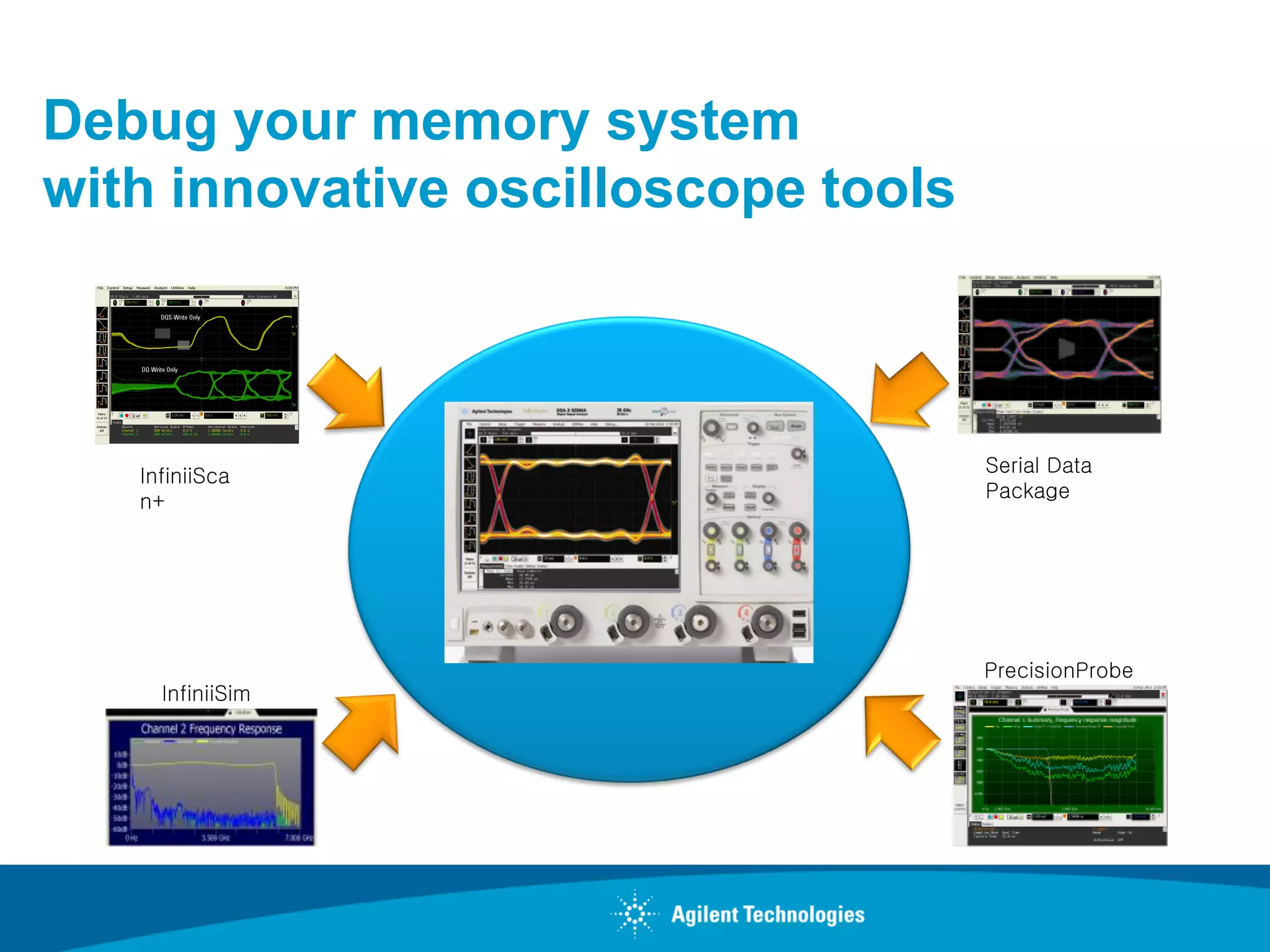
The document discusses challenges in probing memory systems and introduces tools like PrecisionProbe fixtures and de-embedding software to maximize probe performance and provide accurate measurements by removing probing effects. It covers probing DDR memory at different design phases, how to trigger and measure signals, and techniques for analyzing measurements against JEDEC specifications.
Nov 12 Webcast: Eliminate Pitfalls of DDR Memory Testing
Join Teledyne LeCroy's, Mike Hertz, for this free webinar on using an oscilloscope for validation and debug of DDR2/3/4 physical layer measurements.
Topics covered will include: probing, connectivity, recommended device patterns, de-embedding, examples of good and bad waveforms, and debugging steps and techniques.
Mike Hertz has been a Field Applications Engineer with Teledyne LeCroy in Michigan for 14 years.
Totem Technologies for Analog, Memory, Mixed-Signal DesignsAnsys
Analog, mixed-signal and custom designs face unique challenges when it comes to power and reliability analysis. SRAM and FLASH memories are pushing the envelope to handle large designs, while mixed-signal and RF designs need concurrent analysis of large analog blocks with interspersed digital logic as well as substrate noise coupling. This presentation demonstrates how Totem, a single platform for Power Noise and Reliability, can be used to address the unique challenges for analog, mixed-signal and custom designs. Learn more on our website: https://bit.ly/1qk5Juj
Benefits of enhanced event analysis in datacenter otdr testingFangXuIEEE
Automatic detection and analysis algorithm of events in OTDR traces is very a challenging signal processing and analysis problem. It has too many tradeoffs to overcome: sensitivity vs. reliability, complexity vs. execution time. Traditional signal processing methods quickly reach performance limits. This is a place to demonstrate peoples creativity of finding exotic algorithm and method.
Aq7275 Hướng dẫn sử dụng máy đo sợi cáp quang Yokogawa otdrMr Calvin Pham
Máy đo sợi cáp quang OTDR model AQ7275 là dòng máy đo chuẩn và chính xác trên thị trường. Tuổi thọ Pin của máy đo cao, dễ dàng thay thế và sữa chữa
tham khảo chi tiết tại : www.phukienquang.net
Nowadays, mobile consumer electronics devices integrate various wireless interfaces like WIFI, Bluetooth, GPRS and GPS. Various approaches exist to protect the wireless interfaces against ESD stress. In recent years, researchers have focused on so‐called 'co‐design' techniques to solve both functional and protection constraints together which requires both RF and ESD design skills. However many IC designers still prefer to work with 'plug‐n‐play' protection concepts where the ESD clamps exhibit low parasitic capacitance, low series resistance and low leakage. This paper presents measurement results of 3 different SCR based protection approaches that exhibit high Q‐factor and low and stable parasitic capacitance over a broad voltage and frequency range. The clamps are used for protection of LNA circuits in 90nm and 40nm Low Power (LP) CMOS technologies.
Advantages of Ultrasonic Thickness Gages over Flaw Detectors for Corrosion Th...Olympus IMS
This presentation highlights the advantages of modern ultrasonic thickness gages for making corrosion thickness measurements. This information focuses on certain features that make thickness gages better suited than ultrasonic flaw detectors for this type of application.
Presenter:
Greg Bauer is a Product Specialist for ultrasonic thickness gages and transducers. He has several years' experience providing global technical and application support, training, and application development for the thickness gage and transducer product lines.
GORE Microwave / RF Assemblies
You can view more sales informations in "www.frandnew.com"
Friends, did you forgive your dreams, too?
Then, only make your letters!
I made a direct online referral business letter platform
for millions of buyer and seller who have seeked for global business informations.
If you want more communication with me, email to me.
E-mail : groomofghost@gmail.com
Final stage of marketing. Let's be friends!
= Frand New =
DFX Architecture for High-performance Multi-core MicroprocessorsIshwar Parulkar
This presentation was given at ITC 2008 (International Test Conference). It deals with DFX challenges and solution for high count multi-core microprocessors. Acknowledgment: Co-authors on ITC presentation - Gaurav Agarwal, Sriram Anandakumar, Gordon Liu, Rajesh Pendurkar, Krishna Rajan and Frank Chiu.
What Can FPGA Designers Do With Personal Data Centers?plunify
These are the slides presented by Plunify during the event, "Accelerate Time-To-Market Using Cloud Computing", held on 14th Oct 2011, organized by the Singapore Semiconductor Industry Association.
Overview of the BF609 dual-core Blackfin processor series covering main features including the Pipelined Vision Processor including the hardware and software development tools. By Analog Devices
Waupaca County and Trempealeau County have both been running ArcGIS server (AGS) web mapping applications since late 2007. The two Counties worked together throughout the implementation process. They hope to share how to plan for an AGS implementation and potential pitfalls to avoid. The session is intended to be a starting point for users planning to implement AGS web mapping applications. Topics covered will be relevant
to software versions 9.2 and 9.3.
In this talk, we describe the latest trends and advancements in storage-class memory (a.k.a. Non-Volatile Memory) and its impact on data infrastructure as it exists today. We also describe how Ampool is building a product that allows Big Data analysis solutions to work together with a smart storage class memory layer to allow fast & complex end to end analytical pipelines, thus lowering the time-to-insights significantly.
How to Create Map Views in the Odoo 17 ERPCeline George
The map views are useful for providing a geographical representation of data. They allow users to visualize and analyze the data in a more intuitive manner.
Instructions for Submissions thorugh G- Classroom.pptxJheel Barad
This presentation provides a briefing on how to upload submissions and documents in Google Classroom. It was prepared as part of an orientation for new Sainik School in-service teacher trainees. As a training officer, my goal is to ensure that you are comfortable and proficient with this essential tool for managing assignments and fostering student engagement.
Model Attribute Check Company Auto PropertyCeline George
In Odoo, the multi-company feature allows you to manage multiple companies within a single Odoo database instance. Each company can have its own configurations while still sharing common resources such as products, customers, and suppliers.
Students, digital devices and success - Andreas Schleicher - 27 May 2024..pptxEduSkills OECD
Andreas Schleicher presents at the OECD webinar ‘Digital devices in schools: detrimental distraction or secret to success?’ on 27 May 2024. The presentation was based on findings from PISA 2022 results and the webinar helped launch the PISA in Focus ‘Managing screen time: How to protect and equip students against distraction’ https://www.oecd-ilibrary.org/education/managing-screen-time_7c225af4-en and the OECD Education Policy Perspective ‘Students, digital devices and success’ can be found here - https://oe.cd/il/5yV
2024.06.01 Introducing a competency framework for languag learning materials ...Sandy Millin
http://sandymillin.wordpress.com/iateflwebinar2024
Published classroom materials form the basis of syllabuses, drive teacher professional development, and have a potentially huge influence on learners, teachers and education systems. All teachers also create their own materials, whether a few sentences on a blackboard, a highly-structured fully-realised online course, or anything in between. Despite this, the knowledge and skills needed to create effective language learning materials are rarely part of teacher training, and are mostly learnt by trial and error.
Knowledge and skills frameworks, generally called competency frameworks, for ELT teachers, trainers and managers have existed for a few years now. However, until I created one for my MA dissertation, there wasn’t one drawing together what we need to know and do to be able to effectively produce language learning materials.
This webinar will introduce you to my framework, highlighting the key competencies I identified from my research. It will also show how anybody involved in language teaching (any language, not just English!), teacher training, managing schools or developing language learning materials can benefit from using the framework.
How to Split Bills in the Odoo 17 POS ModuleCeline George
Bills have a main role in point of sale procedure. It will help to track sales, handling payments and giving receipts to customers. Bill splitting also has an important role in POS. For example, If some friends come together for dinner and if they want to divide the bill then it is possible by POS bill splitting. This slide will show how to split bills in odoo 17 POS.
Unit 8 - Information and Communication Technology (Paper I).pdfThiyagu K
This slides describes the basic concepts of ICT, basics of Email, Emerging Technology and Digital Initiatives in Education. This presentations aligns with the UGC Paper I syllabus.
Read| The latest issue of The Challenger is here! We are thrilled to announce that our school paper has qualified for the NATIONAL SCHOOLS PRESS CONFERENCE (NSPC) 2024. Thank you for your unwavering support and trust. Dive into the stories that made us stand out!
1. Debug your memory system
with innovative oscilloscope tools
Serial Data
InfiniiSca
Package
n+
PrecisionProbe
InfiniiSim
2. Agenda
Probing Challenges
• De-embed probing effect for accurate measurement
• PrecisionProbe for maximizing probe performance
DDR memory SI design phases and testing
Trigger and Measure
• Read and Write Data
• Eye Diagram measurement
Analyze
• Make measurement and verify against JEDEC spec.
• Run automated measurement to save time.
3. Key Memory Design Challenges
Faster Data Rate Compact/Small Board Design
SI verification Less probing space
- stricter rule in platform design - Signal accessibility is
Margin testing limited
- System requires more system Less probing options
margin - Conventional probing limits
Probe load signal insights
- Probe load reduces system margin
DDR Speed Transition
3200
SI testing is essential for
High speed data rate DDR4
Data rate(MT/s)
2133
DDR3 1866
1600
1333
DDR2 1066
800
DDR1 633 667
400
High density board design:
333
200 Where to probe?
4. Agenda
Probing Challenges
• De-embed probing effect for accurate measurement
• PrecisionProbe for maximizing probe performance
DDR memory SI design phases and testing
Trigger and Measure
• Read and Write Data
• Eye Diagram measurement
Analyze
• Make measurement and verify against JEDEC spec.
• Run automated measurement to save time.
5. Probing Challenges
Probing at transmission lines or surface mount components cause signal
reflection and other SI issues
Probing at the wrong location causes
reflection, resulting in non-monotonic
edges. This will cause error in your tests
such slew rate, setup and hold time
Midbus probing measurements.
• Non ideal for SI
test Load on probing affects the signals on your
system as well as what you measure.
6. How do I probe my memory signals?
If vias are accessible: If vias are NOT accessible:
For BGA package, probing at For embedded system with
the via close to the balls of the tight board spaces and fully
DDR DRAM generally gives you populated DIMM
the best results since the JEDEC configuration, BGA probes
standard is defined at the balls provide signal access
Fully populated DIMM
of the DRAM.
• No vias to probe
BGA probe on DIMM
configuration
BGA probe on
embedded board
design
Concern with BGA probing:
Does BGA probe affects the SI of my board?
7. BGA probe and Via probing Comparison – Before
de-embedding
Flex wing BGA probe with
Scope optimized BGA probe adapter board
Channel 1: Probing at VIA
Channel 2: Probing at scope pad point on
adapter board
Channel 1: Probing at VIA (under the Decrease in
DRAM) amplitude
Channel 2: Probing at scope pad
point
Skew
caused by
delay
Skew caused by
delay Measurement distorted for SI check:
Good for SI check: Signal performance is affected
High bandwidth probe allows for using the BGA probe for SI check.
How do I simulate an ideal probe?
8. Oscilloscope de-embed tool - InfiniiSim
Physical layout of a board InfiniiMax probe head
Memory Controller DRAM
BGA probe
Delay
Memory Simulation
DRAM
InfiniiSim - General Purpose 9 Blocks Topology
Controller
BGA probe
S parameter
file
InfiniiMax
probe head
s1p file
Measurement
10. Oscilloscope de-embed tool – After de-embedding
Channel 1: Probing at VIA (DQS strobe) Channel 1: At VIA (DQS strobe)
Channel 2: Probing at scope pad point Channel 2: At scope adapter board
Turn on Bandwidth Limit to 4G on
Signal at BGA probe is identical to signal probing at the channel to reduce the ringing
via. Measurement result is not compromised by the effect due to high frequency
content.
probing effect.
11. DDR3 BGA Probe Optimum Bandwidth
DDR3 BGA probe is the most common
probe used in DRAM probing
Concerns:
• DDR3/4 data rate is increasing to > 2GB/s
• Probing effect affects SI measurement
DRAM
Nominal BW for BGA probe is between 1.5 and 2 GHz
before probe correction
DDR3 BGA probe DRAM soldered on to
with scope pads for DDR3 BGA probe
signal accessibility and system test
12. DDR3 BGA Probe Correction Method
1. Apply solder bumps to all of the ground (VSS)
connections on the outer rows of the interposer.
2. Planarize/Level the solder bumps with a large VSS Signal for
piece of ceramic. correction
3. Cut out two pieces of z-axis connection
material, elastomer contact.
4. With a microscope, align the BGA probe VSS
above the thru fixture so that only the signal ball
contacts the transmission line and all of the
ground balls contact ground.
DDR BGA probe
Solder ball
Elastomer
Thru fixture
Signal contacts
VSS (ground) transmission line on
contacts ground Signal of interest contacts
transmission line on thru thru fixture
on thru fixture
through elastomer fixture through elastomer
13. PrecisionProbe Fixture Setup
5. Connect the thru fixture to the channel
input of the oscilloscope and feed CAL out
from the oscilloscope to the thru fixture with
Vin
a SMA cable.
6. Solder the probe head to the oscilloscope
pads on the BGA probe and connect to one
of the channel inputs.
•Vin is defined as the signal at the BGA
probe point while the signal is being loaded
by the BGA probe.
•Vout is the signal that is output from the
BGA probe.
•Vout/Vin Correction, the signal at the
output of the probe is an accurate
representation of the signal that currently
exists, as it is being probed
Thru fixture with BGA probe ready for calibration
with the scope
14. PrecisionProbe Calibration
6. PrecisionProbe Wizard
PrecisionProbe and Cable provide an easy to follow guide with its wizard. The wizard
takes you step by step through the set up of the software and ensures that your
measurements are taken with the highest signal integrity.
Bandwidth control
allows you to
remove unwanted
high frequency
noise by providing
a filter.
Save and Recall the
PrecisionProbe calibration result.
15. Corrected Probe Response
Probe Input Impedance
Knowing the impedance profile of the
probe allows you to estimate the loading
of the probe system.
The BGA probe response corrected to close to 10GHz
16. Real Time Eye Diagram Measurement
GDDR5 Write DQ Real Time Eye Diagram
Unfold real time eye to find DQ mask violat
Without de-embedding
De-embed DQ
cleared mask test
Non de-embed
With de-embedding DQ violated
mask test
17. Agenda
Probing Challenges
• De-embed probing effect for accurate measurement
• PrecisionProbe for maximizing probe performance
DDR memory SI design phases and testing
Trigger and Measure
• Read and Write Data
• Eye Diagram measurement
Analyze
• Make measurement and verify against JEDEC spec.
• Run automated measurement to save time.
18. SI Measurement with Oscilloscope
Memory Design Phases that requires SI testing
Prototyping (alpha and
beta) Post Production
•SI characterization to • Margin testing for checking
compare results with compatibility issues
design simulation and
specification
•Margin testing – varying
temperature and voltage
levels
SI Validation Tasks (Trigger and Measure)
•Read and write data parametric testing
•Identify cross talk and ISI failures
•Track infrequent events
•Jitter characterization
•Compliance as per JEDEC standard
19. How do I trigger on a Read/Write Data
DDR2/3 Read and Write Burst (DQS) with Data (DQ)
Two distinctive read and write burst
patterns
DQ
DQ Eye diagram S
DQ0
Idle Read and Write
state data
Read and Write eye
overlapping
20. Oscilloscope Zone Qualify Trigger – InfiniiScan+
Zone 1 – Must not Intersect to eliminate Idle State
Zone 2 – Must Intersect to trigger on Read DQS to get read Data
Zone 2 DQS
Zone 1
DQ0
Read DQS is edge aligned with Read DQ
21. Eye Diagram Test after Read/Write Separation
Eye Diagram Test
• Allows measurement of eye
height and width to measure
Data eye height and width
• User can also define own
mask as per device
specification
22. Mask Test Failure
Find failure edge and perform SI measurement
DQ Mask
Violation
• Measure the timing relationship between
Unfold Eye and navigate to failure position signals (such as Clock and DQS signals)
• Measure signal integrity
• Rise/fall time
• Slew rate
• Amplitude
• Overshoot/Ringing
• Find patterns on DQ signals for ISI related
problems.
23. How do I trigger on a read/write command?
GDDR5 Command Truth Table GDDR5 Memory
GDDR5 Memory Signals Signals
CAS#
WE#
WCK/WCK#
DQ
READ: CAS# = Low, WE# = High
WRITE: CAS# = Low, WE# = Low
There’s no distinctive read/write burst
Load FIFO, Deselect, Refresh, Self Refresh, patterns
Power Down: CAS# = X, WE# = X
24. Oscilloscope Zone Qualify Trigger – InfiniiScan+
Trigger on Write command on GDDR5
signals
CAS#
Trigger Steps:
1. Trigger on falling edge of Zone1
CAS
WE#
2. Zone 1 – Must Not Intersect Zone 2
to trigger on first burst
(CAS=Low)
WCK/WCK#
3. Zone 2– Must Intersect to
trigger on WE = Low (write
command)
DQ
4. Zone 3 – Must intersect to Zone 3
trigger on Write data transition
and to eliminate Hi state of
data caused by other
commands – Self refresh,
Power Down..etc Use only 4 channels to do read/write command trigger
25. Oscilloscope Zone Qualify Trigger – InfiniiScan+
Determine the Write latency of the GDDR5 write
command
CAS#
Zone1
WE#
Zone 2
WCK/WCK#
DQ
Write Latency = 4 CK cycles
Or 8 WCK cycles Zone 3
Quickly determine the read/write latencies of the DRAM with Command trigger
26. Measurement – Eye Diagram
GDDR5 eye diagram measurement to determine data valid
window
A successful
read/write separation
enables data valid
window measurement
on multiple edges
27. Trigger Signal Pattern On screen – InfiniiScan +
Potential SI problem due to reflection
DQ0
Concern:
There’s only one signal, DQ0 available for probing,
I can see the potential issue on screen, can I trigger?
28. Measurement – Real Time Eye Diagram
Turn on Real-Time eye to ensure
Zone 1: Must data valid window spec is not
intersect to compromised:
trigger on signal with
Reflection due to imperfect
SI issue only
termination found.
DQ0
Eye Width and Height measurement
29. Track Specific Pattern with InfiniiScan Zone Trigger
Trigger data “010000101010” with
InfiniiScan
1 2
Allows more robust
data pattern test:
• Measure SI (rise
time,
overshoot/undershoo
t amplitude) during
rigorous data
3 4 transitions.
DQ =
“010000101010” Group/Presentation Title
Agilent Restricted
Page 29 Month ##, 200X
30. Agenda
Probing Challenges
• De-embed probing effect for accurate measurement
• PrecisionProbe for maximizing probe performance
DDR memory SI design phases and testing
Trigger and Measure
• Read and Write Data
• Eye Diagram measurement
Analyze
• Make measurement and verify against JEDEC spec.
• Run automated measurement to save time.
31. Analyze
Make measurement and verify against JEDEC specification
JEDEC spec: DDR3 Write Pre-amble width - tWPRE
DDR3 Write Pre-amble width - tWPRE
JEDEC spec: DDR3 Data Setup Time- tDS
DDR3 Data Setup Time- tDS
Concern with making manual
measurements:
Tedious and time consuming, repeatability
issues
32. Analyze with Automated Compliance Test
Perform Electrical, Clock and Timing tests
HTML Test Report with measurement details
Automated tDS test with
measurement result
indicating pass/fail
status as per JEDEC
spec
33. AC150/AC175 Levels Setup
Automatically load
AC level test limits
for different speed
grade
Example:
The tIS(base) AC150 specifications are
adjusted from the tIS(base) specification by
adding an additional 100 ps of derating to
accommodate for the lower alternate
threshold of 150 mV
JEDEC 3E tIS and tIH test limits
34. Custom Derating Table for Characterization
DDR Derated Command/Address and Data Tests Custom Derating table support
Example: tIS (total setup time) = tIS(base) + ΔtIS
Note: ΔtIS is determined from the derating table Editable DeratingAndBaseTable.dat
35. Automated Threshold Settings for DDR
Characterization
“Set”
automatically
calculate the
Vref and VTT
voltages
Wizard for
voltage
threshold
settings
Measurement
threshold applies to
Single
Ended/Differential
Input/Output signals
The intuitive GUI in the automated compliance app
allows for measurement of non-standard DDR
voltage levels. For example, 1.25V.
36. Multi-Burst Measurement for Statistical Analysis
4 sets of bursts found in one single acquisition
Multi-burst measurement
allows measurement of
multiple bursts in a single
acquisition or multi
acquisition for statistical
analysis – Min, Max, Mean,
Stdev
37. Margin testing with Compliance Test
Compliance test report enables margin reporting
Check for compatibility and
margin allowance
• Use a standard
measurement methodology
for repetitive testing with
variance of temperature and
voltage.
• Compile test result/report on
margin for finding optimal
performance.
38. Testing eMMC with User Defined Application
Create your own eMMC Compliance Test with UDA
1. Users Download the FREE
development environment
Processor
Baseband + Application 2. User install the DE on their
scope or PC and develop
their UDA
3. Application is then
generated and installed
ROM RAM on the scope
eMMC LPDDR2
4. Application then runs
on the oscilloscope
with “Run License” and
test report is generated
39. eMMC JEDEC spec as Reference
Sequence of SCPI
commands to perform
Clock timing tests
eMCC spec from JESD84-A441
40. Summary
Probing Technologies
• DRAM BGA probe used when vias are not
accessible
• InfiniiSim and PrecisionProbe for
maximizing probe performance
SI Testing/Characterization with
Oscilloscope
InfiniiScan+
• Read and Write Data for eye diagram
measurement
DDR automated compliance app
Run automated measurement to save time.
Additional features to perform statistical
analysis and margin testing for
characterization purposes
• Multi-burst measurement
• Customized Derating table
• Automated voltage threshold setting
• UDA
41. Memory Oscilloscope Measurement Tool
DRAM
DDR Compliance DDR Fixtures
Software and Probes
Packages
(clock, electrical
and timing tests)
InfiniiScan InfiniiSim Serial Data PrecisionProbe
+ Package
9000/90000 series Oscilloscope