This research analyzes the modeling and efficiency of a wireless power transfer (WPT) system using magnetic resonance coupling, focusing on a series-parallel-mixed topology. The study employs circuit theory to assess power transfer efficiency, revealing that the model achieves higher efficiency at low coupling factors. Simulation results indicate an efficiency of approximately 80.48% for input voltages of 100V and 110V peak-to-peak at a frequency of 365.1 kHz.
![Indonesian Journal of Electrical Engineering and Computer Science
Vol. 6, No. 3, June 2017, pp. 563 ~ 571
DOI: 10.11591/ijeecs.v6.i3.pp563-571 563
Received January 18, 2017; Revised April 15, 2017; Accepted May 1, 2017
Modelling and Efficiency-Analysis of Wireless Power
Transfer using Magnetic Resonance Coupling
Masood Rehman*, Zuhairi Baharudin, Perumal Nallagownden, Badarul Islam
Department of Electrical and Electronics Engineering, Universiti Teknologi PETRONAS, Seri Iskandar,
32610, Perak, Malaysia
*Corresponding author, e-mail: masood.rehman@hotmail.com
Abstract
Wireless power transfer (WPT) system has got significant attention in recent years due to its
applications in consumer electronics, medical implants and electric vehicles etc. WPT is a promising
choice in situations, where the physical connectors can be unreliable and susceptible to failure. The
efficiency of WPT system decreasing rapidly with increasing air-gap. Many circuit topologies have been
employed to enhance the efficiency of the WPT system. This paper presents the modelling and
performance analysis of resonant wireless power transfer (RWPT) system using series-parallel-mixed
topology. The power transfer efficiency analysis of the model is investigated via circuit theory. S-
parameters have been used for measuring power transfer efficiency. Transient analysis is performed to
realize the behavior of voltage and current waveforms using advanced design system (ADS) software. The
proposed model is tested with two amplitudes i.e. 100 V peak-to-peak and 110 V peak-to-peak at the same
frequency of 365.1 kHz. The overall result shows that the series-parallel-mixed topology model has higher
efficiency at low coupling factor (K) for both voltage amplitudes.
Keywords: Wireless power transfer, Resonant wireless power transfer, Power transfer efficiency analysis,
Transient analysis
Copyright © 2017 Institute of Advanced Engineering and Science. All rights reserved.
1. Introduction
Wireless power transfer (WPT) Wireless power transfer (WPT) is the method of
transferring the electrical power from supply to load without using physical connectors. The idea
of wireless power transfer was given by Nikola Tesla about a century ago [1]. WPT technology
can have an adequate impact on the environment because the use of wires and batteries can
be reduced significantly by using this technology. According to the power transfer mechanism,
there are two types of WPT i.e. radiative or non-radiative. Radiative power relies on far-field and
it can be defined as the transfer of electrical energy through a medium such as air using a
transmitting coil over a long distance as an electromagnetic wave [2]. This approach of WPT is
used for industrial, scientific, defense and medical purposes [3]. The non-radiative wireless
power transfer employs near-field inductive or resonant coupling and is suitable for short-range
and mid-range applications. The radiative power includes microwave and laser technology.
Nevertheless, the remarkable research has been carried out in the field of radiative WPT, still
this radiative approach suffers from the trade-off between directionality and transmission
efficiency [4]. Moreover, the radiative approach of transferring power is hazardous for human
health therefore it is not a prevalent choice.
Recent research in non-radiative WPT has outlined the potential benefits and methods
of wireless power transfer using inductive coupling and magnetic resonant coupling. The WPT
system using inductive coupling works like the basic transformer, which uses electromagnetic
induction method for transferring the power from primary to secondary coil and can be called as
inductive wireless power transfer (IWPT). In a transformer the magnetic field is typically
confined to a high permeability core. However in IWPT technique, the region between the
primary and secondary coils can be simply air or vacuum [5]. The WPT using magnetic coupled
can be called as resonant wireless power transfer (RWPT). Magnetic resonance coupling can
be created by using self-resonance of the spiral conductors, which resonates with its self-
inductance and parasitic capacitance. But when the parasitic capacitance of the conductors are
insufficient to make resonance at desired frequency, an external capacitor can be added to](https://image.slidesharecdn.com/1016099paper093ijeecseditnew-201014032908/85/10-16099-paper-093-ijeecs-edit-new-1-320.jpg)
![Indonesian Journal of Electrical Engineering and Computer Science
Vol. 6, No. 3, June 2017, pp. 563 ~ 571
DOI: 10.11591/ijeecs.v6.i3.pp563-571 563
Received January 18, 2017; Revised April 15, 2017; Accepted May 1, 2017
Modelling and Efficiency-Analysis of Wireless Power
Transfer using Magnetic Resonance Coupling
Masood Rehman*, Zuhairi Baharudin, Perumal Nallagownden, Badarul Islam
Department of Electrical and Electronics Engineering, Universiti Teknologi PETRONAS, Seri Iskandar,
32610, Perak, Malaysia
*Corresponding author, e-mail: masood.rehman@hotmail.com
Abstract
Wireless power transfer (WPT) system has got significant attention in recent years due to its
applications in consumer electronics, medical implants and electric vehicles etc. WPT is a promising
choice in situations, where the physical connectors can be unreliable and susceptible to failure. The
efficiency of WPT system decreasing rapidly with increasing air-gap. Many circuit topologies have been
employed to enhance the efficiency of the WPT system. This paper presents the modelling and
performance analysis of resonant wireless power transfer (RWPT) system using series-parallel-mixed
topology. The power transfer efficiency analysis of the model is investigated via circuit theory. S-
parameters have been used for measuring power transfer efficiency. Transient analysis is performed to
realize the behavior of voltage and current waveforms using advanced design system (ADS) software. The
proposed model is tested with two amplitudes i.e. 100 V peak-to-peak and 110 V peak-to-peak at the same
frequency of 365.1 kHz. The overall result shows that the series-parallel-mixed topology model has higher
efficiency at low coupling factor (K) for both voltage amplitudes.
Keywords: Wireless power transfer, Resonant wireless power transfer, Power transfer efficiency analysis,
Transient analysis
Copyright © 2017 Institute of Advanced Engineering and Science. All rights reserved.
1. Introduction
Wireless power transfer (WPT) Wireless power transfer (WPT) is the method of
transferring the electrical power from supply to load without using physical connectors. The idea
of wireless power transfer was given by Nikola Tesla about a century ago [1]. WPT technology
can have an adequate impact on the environment because the use of wires and batteries can
be reduced significantly by using this technology. According to the power transfer mechanism,
there are two types of WPT i.e. radiative or non-radiative. Radiative power relies on far-field and
it can be defined as the transfer of electrical energy through a medium such as air using a
transmitting coil over a long distance as an electromagnetic wave [2]. This approach of WPT is
used for industrial, scientific, defense and medical purposes [3]. The non-radiative wireless
power transfer employs near-field inductive or resonant coupling and is suitable for short-range
and mid-range applications. The radiative power includes microwave and laser technology.
Nevertheless, the remarkable research has been carried out in the field of radiative WPT, still
this radiative approach suffers from the trade-off between directionality and transmission
efficiency [4]. Moreover, the radiative approach of transferring power is hazardous for human
health therefore it is not a prevalent choice.
Recent research in non-radiative WPT has outlined the potential benefits and methods
of wireless power transfer using inductive coupling and magnetic resonant coupling. The WPT
system using inductive coupling works like the basic transformer, which uses electromagnetic
induction method for transferring the power from primary to secondary coil and can be called as
inductive wireless power transfer (IWPT). In a transformer the magnetic field is typically
confined to a high permeability core. However in IWPT technique, the region between the
primary and secondary coils can be simply air or vacuum [5]. The WPT using magnetic coupled
can be called as resonant wireless power transfer (RWPT). Magnetic resonance coupling can
be created by using self-resonance of the spiral conductors, which resonates with its self-
inductance and parasitic capacitance. But when the parasitic capacitance of the conductors are
insufficient to make resonance at desired frequency, an external capacitor can be added to](https://image.slidesharecdn.com/1016099paper093ijeecseditnew-201014032908/75/10-16099-paper-093-ijeecs-edit-new-1-2048.jpg)
![ ISSN: 2502-4752
IJEECS Vol. 6, No. 3, June 2017 : 563 – 571
564
build the resonance conductors [6]. In the RWPT technique, the leakage inductance is
compensated by combining the techniques of magnetic coupling and resonance together to
ensure the improved power transfer efficiency.
After the Tesla’s experiments, there has been little research on wireless power transfer
since several decades. In the late 20th century, the IWPT technology received significant
attention from the researchers [7] and the wireless charging of portable consumer devices was
initially commercialized for charging small electric devices like tooth brushes, cell phones [8]
and other similar devices. Furthermore, the IWPT method has also been deployed for high
power applications in kilowatts (KW) range, such as charging of electric vehicles [9]. After the
wireless charging is standardized universally, the market of wireless charging has been grown
rapidly. In the year 2007, RWPT technology caught the world’s attention, when the team of
researchers at Massachusetts Institute of Technology (MIT) developed a magnetic resonant
coupled scheme to enhance the transmission efficiency [10, 11]. They demonstrated the
feasibility of WPT by using two self-resonant high quality factor (Q= 950) spiral coils with radius
30cm to light a 60W bulb with 2m air gap. The experiment was successful with transfer
efficiency of 40% to 60% [11, 12].
Presently, many researchers are working on the enhancement of efficiency and air-gap
of RWPT technology. The efficiency of RWPT systems decreases drastically with increasing air-
gap and misalignment between transmitter and receiver coils. The research on misalignment of
coils is presented in [13-15], which concluded that the misalignment can significantly impair the
power transfer efficiency and the efficiency can be improved by optimizing the design of coil. A
lot of interesting works have been accomplished with different kinds of innovative circuits as well
as the system analysis and control in [5, 11, 16-18]. The detailed discussion has been
presented for multi-dimensional WPT structure in [19]. Furthermore, the frequency splitting
phenomenon frequently occurs in the WPT systems with multi-transmitter and multi-receiver
coils, when two or more adjacent coils are in close vicinity that they have strong relative
magnetic fields. This phenomenon of splitting frequency has been discussed and analyzed in
[20]. Furthermore, in [21], it is concluded that the maximum distance between transmitter and
receiver is related to the radius and number of turns of the coils. The operation of RWPT system
with multiple transmitters and receivers is investigated in [22]. It was examined that due to
multiple couplings, the actual resonant frequency of the transmitter or the receiver are altered.
In order to compensate the alteration of frequencies, the necessary adjustments are provided.
By utilizing the proposed frequency adjustments, 51 to 65 W powers are transferred with
efficiency of 45% to 57% at coupling coefficients of 0.025 to 0.063, respectively.The research
reported in [23] proposed an optimizable WPT model for acquiring high power transfer
efficiency. The efficiency of 85% for the air-gap of 10 centimeters and the efficiency of 45% for
the air-gap of 20 centimeters was realized. In [24] ,the authors have conducted research on
WPT with metamaterial. From the computational results they relalized that the range of power
transfer can be increased using WPT with metamaterial.The focus of their research was only on
range but the efficiency was not discussed. While the work presented in this paper discusses
the efficiency as well as frequency analysis.
This paper presents the modelling and efficiency analysis of wireless power transfer
using magnetic resonance coupling. Initially, the expressions of the model are achieved by
circuit theory. Thereafter, simulation of series-parallel-mixed topology is performed by advanced
design system (ADS) software. S-parameter and transient analysis of the model are carried out
to analyze the performance of the model.
2. Research Method
This section consists of three sub-sections, which are given below.
2.1. Power Transfer Efficiency Analysis
In order to carry out the power transfer efficiency analysis, the series-parallel-mixed
topology model is illustrated in Figure 1. Note that WPT system needs high frequency (HF)
alternating current (AC) supply. HF AC supply can be created by using an inverter and power
amplifier or inverter and oscillator.](https://image.slidesharecdn.com/1016099paper093ijeecseditnew-201014032908/85/10-16099-paper-093-ijeecs-edit-new-2-320.jpg)
![IJEECS ISSN: 2502-4752
Modelling and Efficiency-Analysis of WPT using Magnetic Resonance … (Masood Rehman)
565
Figure 1. Series-parallel-mixed circuit model of two coils WPT system
According to S-parameters, which are often called scattering parameters, the function of
power transfer efficiency is expressed as,
| | (1)
The expression of magnitude (S21) has been derived by Chen et al. [23], which is given
by,
| | √ √ (2)
where, Us is the source voltage applied on the transmitting coil at resonance frequency
ω, and RS and RL are the source and load resistances of transmitting and receiving coils,
respectively. The expressions for α,β and γ are given by (3), (4) and (5), respectively.
(3)
( )
(4)
√ ( )
( )( )
(5)
In the above equations R1 and R2 are the characteristic resistances of transmitting and
receiving coils, respectively. Now, the equation of efficiency ƞ can be achieved by substituting
the value of | | in (1) and is given by (6).
( √ ) (6)
By using the equivalent circuit method, the voltages and efficiency can be calculated.
From (6), it can be extracted that efficiency is associated with the parameters such as coupling
factor K, resonance frequency ω, resistances, capacitances and inductances of the coils.
Therefore, by tuning the above circuit parameters efficiency can be improved. Furthermore,
Impedance matching and adaptive shifting frequency method can be used to improve the
efficiency. Additionally, the two operating principles of WPT are suggested in the literature, i.e.
maximum power transfer principle or maximum energy efficiency principle.
Maximum power transfer theorem permits a flexible control of impedance matching in
the model by adjusting two extra coupling coils to enhance the air gap, but in this case efficiency
will be compromised. If the relay resonators or domino resonators between the source and the
load are deployed, a good compromise between efficiency and air gap can be achieved, by](https://image.slidesharecdn.com/1016099paper093ijeecseditnew-201014032908/85/10-16099-paper-093-ijeecs-edit-new-3-320.jpg)
![ ISSN: 2502-4752
IJEECS Vol. 6, No. 3, June 2017 : 563 – 571
566
using the maximum energy efficiency principle [2]. Furthermore, according to the research
reported in [25] there is a critical coupling parameter for distance known as the point of critical
coupling Kcritical, apart from that point the system cannot operate a given load at the maximum
efficiency. In series resonant model, when the system is symmetrical, i.e. R1=R2=Rx and
RS=RL=R; Then Kcritical and S21 (critical) is given by (7) and (8) respectively;
(7)
( ) (8)
From the above equations, it can be seen that Kcritical is dependent on ωL and the load
resistance. For this reason, the series-series model is not capable of transferring power at large
distance. It is worth mentioning that both series and parallel topology models have their own
advantages and disadvantages. The series-series circuit model can give the higher value of
maximum transfer efficiency because of the lower sensitivity for the parasitic resistance.
Moreover, the transfer distance can be increased by increasing inductor value of series-series
model, but it will lead to decrease the efficiency because of larger parasitic resistance loss of
large-sized coils. On the other hand, the parallel-parallel circuit model has ability to overcome
the flaws of series-series circuit model. But parallel-parallel topology model has its own
limitations, as it is bound to the parasitic resistance and its efficiency is seriously affected by an
increase in the L/C ratio [23]. Therefore, by mixing series and parallel topologies, the
advantages of both can be achieved to enhance the overall performance of WPT system.
2.2. Frequency Analysis
The present situation of high frequency in the resonant wireless power transfer (RWPT)
system creates the problems, because it is difficult to generate high frequency (HF) alternating
current (AC) supply. Therefore, it is of great importance to reduce the resonant frequency to get
easy excess to power electronics inverters. It is worth noting that when the resonance condition
occurs, the reactive impedance of the coil becomes zero, In that condition, the resonance
frequency of the transmitting and receiving coils can be calculated as,
√
(9)
The coupling factor (K) between the transmitting and the receiving coils mutual
inductance (M) between the transmitting and the receiving coils is formulated in terms of
coupling factor (K) and inductances of coils, which is given by (10),
√
(10)
From (9), it can be comprehended that the operating frequency can be decreased by
increasing the inductance or the capacitance without changing the condition of resonance.
When inductance value is changed it actually affects the coupling factor according to (10).
Therefore, it is essential to choose an optimized value of inductance and capacitance in order to
maintain the constant efficiency.
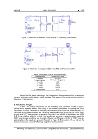
2.3. Design and Simulation of the Proposed Model
This section presents the modelling and simulation of series-parallel-mixed WPT
system using magnetic resonance coupling. The model is simulated for two input voltages i.e.
100 V peak-to-peak and 110 V peak to peak. Usually, the RWPT system requires a very high
frequency up to several MHz to get higher efficiency. But in this research, a comparatively low
frequency of 365.1 kHz is used, because implementation of a high frequency is difficult and it
has many losses. Figure 2 and Figure 3 show the schematic diagrams of model for performing
S-parameters and Transient analysis, respectively. The proposed circuit parameters are
provided in Table 1.](https://image.slidesharecdn.com/1016099paper093ijeecseditnew-201014032908/85/10-16099-paper-093-ijeecs-edit-new-4-320.jpg)
![ ISSN: 2502-4752
IJEECS Vol. 6, No. 3, June 2017 : 563 – 571
570
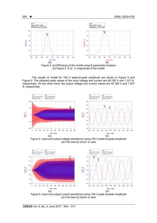
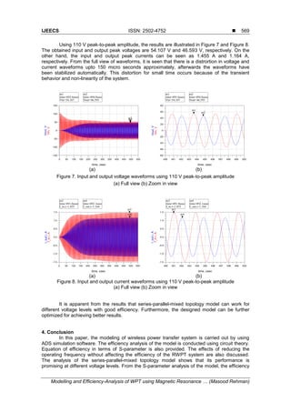
of about 80.48% is realized for two input amplitudes i.e. 100 V and 110 V peak-to-peak. Future
work may include the investigation on mid-range wireless power transfer by employing
impedance matching and adaptive shifting of frequency.
Acknowledgement
The authors would like to thank UniversitiTeknologi PETRONAS for providing research
fund to carry out this research.
References
[1] N Tesla. Apparatus for transmitting electrical energy. ed: Google Patents. 1914.
[2] SYR Hui, Z Wenxing and CK Lee. A Critical Review of Recent Progress in Mid-Range Wireless
Power Transfer. IEEE Transactions on Power Electronics. 2014; 29(9): 4500-4511.
[3] D van Wageningen and T Staring. The Qi wireless power standard. in Proceedings of 14th
International Power Electronics and Motion Control Conference EPE-PEMC. 2010.
[4] SD Barman, AW Reza, N Kumar, ME Karim and AB Munir. Wireless powering by magnetic resonant
coupling: Recent trends in wireless power transfer system and its applications. Renewable and
Sustainable Energy Reviews. 2015; 51: 1525-1552.
[5] BL Cannon, JF Hoburg, DD Stancil and SC Goldstein. Magnetic resonant coupling as a potential
means for wireless power transfer to multiple small receivers. IEEE Transactions on Power
Electronics, 2009; 24(7): 1819-1825.
[6] D Vilathgamuwa and J Sampath. Wireless Power Transfer (WPT) for Electric Vehicles (EVs)—
Present and Future Trends. in Plug In Electric Vehicles in Smart Grids, ed: Springer. 2015: 33-60.
[7] W Zhang, SC Wong, CK Tse and Q Chen. Analysis and comparison of secondary series-and
parallel-compensated inductive power transfer systems operating for optimal efficiency and load-
independent voltage-transfer ratio. IEEE Transactions on Power Electronics. 2014; 29(6): 2979-2990.
[8] CE Greene, DW Harrist and MT McElhinny. Powering cell phones and similar devices using RF
energy harvesting. ed: Google Patents. 2007.
[9] J Sallán, JL Villa, A Llombart and JF Sanz. Optimal design of ICPT systems applied to electric
vehicle battery charge. IEEE Transactions on Industrial Electronics. 2009; 56(6): 2140-2149.
[10] A Karalis, JD Joannopoulos and M Soljačić. Efficient wireless non-radiative mid-range energy
transfer. Annals of Physics. 2008; 323(1): 34-48.
[11] A Kurs, A Karalis, R Moffatt, JD Joannopoulos, P Fisher and M Soljačić. Wireless Power Transfer via
Strongly Coupled Magnetic Resonances. Science. 2007; 317(5834): 83-86.
[12] B Zhu, J Li, W Hu, and X Gao. Review of Magnetic Coupling Resonance Wireless Energy
Transmission. International Journal of U-& E-Service, Science & Technology. 2015; 8(3).
[13] W Junhua, SL Ho, WN Fu and S Mingui. Analytical Design Study of a Novel Witricity Charger With
Lateral and Angular Misalignments for Efficient Wireless Energy Transmission. IEEE Transactions on
Magnetics. 2011; 47(10): 2616-2619.
[14] K Fotopoulou and BW Flynn. Wireless Power Transfer in Loosely Coupled Links: Coil Misalignment
Model. IEEE Transactions on Magnetics. 2011; 47(2): 416-430.
[15] T Linlin, Q Hao, H Xueliang, C Weijie and S Wenhui. A novel optimization means of transfer
efficiency for resonance coupled wireless power transfer. Indonesian Journal of Electrical
Engineering and Computer Science. 2013; 11(5): 2747-2752.
[16] A Kurs, R Moffatt and M Soljačić. Simultaneous mid-range power transfer to multiple devices. Applied
Physics Letters. 2010; 96(4): 044102.
[17] C Sanghoon, K Yong-Hae, SY Kang, L Myung Lae, L Jong-Moo and T Zyung. Circuit-Model-Based
Analysis of a Wireless Energy-Transfer System via Coupled Magnetic Resonances. IEEE
Transactions on Industrial Electronics. 2011; 58(7): 2906-2914.
[18] Z Yiming, Z Zhengming and C Kainan. Frequency Decrease Analysis of Resonant Wireless Power
Transfer. IEEE Transactions on Power Electronics. 2014; 29(3): 1058-1063.
[19] JI Agbinya and NFA Mohamed. Design and study of multi-dimensional wireless power transfer
transmission systems and architectures. International Journal of Electrical Power & Energy Systems.
2014; 63: 1047-1056.
[20] R Huang, B Zhang, D Qiu and Y Zhang. Frequency Splitting Phenomena of Magnetic Resonant
Coupling Wireless Power Transfer. IEEE Transactions on Magnetics. 2014; 50(11): 1-4.
[21] T Imura and Y Hori. Maximizing Air Gap and Efficiency of Magnetic Resonant Coupling for Wireless
Power Transfer Using Equivalent Circuit and Neumann Formula. IEEE Transactions on Industrial
Electronics. 2011; 58(10): 4746-4752.
[22] D Ahn and S Hong. Effect of coupling between multiple transmitters or multiple receivers on wireless
power transfer. IEEE Transactions on Industrial Electronics. 2013; 60(7): 2602-2613.](https://image.slidesharecdn.com/1016099paper093ijeecseditnew-201014032908/85/10-16099-paper-093-ijeecs-edit-new-8-320.jpg)
![IJEECS ISSN: 2502-4752
Modelling and Efficiency-Analysis of WPT using Magnetic Resonance … (Masood Rehman)
571
[23] L Chen, S Liu, YC Zhou, and TJ Cui. An optimizable circuit structure for high-efficiency wireless
power transfer. IEEE Transactions onIndustrial Electronics. 2013; 60(1): 339-349.
[24] LJ Yu. Finite Element Analysis of a Contactless Power Transformer with Metamaterial. Indonesian
Journal of Electrical Engineering and Computer Science. 2014; 12(1): 678-684.
[25] AP Sample, D Meyer and JR Smith. Analysis, experimental results, and range adaptation of
magnetically coupled resonators for wireless power transfer. IEEE Transactions on Industrial
Electronics. 2011; 58(2): 544-554.](https://image.slidesharecdn.com/1016099paper093ijeecseditnew-201014032908/85/10-16099-paper-093-ijeecs-edit-new-9-320.jpg)