The document describes the design and implementation of an efficient wireless power transfer system. The system aims to enhance efficiency by strengthening mutual coupling along the power transmission path using three resonating coils inserted between the transmitting and receiving coils. The receiving circuit is also conditioned to maximize power delivered to the load. Both simulation and experimental results show the proposed system achieves significantly higher efficiency compared to a conventional single-coil system, approaching thousands of times better efficiency.
![International Journal of Power Electronics and Drive System (IJPEDS)
Vol. 11, No. 2, June 2020, pp. 711~725
ISSN: 2088-8694, DOI: 10.11591/ijpeds.v11.i2.pp711-725 711
Journal homepage: http://ijpeds.iaescore.com
Design and implementation of an efficient WPT system
Abdulkareem Mokif Obais1
, Ali Faeq Ruzij2
1 Department of Biomedical Engineering, University Babylon, Iraq.
2 Department of Electrical Engineering, University of Babylon, Iraq.
Article Info ABSTRACT
Article history:
Received Oct 10, 2019
Revised Nov 9, 2019
Accepted Jan 22, 2020
Wireless power transfer (WPT) is a technique introduced to transfer power
wirelessly. Generally, WPT systems are characterized by low efficiency and
low output power. Since WPT process depends mainly on mutual coupling
between transmitting and receiving coils in addition to load requirements, it
is focused in this work toward enhancing the mutual coupling and
conditioning the receiving circuit so as to optimally satisfy the load demand.
The mutual coupling between transmitting and receiving nodes is enhanced
via inserting three resonating circuits along with energy transmission path
and conditioning the receiving circuit such that it accomplishes delivering
maximum power to the load node. In this work, an adaptive efficient WPT
system is introduced. This system is carried out on PSpice and validated
experimentally. Both simulative and experimental WPT systems have
accomplished significant enhancement in efficiency. The proposed WPT
system has three resonators and three parallel connected identical receiving
coils located at 6.61m from the power transmitter. The efficiency
enhancement approaches thousands of times the efficiency of a conventional
WPT system having similar power transmitter located at the same distance
from the receiving circuit, which has a single coil identical to those in the
proposed efficient WPT system.
Keywords:
Efficiency enhancement
Inductive link
Mutual coupling
Mutual inductance
Wireless power transfer
This is an open access article under the CC BY-SA license.
Corresponding Author:
Abdulkareem Mokif Obais,
Department of Biomedical Engineering,
University of Babylon,
Hilla, Babylon, Iraq.
Email: karimobais@yahoo.com
1. INTRODUCTION
In the last years, the enhancing technology of power transfer (WPT) develops quickly. The mobiles or other
electronic devices such as laptops or electrical vehicles could be charged by WPT technology. These techniques could
be used in places when wiring is difficult to be accomplished [1-5]. Long-range concept of WPT had been formulated
after microwave amplifier invention for high power purposes. The possibility of power transmission via
electromagnetic waves gained more and more intention for application purposes [6, 7]. The works curried out
by [7, 8] present analytical models for calculating the mutual inductance between planar spiral coils. These models are
very useful in the design and optimization of wireless power transfer systems. The proposed models of mutual
inductances between coils were derived using the solution of Neumann’s integral. An approximate formula for
determining the self-resistance of a circular multi-loop inductor having unequal pitches was introduced by [9]. Both
proximity and skin effects were included in the suggested formula. Proximity effect was determined using
the magnetic fields exerted on a wire due to other wires.
The study conducted by [10] analyzed with a context of non-ferromagnetic metallic plate, the WPT
performances. The model of the WPT impedance in the metal environment was built. The proposed system
in [11] comprised several loop inductors having different sizes. Depending on the changes of the distance](https://image.slidesharecdn.com/192045727novedilhamrepaired-210701060013/85/Design-and-implementation-of-an-efficient-WPT-system-1-320.jpg)
![International Journal of Power Electronics and Drive System (IJPEDS)
Vol. 11, No. 2, June 2020, pp. 711~725
ISSN: 2088-8694, DOI: 10.11591/ijpeds.v11.i2.pp711-725 711
Journal homepage: http://ijpeds.iaescore.com
Design and implementation of an efficient WPT system
Abdulkareem Mokif Obais1
, Ali Faeq Ruzij2
1 Department of Biomedical Engineering, University Babylon, Iraq.
2 Department of Electrical Engineering, University of Babylon, Iraq.
Article Info ABSTRACT
Article history:
Received Oct 10, 2019
Revised Nov 9, 2019
Accepted Jan 22, 2020
Wireless power transfer (WPT) is a technique introduced to transfer power
wirelessly. Generally, WPT systems are characterized by low efficiency and
low output power. Since WPT process depends mainly on mutual coupling
between transmitting and receiving coils in addition to load requirements, it
is focused in this work toward enhancing the mutual coupling and
conditioning the receiving circuit so as to optimally satisfy the load demand.
The mutual coupling between transmitting and receiving nodes is enhanced
via inserting three resonating circuits along with energy transmission path
and conditioning the receiving circuit such that it accomplishes delivering
maximum power to the load node. In this work, an adaptive efficient WPT
system is introduced. This system is carried out on PSpice and validated
experimentally. Both simulative and experimental WPT systems have
accomplished significant enhancement in efficiency. The proposed WPT
system has three resonators and three parallel connected identical receiving
coils located at 6.61m from the power transmitter. The efficiency
enhancement approaches thousands of times the efficiency of a conventional
WPT system having similar power transmitter located at the same distance
from the receiving circuit, which has a single coil identical to those in the
proposed efficient WPT system.
Keywords:
Efficiency enhancement
Inductive link
Mutual coupling
Mutual inductance
Wireless power transfer
This is an open access article under the CC BY-SA license.
Corresponding Author:
Abdulkareem Mokif Obais,
Department of Biomedical Engineering,
University of Babylon,
Hilla, Babylon, Iraq.
Email: karimobais@yahoo.com
1. INTRODUCTION
In the last years, the enhancing technology of power transfer (WPT) develops quickly. The mobiles or other
electronic devices such as laptops or electrical vehicles could be charged by WPT technology. These techniques could
be used in places when wiring is difficult to be accomplished [1-5]. Long-range concept of WPT had been formulated
after microwave amplifier invention for high power purposes. The possibility of power transmission via
electromagnetic waves gained more and more intention for application purposes [6, 7]. The works curried out
by [7, 8] present analytical models for calculating the mutual inductance between planar spiral coils. These models are
very useful in the design and optimization of wireless power transfer systems. The proposed models of mutual
inductances between coils were derived using the solution of Neumann’s integral. An approximate formula for
determining the self-resistance of a circular multi-loop inductor having unequal pitches was introduced by [9]. Both
proximity and skin effects were included in the suggested formula. Proximity effect was determined using
the magnetic fields exerted on a wire due to other wires.
The study conducted by [10] analyzed with a context of non-ferromagnetic metallic plate, the WPT
performances. The model of the WPT impedance in the metal environment was built. The proposed system
in [11] comprised several loop inductors having different sizes. Depending on the changes of the distance](https://image.slidesharecdn.com/192045727novedilhamrepaired-210701060013/75/Design-and-implementation-of-an-efficient-WPT-system-1-2048.jpg)
![ ISSN: 2088-8694
Int J Pow Elec & Dri Syst, Vol. 11, No. 2, June 2020 : 711 – 725
712
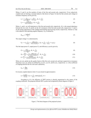
between the transmitting and receiving sides, the power was switched to one loop of the inductors for power
transmission and power reception.
A WPT system of 13.56 MHz was introduced by [12] and investigated both theoretically and
experimentally in addition to simulation. A relative high improvement in efficiency of about 41.7% was
achieved. Three phase angles had been designed and analyzed in [13]. Single power amplifier on the primary
side and two power amplifiers were located at the secondary side. The proposed multi-degrees method of
phase control was capable of achieving simultaneously additional compensation of the reactance, output
regulation, and load transformation.
A consistent optimization technique was conducted by [14] for WPT systems equipped with passive
element’s enhancement beginning from simple reflectors, intermediate relays, and general electromagnetic
focusing and guiding structures, like metamaterials and metasurfaces. The proposed work efficiently solved
the problem of optimization using arbitrary numbers of passive elements.
The work conducted by [15] presented and explained the published techniques and principles
concerning all aspects of inductive link design processes such that no specific preceding information about
inductive link designs are required. The work in [16] introduced accurate formulas for calculating mutual
inductance between spiral coils using Gaussian integration method. The researches introduced by [17-22]
concern enhancing coupling coefficients in different environments of inductive links in addition to
applications of WPT technologies in contactless electrical vehicles and energizing medical sensors.
In this work, poor efficiency of conventional wireless powering process is enhanced by
strengthening the mutual coupling along with power transmission path and conditioning the receiving circuit
such that it accomplishes maximum power reception to load node.
2. Design of the proposed efficient WPT system
The inductive mutual coupling Mab between two 1-turn planar spiral coils is shown in Figure 1a. The
mutual inductance between these two coils is given by [7]
𝑀 ⁄ 1 𝛾 𝛾 (1)
𝛾 (2)
Where, a and b are the outer radii of the first and second coils, respectively. µ0 is the permeability of free
space and z is the distance between the centers of the two coils, which are aligned coaxially.
(a) (b)
Figure 1. Inductive link, (a) coupling between two 1-turn coils, (b) modeling of two coil inductive link.
For multi-turns planar spiral coils, (1) can be modified to
𝑀 ∑ ∑ ⁄ 1 𝛾 𝛾 (3)
𝛾 (4)](https://image.slidesharecdn.com/192045727novedilhamrepaired-210701060013/85/Design-and-implementation-of-an-efficient-WPT-system-2-320.jpg)
![Int J Pow Elec & Dri Syst ISSN: 2088-8694
Design and implementation of an efficient WPT system (Abdulkareem Mokif Obais)
715
The proposed WPT system depicted in Figure 2 can be schematically represented by the circuit
shown Figure 6. In this Figure, R1, R2, R3, R4, R5, R6, and R7 are the AC resistances of the coils L1, L2, L3, L4,
L5, L6, and L7, respectively. C1, C 2, C 3, C 4, and C 5 are tuning capacitors of transmitting, first resonator,
second resonator, third resonator, and receiving circuits, respectively. Each M represents the mutual
inductance between two certain coils. For example M12 represents the mutual inductance between L1 and L2.
M12 is equal to M21 (M12=M21) and this is applicable for each two coils.
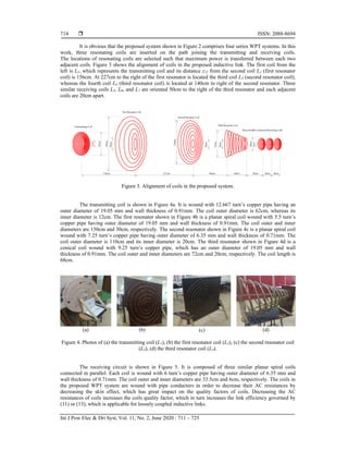
Figure 5. A photo of the receiving circuit, which is composed of three planar spiral coils (L5, L6, and L7).
Figure 6. Schematic representation of the proposed system.
The inductances of planar spiral coils can be calculated by [15]
𝐿 𝑙𝑛
.
0.2𝛽 (14)
Where, the average diameter is denoted by davg = 0.5(do+di). di and d0 are the inner and outer diameters of
the coil, respectively, while β is the fill-factor, which is given by
𝛽 (15)
The inductance of the conical coil shown in Figure 7 can be calculated as follows [23]:
𝐿
.
, 𝜇𝐻 (16)
Where, n, di, s, and Y are coil number of turns, inner diameter, distance between two adjacent turns, and coil
angle, respectively. Y and s are defined by](https://image.slidesharecdn.com/192045727novedilhamrepaired-210701060013/85/Design-and-implementation-of-an-efficient-WPT-system-5-320.jpg)
![ ISSN: 2088-8694
Int J Pow Elec & Dri Syst, Vol. 11, No. 2, June 2020 : 711 – 725
716
𝑌 𝑡𝑎𝑛
.
(17)
𝑠 (18)
Where, d0 is the coil outer diameter. W and l are coil axial and longitudinal lengths, respectively. All
dimensions are in inches. Substituting for n=9.25, di=20cm=7.874 inches, d0=72cm=28.346 inches,
l=68cm=26.772 inches, and W=72.8cm=28.661 inches into (16) to (18) gives Lcon=22 µH.
Figure 7. The inverse conical coil.
The DC resistances of all coils in the proposed WPT system can be calculated by
𝑅 (19)
Where, lC, σCu, w, and wth, are the coil length, conductivity of copper, outer diameter of coil pipe conductor,
and wall thickness of the pipe. The calculated inductances and DC resistances are listed in Table 1. The
mutual inductances between coils can be calculated using (3). The coefficients of coupling between coils are
calculated according to (12). The calculated mutual inductances and their corresponding coefficients of
coupling are listed in Table 2.
Table 1. Coil’s calculated DC resistance and inductances
Coil Name DC Resistance (Ω) Inductance (µH)
L1 0.0041827 46.334
L2 0.00448 23.864
L3 0.018474 29.3
L4 0.0039 22
L5, L6, L7 0.00458 6.0745
The AC resistance RAC of a coil wound with copper conductors can be calculated by [24]
𝑅 𝑅 (20)
𝛿 (21)
Where, RDC, σCu, w, and δCu are the DC resistance of the coil, conductivity of copper, outer diameter of the
coil conductor, and copper skin depth at f0. Respectively.
Applying (20) using the conductor outer diameters and calculated DC resistance in Table 1, the AC
resistances of all coils are calculated and listed in Table 3.
W
Y
o
d
di
l](https://image.slidesharecdn.com/192045727novedilhamrepaired-210701060013/85/Design-and-implementation-of-an-efficient-WPT-system-6-320.jpg)
![Int J Pow Elec & Dri Syst ISSN: 2088-8694
Design and implementation of an efficient WPT system (Abdulkareem Mokif Obais)
717
Table 2. Mutual inductances and their corresponding coupling
coefficients
Mutual
Inductance
Value (µH)
Coefficient of
Coupling
Value
M12 0.2621 k12 0.007882
M13 0.0161 k13 0.000437
M14 0.003 k14 0.000094
M15 0.000281 k15 0.00001675
M16 0.0002564 k16 0.0000154
M17 0.0002345 k17 0.00001295
M23 0.1592 k23 0.006
M24 0.0179 k24 0.000781
M25 0.0015 k25 0.0001246
M26 0.0013 k26 0.000108
M27 0.0012 k27 0.0001
M34 0.1358 k34 0.00535
M35 0.007 k35 0.000528
M36 0.0057 k36 0.000427
M37 0.0046 k37 0.0003448
M45 0.1931 k45 0.0167
M46 0.0985 k46 0.00852
M47 0.0558 k47 0.004827
M56 0.5018 k56 0.083633
M57 0.1161 k57 0.01935
M67 0.5018 k67 0.083633
Table 3. Coil’s calculated AC resistances
Coil
Name
AC
Resistance
AC Resistance
Value (Ω)
L1 R1 0.185
L2 R2 0.2
L3 R3 0.27246
L4 R4 0.172
L5 R5 0.0676
L6 R6 0.0676
L7 R7 0.0676
Since the transmitting coil (L1) and the three resonating coils (L2, L3, and L4) are operating within
loosely coupled conditions, then the tuning capacitors C2, C3, and C4 shown in Figure 6 can be determined as
9.25nF, 7.5345nF, and 10.034463nF, respectively.The circuit elements C1 and L1 in Figure 6 are parts of the
output circuit of the class-E power amplifier, which represents the power transmitter of the proposed efficient
WPT system. The series combination formed by C1 and L1 Are designed to resonate at a frequency slightly
less than f0 and their equivalent impedance at the resonance frequency f0 is R1+jX, where X is defined by [25]
𝑋 1.152𝑅 𝜔 𝐿 (22)
Where, R represents the resistive load of class-E power amplifier and can be determined by
𝑅 𝑅 𝑅 (23)
The tuning capacitor C5 of the receiving coils shown in Figure 6 can be approximately determined in
a different procedure. Figure 8 models the receiving coils without C5 and RL. Since the receiving circuit is
symmetrical around the branch including L6, then I5=I7 and I6=-2I5. Consequently, the impedance ZRCV of the
parallel-connected receiving coils can be determined by
𝑍 0.5𝑅 𝑗0.5𝜔 𝐿 𝑗𝜔 𝑀 𝑗0.5𝜔 𝑀 // 𝑅 𝑗𝜔 𝐿 𝑗2𝜔 𝑀 (24)
Substituting the calculated circuit parameters in (24) gives
𝑍 0.023 𝑗4.04, 𝛺 (25)
Figure 8. Modeling of the receiving coils without C5 and RL.](https://image.slidesharecdn.com/192045727novedilhamrepaired-210701060013/85/Design-and-implementation-of-an-efficient-WPT-system-7-320.jpg)
![ ISSN: 2088-8694
Int J Pow Elec & Dri Syst, Vol. 11, No. 2, June 2020 : 711 – 725
718
According to (25), the required value for C5 to accomplish resonance is 116.3nF. At resonance
frequency f0 and after tuning all capacitors such that all link circuits resonate at the same time, the link currents can be
related to each other by
⎣
⎢
⎢
⎢
⎢
⎢
⎡
𝑉
0
0
0
0
0
0⎦
⎥
⎥
⎥
⎥
⎥
⎤
⎣
⎢
⎢
⎢
⎢
⎢
⎡
𝑅 𝑗𝑋
𝑗𝜔 𝑀
𝑗𝜔 𝑀
𝑗𝜔 𝑀
𝑗𝜔 𝑀
𝑗𝜔 𝑀
𝑗𝜔 𝑀
𝑗𝜔 𝑀
𝑅
𝑗𝜔 𝑀
𝑗𝜔 𝑀
𝑗𝜔 𝑀
𝑗𝜔 𝑀
𝑗𝜔 𝑀
𝑗𝜔 𝑀
𝑗𝜔 𝑀
𝑅
𝑗𝜔 𝑀
𝑗𝜔 𝑀
𝑗𝜔 𝑀
𝑗𝜔 𝑀
𝑗𝜔 𝑀
𝑗𝜔 𝑀
𝑗𝜔 𝑀
𝑅
𝑗𝜔 𝑀
𝑗𝜔 𝑀
𝑗𝜔 𝑀
𝑗𝜔 𝑀
𝑗𝜔 𝑀
𝑗𝜔 𝑀
𝑗𝜔 𝑀
𝑍
𝑍
𝑍
𝑗𝜔 𝑀
𝑗𝜔 𝑀
𝑗𝜔 𝑀
𝑗𝜔 𝑀
𝑍
𝑍
𝑍
𝑗𝜔 𝑀
𝑗𝜔 𝑀
𝑗𝜔 𝑀
𝑗𝜔 𝑀
𝑍
𝑍
𝑍 ⎦
⎥
⎥
⎥
⎥
⎥
⎤
⎣
⎢
⎢
⎢
⎢
⎢
⎡
𝐼
𝐼
𝐼
𝐼
𝐼
𝐼
𝐼 ⎦
⎥
⎥
⎥
⎥
⎥
⎤
(26)
Where, I1, I 2, I 3, I 4, I 5, I 6, and I 7 are the currents flowing through coils L1, L2, L3, L4, L5, L6, and L7, respectively.
Since, L1 and C1 are parts of the class-E driving power amplifier and resonate at a frequency slightly less than the link
resonance frequency f0, the inductive reactance X represents their equivalent reactance at f0. Z55, Z56, Z57, Z65, Z66, Z67,
Z75, Z76, and Z77 are defined by
𝑍 𝑍 𝑍
𝑍 𝑍 𝑍
𝑍 𝑍 𝑍
⎣
⎢
⎢
⎢
⎡𝑅 𝑗𝜔 𝐿 𝑗𝜔 𝑀 𝑗𝜔 𝑀
𝑀 𝑅 𝑗𝜔 𝐿 𝑀
𝑀 𝑀 𝑅 𝑗𝜔 𝐿 ⎦
⎥
⎥
⎥
⎤
(27)
According to the block diagram of the overall proposed WPT system, there are four series WPT
systems namely WPT1, WPT2, WPT3, and WPT4. The first three systems WPT1, WPT2, and WPT3 are
loosely coupled systems due to the relatively large distances between their transmitting and receiving coils,
thus the first WPT system (WPT1) can be analyzed separately from other systems. Figure 9 shows the model
of the resonant inductive link corresponding to WPT1 system. At resonance frequency f0, the reflected
resistance Rrefl from the secondary side (first, second, and third resonators) in the primary side (transmitting
coil) is determined according to Equation (7) as 1.56Ω. V´ in Figure 9 represents the voltage across the
resistive load of class-E power amplifier. According to [25], V´ has an amplitude of Vom and phase of φ=-
32.40
. The maximum possible value of Vom is 1.074VDD=1.074×12V=12.888V, thus the voltage Vi can be
determined by
𝑉 𝑅 𝑅 𝑗𝑋 𝐼 1.7463 𝑗2 𝐼 (28)
Substituting all calculated mutual inductances, coil’s self-inductances, coil’s AC resistances, X, and
C5 into (26) and (27) gives
⎣
⎢
⎢
⎢
⎢
⎢
⎡
𝑉
0
0
0
0
0
0⎦
⎥
⎥
⎥
⎥
⎥
⎤
⎣
⎢
⎢
⎢
⎢
⎢
⎡
0.185 𝑗2
𝑗0.558
𝑗0.034
𝑗0.0064
𝑗0.0006
𝑗0.00055
𝑗0.0005
𝑗0.558
0.2
𝑗0.3388
𝑗0.0381
𝑗0.0032
𝑗0.0028
𝑗0.0026
𝑗0.034
𝑗0.3388
0.27246
𝑗0.289
𝑗0.0149
𝑗0.0121
𝑗0.0098
𝑗0.0064
𝑗0.0381
𝑗0.289
0.172
𝑗0.411
𝑗0.21
𝑗0.1188
𝑗0.0006
𝑗0.0032
𝑗0.0149
𝑗0.411
0.07 𝑗8.9
𝑗2.972
𝑗3.793
𝑗0.00055
𝑗0.0028
𝑗0.0121
𝑗0.21
𝑗2.972
0.07 𝑗8.9
𝑗2.972
𝑗0.0005
𝑗0.0026
𝑗0.0098
𝑗0.1188
𝑗3.793
𝑗2.972
0.07 𝑗8.9⎦
⎥
⎥
⎥
⎥
⎥
⎤
⎣
⎢
⎢
⎢
⎢
⎢
⎡
𝐼
𝐼
𝐼
𝐼
𝐼
𝐼
𝐼 ⎦
⎥
⎥
⎥
⎥
⎥
⎤
(29)
Figure 9. Modeling of the first WPT system (WPT1).](https://image.slidesharecdn.com/192045727novedilhamrepaired-210701060013/85/Design-and-implementation-of-an-efficient-WPT-system-8-320.jpg)
![Int J Pow Elec & Dri Syst ISSN: 2088-8694
Design and implementation of an efficient WPT system (Abdulkareem Mokif Obais)
719
Substituting (28) into (29) and determining the inverse of the resulted matrix produce 𝐼
0.136 𝑗1.61 𝐼 , 𝐼 0.8 𝑗0.341 𝐼 , 𝐼 0.306 𝑗1.184 𝐼 , 𝐼 0.039 𝑗0.13 𝐼 , 𝐼
0.031 𝑗0.101 𝐼 , and 𝐼 0.033 𝑗0.101 𝐼 .
The output voltage V0, input power Pi, output power P0, and overall link efficiency ηoverall are
determined by
𝑉 𝐼 𝐼 𝐼 1.462 𝑗0.404 𝐼 (30)
𝑃 𝐼 𝑅 𝑅 1.7463𝐼 (31)
𝑃
| . . | .
(32)
𝜂 % 100%
.
100% (33)
The above overall link efficiency corresponds to wirelessly energizing a load circuit located at
6.61m from the power source taking into account strengthening the inductive coupling environment and
conditioning the power receiving circuit for maximum power reception. If only one receiving coil is used and
located at the same distance from the power source without using resonators for strengthening the inductive
coupling, then according to (13), the efficiency for single coil receiving circuit without using resonators is
calculated at RL=130Ω as follows:
𝜂 % 100% 0.00421% (34)
The overall link efficiency of the proposed system at a load of 130Ω is calculated as
𝜂
.
100%
.
100% 1.0154% (35)
To show the significance of the efficiency enhancement processed in this work, what is known as
the efficiency gain Geff adopted here reflects this as follows:
𝐺
.
.
241.184 (36)
Many techniques are exploited in the design of the WPT transmitter to target relatively remote
electrical nodes required to be wirelessly energized. The most efficient technique is class-E power amplifier,
which is a switch mode power amplifier characterized by high efficiency and high power. Therefore such
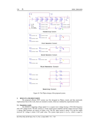
kind of power amplifiers are recommended to be adopted in the design of WPT systems. Figure 10 shows the
PSpice design of the proposed efficient WPT system.
The class-E power amplifier in the proposed system is loaded by an RLC combination composed of
a series RLC circuit represented by C1, L1, and R1 shunted by a capacitor CSH. L1 and R1 represent the
inductance and AC resistance of the transmitting coil, respectively. C1 is a tuning capacitor resonates with L1
at a frequency slightly less than f0, whereas CSH resonates with the series RLC (C1, L1, and R1) circuit at f0.
Using (22) at an operating frequency of 338.6 kHz, C1 is calculated as 4.8631nF. CSH is determined by [25]
𝐶
.
52.1 𝑛𝐹 (37)](https://image.slidesharecdn.com/192045727novedilhamrepaired-210701060013/85/Design-and-implementation-of-an-efficient-WPT-system-9-320.jpg)
![ ISSN: 2088-8694
Int J Pow Elec & Dri Syst, Vol. 11, No. 2, June 2020 : 711 – 725
724
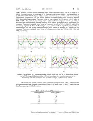
The effects of resonators on received AC power are addressed in this work. Table 5 lists the
received AC power and efficiency for all important cases of removing resonators from the circuit of the
practical WPT system taking into account a DC input power of 22.8W, which is taken as reference power
during the calculation of efficiency.
Table 5. Efficiency gain values of different WPT systems
System Type Received AC Power (mW) Efficiency %
Overall WPT System 32.768 0.144
Overall WPT System without First resonator 1 0.02
Overall WPT System without Second resonator 3.53 0.075625
Overall WPT System without Third resonator 1.25 0.003
Overall WPT system without second & third resonators 0.2 74.6×10⁻⁵
Overall WPT System without resonators 0.0026 3×10⁻⁵
4. CONCLUSION
In this work, an adaptive efficient WPT system is introduced. This system is carried out on PSpice
and validated experimentally. Both simulative and experimental WPT system have accomplished significant
enhancement in efficiency. The proposed WPT systems has three resonators and three parallel connected
identical receiving coils located at 6.61m from the power transmitter. The efficiency enhancement
approaches thousands times the efficiency of a conventional WPT system having similar power transmitter
located at the same distance from the receiving circuit, which has a single coil identical to those in the
proposed efficient WPT system. The conclusions of this work are summarized in: Both simulative and
practical systems have demonstrated that efficiency enhancement can be accomplished through inserting
resonators along with energy transmission path. Both simulative and practical systems have demonstrated
that efficiency enhancement can be accomplished through the modification of the receiving circuit using
parallel connected receiving coils. More power can be received when the reactance of the equivalent
receiving coil is much less than the load impedance. Energy transmission can approach distant nodes via
inserting more resonators along the path toward the targeted node. Heavier power transmission requires
lower frequency range, but bigger sending and receiving antennas.
Both systems show similar responses, which they differ in amounts, but exhibit similar behaviors.
The differences in amounts are due to commercial tuning capacitors which have dielectric resistances
responsible for causing significant reduction in the resonant currents in all resonator circuits.
REFERENCES
[1] A. Esser and H.-C. Skudelny, “A new approach to power supplies for robots,” IEEE Transactions on Industry
Applications, vol. 27, no. 5, pp. 872–875, 1991.
[2] L. Cannon, J. F. Hoburg, D. D. Stancil, S. C. Goldstein, “Magnetic resonant coupling as a potential means for
wireless power transfer to multiple small receivers,” IEEE Transactions on Power Electronics, vol. 24, no. 7, pp.
1819-1825, 2009.
[3] J. J. Casanova, Z. N. Low, and J. Lin, “Design and optimization of a Class-E amplifier for a loosely coupled planar
wireless power system,” IEEE Transactions on Circuits and Systems-II: Express Briefs, vol. 56, no. 11, pp. 830–
834, 2009.
[4] J. A. Taylor, Z. N. Low, J. Casanova, and J. Lin, “A wireless power station for laptop computers Jason,” IEEE
Radio and Wireless Symposium (RWS), 10-14 Jan. 2010, New Orleans, LA, USA,
pp. 625-628, 2010.
[5] M. Pinuela, D. C. Yates, S. Lucyszyn, and P. D. Mitcheson, “Maximizing DC to load efficiency for inductive
power transfer,” IEEE Transactions on Power Electronics, vol. 50, no. 6, pp. 1-11, 2010.
[6] A. Massa, G. Oliveri , F. Viani , and P. Rocca, “Array designs for long-distance wireless power transmission: State-
of-the-art and innovative solutions,” Proceedings of the IEEE, vol.101, no. 6,
pp. 1464- 1481 , 2013.
[7] S. Raju, R. Wu, M. Chan, and C. P.Yue, “Modeling of mutual coupling between planar inductors
in wireless power applications,” IEEE Transactions On Power Electronics, vol. 29, no. 1,
pp. 481-490, 2014.
[8] Y. Cheng and Y. Shu, “A new analytical calculation of the mutual inductance of the coaxial spiral rectangular
coils,” IEEE Transactions on Magnetics, vol. 50, no. 4, pp. 1-6, 2014.
[9] J. Kim, -J. Park, “Approximate closed-form formula for calculating ohmic resistance in coils of parallel round wires
with unequal pitches,” IEEE Transactions On Industrial Electronics, vol. 62, no. 6,
pp. 3482-3489, 2015.](https://image.slidesharecdn.com/192045727novedilhamrepaired-210701060013/85/Design-and-implementation-of-an-efficient-WPT-system-14-320.jpg)
![Int J Pow Elec & Dri Syst ISSN: 2088-8694
Design and implementation of an efficient WPT system (Abdulkareem Mokif Obais)
725
[10] L. Tan, J. Li, C. Chen, C. Yan, J. Guo, and X. Huang, “Analysis and performance improvement of
wpt systems in the environment of single non-ferromagnetic metal plates,” Energies, vol 9,
pp. 1-16, 2016.
[11] V. V. Nair and J. R. Choi, “An efficiency enhancement technique for a wireless power transmission system based
on a multiple coil switching technique,” Energies vol. 9, pp. 1-15, 2016.
[12] J. Chen, Z. Ding, Z. Hu, Sh. Wang, Y. Cheng, M. Liu, B. Wei, and S. Wang, “Metamaterial-based high-efficiency
wireless power transfer system at 13.56 Mhz for low power applications,” Progress in Electromagnetics Research,
vol.72, pp.17-30, 2017.
[13] X. Liu, T. Wang, X. Yang, N. Jin, and H. Tang, “Analysis and design of a wireless power transfer system with dual
active bridges,” Energies vol. 10, pp. 1-20, 2017.
[14] H.-D. Lang and C. D. Sarris, “Optimization of wireless power transfer systems enhanced by passive elements and
metasurfaces,” IEEE Transactions on Antennas and Propagation, vol. 6, no. 10,
pp. 5462- 5474, 2017.
[15] M. Schormans, V. Valente, and A. Demosthenous, “Practical inductive link design for biomedical wireless power
transfer: A tutorial,” IEEE Transactions on Biomedical Circuits and Systems, vol. 12, no. 5, pp. 1112 - 1130, 2018.
[16] S. Liu, J. Su, and J, Lai, “Accurate expressions of mutual inductance and their calculation of archimedean spiral
coils,” Energies vol 12, 2017.
[17] A. Kurs, “Power transfer through strongly coupled resonances,” Master Thesis, Massachusetts Institute of
Technology, Massachusetts Ave, Cambridge, USA 2008.
[18] T. Peng, S. Koulouridis, and J. L. Volakis, “Miniaturization of conical helical antenna via optimized coiling,” Aces
Journal, vol. 26, no. 6, pp. 452-458, 2011.
[19] W. Junhua, “Resonant coupling energy transmission technology and its applications to implanted medical devices,”
PhD Thesis, The Hong Kong Polytechnic University, Hong Kong, 2012.
[20] M. C. Pickelsimer, “Wireless power transfer system for electric vehicles with power factor correction,” MSc
Thesis, University of Tennessee, Knoxville, Tennessee, 2012.
[21] A. Bourřa and M. Husák, “Communication and powering scheme for wireless and battery-less measurement,”
Radioengineering, vol. 21, no. 1, pp. 239-245, 2012.
[22] T. Sun, X. Xie, and Z. Wang, "Wireless power transfer for medical microsystems", Springer, New York, USA,
2013.
[23] E. B. Wasatonic, “Comparison of tesla coil driver topologies: Rotary spark gap versus double resonant solid state,”
MSc Thesis, The Pennsylvania State University, Pennsylvania, USA, 2013.
[24] R. Ludwig and P. Bretchko, “RF circuit design: Theory & applications,” Prentice Hall, Upper Saddle River, New
Jersey, USA, 2000.
[25] J. Rogers and C. Plett, “Radio frequency integrated circuit design,” Artech House, Boston, London, U.K, 2003.](https://image.slidesharecdn.com/192045727novedilhamrepaired-210701060013/85/Design-and-implementation-of-an-efficient-WPT-system-15-320.jpg)