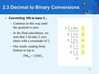
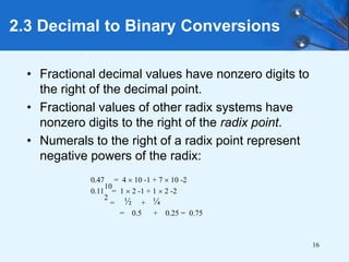
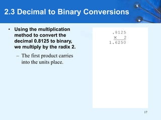
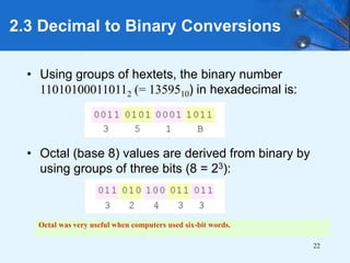
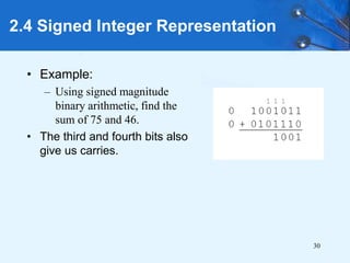
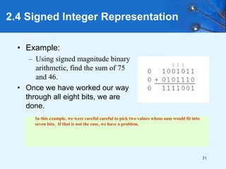
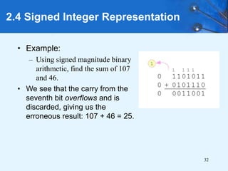
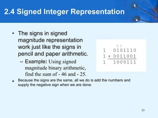
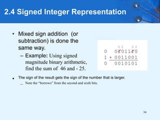
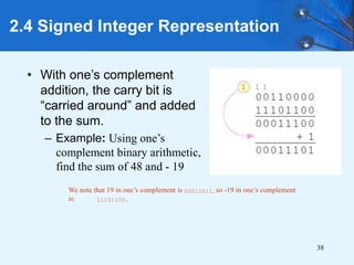
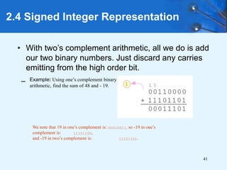
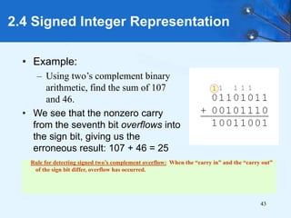
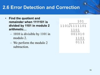
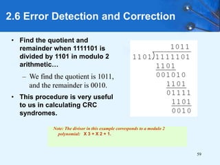
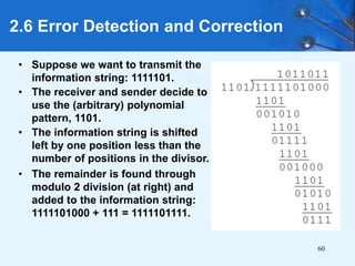
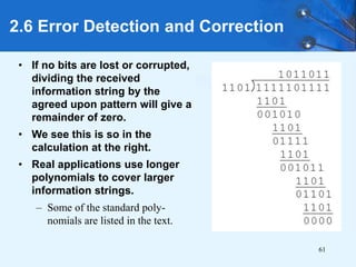
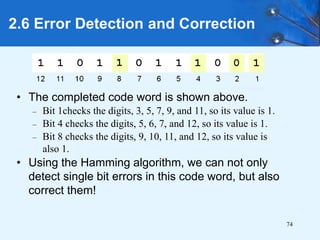
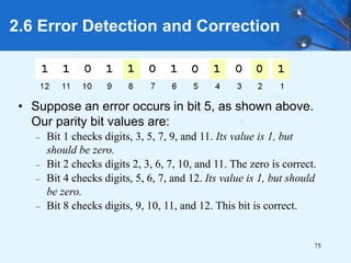
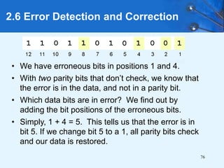
SlideShare a Scribd company logo
1 of 78
Chapter 2
Data Representation in
Computer Systems
2
Chapter 2 Objectives
• Understand the fundamentals of numerical data
representation and manipulation in digital
computers.
• Master the skill of converting between various
radix systems.
• Understand how errors can occur in computations
because of overflow and truncation.
3
Chapter 2 Objectives
• Gain familiarity with the most popular character
codes.
• Understand the concepts of error detecting and
correcting codes.
4
2.1 Introduction
• A bit is the most basic unit of information in a
computer.
– It is a state of “on” or “off” in a digital circuit.
– Sometimes these states are “high” or “low” voltage
instead of “on” or “off..”
• A byte is a group of eight bits.
– A byte is the smallest possible addressable unit of
computer storage.
– The term, “addressable,” means that a particular byte can
be retrieved according to its location in memory.
5
2.1 Introduction
• A word is a contiguous group of bytes.
– Words can be any number of bits or bytes.
– Word sizes of 16, 32, or 64 bits are most common.
– In a word-addressable system, a word is the smallest
addressable unit of storage.
• A group of four bits is called a nibble (or nybble).
– Bytes, therefore, consist of two nibbles: a “high-order
nibble,” and a “low-order” nibble.
6
2.2 Positional Numbering Systems
• Bytes store numbers using the position of each bit
to represent a power of 2.
– The binary system is also called the base-2 system.
– Our decimal system is the base-10 system. It uses
powers of 10 for each position in a number.
– Any integer quantity can be represented exactly using any
base (or radix).
7
2.2 Positional Numbering Systems
• The decimal number 947 in powers of 10 is:
• The decimal number 5836.47 in powers of 10 is:
5  10 3 + 8  10 2 + 3  10 1 + 6  10 0
+ 4  10 -1 + 7  10 -2
9  10 2 + 4  10 1 + 7  10 0
8
2.2 Positional Numbering Systems
• The binary number 11001 in powers of 2 is:
• When the radix of a number is something other
than 10, the base is denoted by a subscript.
– Sometimes, the subscript 10 is added for emphasis:
110012 = 2510
1  2 4 + 1  2 3 + 0  2 2 + 0  2 1 + 1  2 0
= 16 + 8 + 0 + 0 + 1 = 25
9
2.3 Decimal to Binary Conversions
• Because binary numbers are the basis for all data
representation in digital computer systems, it is
important that you become proficient with this radix
system.
• Your knowledge of the binary numbering system
will enable you to understand the operation of all
computer components as well as the design of
instruction set architectures.
10
2.3 Decimal to Binary Conversions
• In an earlier slide, we said that every integer value
can be represented exactly using any radix
system.
• You can use either of two methods for radix
conversion: the subtraction method and the
division remainder method.
• The subtraction method is more intuitive, but
cumbersome. It does, however reinforce the ideas
behind radix mathematics.
11
2.3 Decimal to Binary Conversions
• Method of converting integers from decimal to
some other radix uses division.
• This method is mechanical and easy.
• It employs the idea that successive division by a
base is equivalent to successive subtraction by
powers of the base.
• Let’s use the division remainder method to
convert 190 in decimal to base 3.
12
• Converting 190 to base 3...
– First we take the number
that we wish to convert and
divide it by the radix in
which we want to express
our result.
– In this case, 3 divides 190
63 times, with a remainder
of 1.
– Record the quotient and the
remainder.
2.3 Decimal to Binary Conversions
13
• Converting 190 to base 3...
– 63 is evenly divisible by 3.
– Our remainder is zero, and
the quotient is 21.
2.3 Decimal to Binary Conversions
14
• Converting 190 to base 3...
– Continue in this way until
the quotient is zero.
– In the final calculation, we
note that 3 divides 2 zero
times with a remainder of 2.
– Our result, reading from
bottom to top is:
19010 = 210013
2.3 Decimal to Binary Conversions
15
2.3 Decimal to Binary Conversions
• Fractional values can be approximated in all
base systems.
• Unlike integer values, fractions do not
necessarily have exact representations under all
radices.
• The quantity ½ is exactly representable in the
binary and decimal systems, but is not in the
ternary (base 3) numbering system.
16
2.3 Decimal to Binary Conversions
• Fractional decimal values have nonzero digits to
the right of the decimal point.
• Fractional values of other radix systems have
nonzero digits to the right of the radix point.
• Numerals to the right of a radix point represent
negative powers of the radix:
0.47
10
= 4  10 -1 + 7  10 -2
0.11
2
= 1  2 -1 + 1  2 -2
= ½ + ¼
= 0.5 + 0.25 = 0.75
17
• Using the multiplication
method to convert the
decimal 0.8125 to binary,
we multiply by the radix 2.
– The first product carries
into the units place.
2.3 Decimal to Binary Conversions
18
• Converting 0.8125 to binary . . .
– Ignoring the value in the units
place at each step, continue
multiplying each fractional
part by the radix.
2.3 Decimal to Binary Conversions
19
• Converting 0.8125 to binary . . .
– You are finished when the
product is zero, or until you
have reached the desired
number of binary places.
– Our result, reading from top to
bottom is:
0.812510 = 0.11012
– This method also works with
any base. Just use the target
radix as the multiplier.
2.3 Decimal to Binary Conversions
20
2.3 Decimal to Binary Conversions
• The binary numbering system is the most
important radix system for digital computers.
• However, it is difficult to read long strings of binary
numbers-- and even a modestly-sized decimal
number becomes a very long binary number.
– For example: 110101000110112 = 1359510
• For compactness and ease of reading, binary
values are usually expressed using the
hexadecimal, or base-16, numbering system.
21
2.3 Decimal to Binary Conversions
• The hexadecimal numbering system uses the
numerals 0 through 9 and the letters A through F.
– The decimal number 12 is C16.
– The decimal number 26 is 1A16.
• It is easy to convert between base 16 and base 2,
because 16 = 24.
• Thus, to convert from binary to hexadecimal, all
we need to do is group the binary digits into
groups of four.
A group of four binary digits is called a hextet
22
2.3 Decimal to Binary Conversions
• Using groups of hextets, the binary number
110101000110112 (= 1359510) in hexadecimal is:
• Octal (base 8) values are derived from binary by
using groups of three bits (8 = 23):
Octal was very useful when computers used six-bit words.
23
2.4 Signed Integer Representation
• The conversions we have so far presented have
involved only positive numbers.
• To represent negative values, computer systems
allocate the high-order bit to indicate the sign of a
value.
– The high-order bit is the leftmost bit in a byte. It is also
called the most significant bit.
• The remaining bits contain the value of the
number.
24
2.4 Signed Integer Representation
• There are three ways in which signed binary
numbers may be expressed:
– Signed magnitude,
– One’s complement and
– Two’s complement.
• In an 8-bit word, signed magnitude
representation places the absolute value of
the number in the 7 bits to the right of the
sign bit.
25
2.4 Signed Integer Representation
• For example, in 8-bit signed magnitude,
positive 3 is: 00000011
• Negative 3 is: 10000011
• Computers perform arithmetic operations on
signed magnitude numbers in much the same
way as humans carry out pencil and paper
arithmetic.
– Humans often ignore the signs of the operands
while performing a calculation, applying the
appropriate sign after the calculation is complete.
26
2.4 Signed Integer Representation
• Binary addition is as easy as it gets. You need
to know only four rules:
0 + 0 = 0 0 + 1 = 1
1 + 0 = 1 1 + 1 = 10
• The simplicity of this system makes it possible
for digital circuits to carry out arithmetic
operations.
Let’s see how the addition rules work with signed magnitude numbers . . .
27
2.4 Signed Integer Representation
• Example:
– Using signed magnitude
binary arithmetic, find the
sum of 75 and 46.
• First, convert 75 and 46 to
binary, and arrange as a sum,
but separate the (positive)
sign bits from the magnitude
bits.
28
2.4 Signed Integer Representation
• Example:
– Using signed magnitude
binary arithmetic, find the
sum of 75 and 46.
• Just as in decimal arithmetic,
we find the sum starting with
the rightmost bit and work left.
29
2.4 Signed Integer Representation
• Example:
– Using signed magnitude
binary arithmetic, find the
sum of 75 and 46.
• In the second bit, we have a
carry, so we note it above the
third bit.
30
2.4 Signed Integer Representation
• Example:
– Using signed magnitude
binary arithmetic, find the
sum of 75 and 46.
• The third and fourth bits also
give us carries.
31
2.4 Signed Integer Representation
• Example:
– Using signed magnitude binary
arithmetic, find the sum of 75
and 46.
• Once we have worked our way
through all eight bits, we are
done.
In this example, we were careful careful to pick two values whose sum would fit into
seven bits. If that is not the case, we have a problem.
32
2.4 Signed Integer Representation
• Example:
– Using signed magnitude binary
arithmetic, find the sum of 107
and 46.
• We see that the carry from the
seventh bit overflows and is
discarded, giving us the
erroneous result: 107 + 46 = 25.
33
2.4 Signed Integer Representation
• The signs in signed
magnitude representation
work just like the signs in
pencil and paper arithmetic.
– Example: Using signed
magnitude binary arithmetic,
find the sum of - 46 and - 25.
• Because the signs are the same, all we do is add the numbers and
supply the negative sign when we are done.
34
2.4 Signed Integer Representation
• Mixed sign addition (or
subtraction) is done the
same way.
– Example: Using signed
magnitude binary arithmetic,
find the sum of 46 and - 25.
• The sign of the result gets the sign of the number that is larger.
– Note the “borrows” from the second and sixth bits.
35
2.4 Signed Integer Representation
• Signed magnitude representation is easy for
people to understand, but it requires
complicated computer hardware.
• Another disadvantage of signed magnitude is
that it allows two different representations for
zero: positive zero and negative zero.
• For these reasons (among others) computers
systems employ complement systems for
numeric value representation.
36
2.4 Signed Integer Representation
• In complement systems, negative values are
represented by some difference between a
number and its base.
• In diminished radix complement systems, a
negative value is given by the difference between
the absolute value of a number and one less than
its base.
• In the binary system, this gives us one’s
complement. It amounts to little more than flipping
the bits of a binary number.
37
2.4 Signed Integer Representation
• For example, in 8-bit one’s complement,
positive 3 is:00000011
• Negative 3 is: 11111100
• In one’s complement, as with signed
magnitude, negative values are indicated by a
1 in the high order bit.
• Complement systems are useful because they
eliminate the need for subtraction. The
difference of two values is found by adding the
minuend to the complement of the subtrahend.
38
2.4 Signed Integer Representation
• With one’s complement
addition, the carry bit is
“carried around” and added
to the sum.
– Example: Using one’s
complement binary arithmetic,
find the sum of 48 and - 19
We note that 19 in one’s complement is 00010011, so -19 in one’s complement
is: 11101100.
39
2.4 Signed Integer Representation
• Although the “end carry around” adds some
complexity, one’s complement is simpler to
implement than signed magnitude.
• But it still has the disadvantage of having two
different representations for zero: positive
zero and negative zero.
• Two’s complement solves this problem.
• Two’s complement is the radix complement of
the binary numbering system.
40
2.4 Signed Integer Representation
• To express a value in two’s complement:
– If the number is positive, just convert it to binary and
you’re done.
– If the number is negative, find the one’s complement of
the number and then add 1.
• Example:
– In 8-bit one’s complement, positive 3 is: 00000011
– Negative 3 in one’s complement is: 11111100
– Adding 1 gives us -3 in two’s complement form: 11111101.
41
2.4 Signed Integer Representation
• With two’s complement arithmetic, all we do is add
our two binary numbers. Just discard any carries
emitting from the high order bit.
We note that 19 in one’s complement is: 00010011, so -19 in one’s
complement is: 11101100,
and -19 in two’s complement is: 11101101.
– Example: Using one’s complement binary
arithmetic, find the sum of 48 and - 19.
42
2.4 Signed Integer Representation
• When we use any finite number of bits to
represent a number, we always run the risk of
the result of our calculations becoming too large
to be stored in the computer.
• While we can’t always prevent overflow, we can
always detect overflow.
• In complement arithmetic, an overflow condition
is easy to detect.
43
2.4 Signed Integer Representation
• Example:
– Using two’s complement binary
arithmetic, find the sum of 107
and 46.
• We see that the nonzero carry
from the seventh bit overflows into
the sign bit, giving us the
erroneous result: 107 + 46 = 25
Rule for detecting signed two’s complement overflow: When the “carry in” and the “carry out”
of the sign bit differ, overflow has occurred.
44
2.4 Signed Integer Representation
• Signed and unsigned numbers are both useful.
– For example, memory addresses are always unsigned.
• Using the same number of bits, unsigned integers
can express twice as many values as signed
numbers.
• Trouble arises if an unsigned value “wraps around.”
– In four bits: 1111 + 1 = 0000.
• Good programmers stay alert for this kind of
problem.
45
• Calculations aren’t useful until their results can
be displayed in a manner that is meaningful to
people.
• We also need to store the results of calculations,
and provide a means for data input.
• Thus, human-understandable characters must be
converted to computer-understandable bit
patterns using some sort of character encoding
scheme.
2.5 Character Codes
46
• As computers have evolved, character codes
have evolved.
• Larger computer memories and storage
devices permit richer character codes.
• The earliest computer coding systems used six
bits.
• Binary-coded decimal (BCD) was one of these
early codes. It was used by IBM mainframes in
the 1950s and 1960s.
2.5 Character Codes
47
• In 1964, BCD was extended to an 8-bit code,
Extended Binary-Coded Decimal Interchange
Code (EBCDIC).
• EBCDIC was one of the first widely-used
computer codes that supported upper and
lowercase alphabetic characters, in addition to
special characters, such as punctuation and
control characters.
• EBCDIC and BCD are still in use by IBM
mainframes today.
2.5 Character Codes
48
• Other computer manufacturers chose the 7-bit
ASCII (American Standard Code for Information
Interchange) as a replacement for 6-bit codes.
• While BCD and EBCDIC were based upon
punched card codes, ASCII was based upon
telecommunications (Telex) codes.
• Until recently, ASCII was the dominant
character code outside the IBM mainframe
world.
2.5 Character Codes
49
*Unicode
• Both EBCDIC and ASCII were built around the
Latin alphabet, they are restricted in their abilities
to provide data representation for the non-Latin
alphabets.
• Is a new international information exchange code.
• Because the base coding of Unicode is 16 bits, it
has the capacity to encode the majority of
characters used in every language of the world.
2.5 Character Codes
2.5 Character Codes
• Many of today’s systems embrace Unicode, a 16-
bit system that can encode the characters of
every language in the world.
– The Java programming language, and some operating
systems now use Unicode as their default character
code.
– The Unicode codespace consists of five parts,as shown
below in the table.
50
51
• The Unicode codes-
pace allocation is
shown at the right.
• The lowest-numbered
Unicode characters
comprise the ASCII
code.
• The highest provide
for user-defined
codes.
2.5 Character Codes
52
• It is physically impossible for any data recording or
transmission medium to be 100% perfect 100% of the time
over its entire expected useful life and also impossible to
detect or correct 100% of all errors that could occur in
a medium.
• As more bits are packed onto a square centimeter of disk
storage, as communications transmission speeds increase,
the likelihood of error increases.
• Thus, error detection and correction is critical to accurate
data transmission, storage and retrieval.
2.6 Error Detection and Correction
53
• Checksums are used in a wide variety of coding
systems, from bar codes to International Standard
Book Numbers (ISBNs).
• Checksums are self-checking codes that will quickly
indicate whether the preceding digits have been
misread.
• Longer data streams require more economical and
sophisticated error detection mechanisms.
• Check digits, appended to the end of a long number can
provide some protection against data input errors.
2.6 Error Detection and Correction
54
CRC (Cyclic redundancy check)
• Checksums and CRCs are examples of systematic
error detection.
• Cyclic redundancy checking (CRC) codes provide
error detection for large blocks of data.
• In systematic error detection a group of error control
bits is appended to the end of the block of
transmitted data.
– This group of bits is called a syndrome.
2.6 Error Detection and Correction
55
• Modulo 2 arithmetic works like clock arithmetic.
• In clock arithmetic, if we add 2 hours to 11:00, we
get 1:00.
• In modulo 2 arithmetic if we add 1 to 1, we get 0.
The addition rules couldn’t be simpler:
• CRCs are polynomials over the modulo 2
arithmetic field.
2.6 Error Detection and Correction
0 + 0 = 0 0 + 1 = 1
1 + 0 = 1 1 + 1 = 0
56
• Find the quotient and
remainder when 1111101 is
divided by 1101 in modulo 2
arithmetic.
– As with traditional division,
we note that the dividend is
divisible once by the divisor.
– We place the divisor under the
dividend and perform modulo
2 subtraction.
2.6 Error Detection and Correction
57
• Find the quotient and
remainder when 1111101 is
divided by 1101 in modulo 2
arithmetic…
– Now we bring down the next
bit of the dividend.
– We see that 00101 is not
divisible by 1101. So we place
a zero in the quotient.
2.6 Error Detection and Correction
58
• Find the quotient and
remainder when 1111101 is
divided by 1101 in modulo 2
arithmetic…
– 1010 is divisible by 1101 in
modulo 2.
– We perform the modulo 2
subtraction.
2.6 Error Detection and Correction
59
• Find the quotient and
remainder when 1111101 is
divided by 1101 in modulo 2
arithmetic…
– We find the quotient is 1011,
and the remainder is 0010.
• This procedure is very useful
to us in calculating CRC
syndromes.
2.6 Error Detection and Correction
Note: The divisor in this example corresponds to a modulo 2
polynomial: X 3 + X 2 + 1.
60
• Suppose we want to transmit the
information string: 1111101.
• The receiver and sender decide to
use the (arbitrary) polynomial
pattern, 1101.
• The information string is shifted
left by one position less than the
number of positions in the divisor.
• The remainder is found through
modulo 2 division (at right) and
added to the information string:
1111101000 + 111 = 1111101111.
2.6 Error Detection and Correction
61
• If no bits are lost or corrupted,
dividing the received
information string by the
agreed upon pattern will give a
remainder of zero.
• We see this is so in the
calculation at the right.
• Real applications use longer
polynomials to cover larger
information strings.
– Some of the standard poly-
nomials are listed in the text.
2.6 Error Detection and Correction
62
• Data transmission errors are easy to fix once an error
is detected.
– Just ask the sender to transmit the data again.
• In computer memory and data storage, however, this
cannot be done.
– Too often the only copy of something important is in
memory or on disk.
• Thus, to provide data integrity over the long term,
error correcting codes are required.
2.6 Error Detection and Correction
63
• Hamming codes and Reed-Soloman codes are two
important error correcting codes.
• Reed-Soloman codes are particularly useful in
correcting burst errors that occur when a series of
adjacent bits are damaged.
– Because CD-ROMs are easily scratched, they employ a type
of Reed-Soloman error correction.
• Because the mathematics of Hamming codes is
much simpler than Reed-Soloman, we discuss
Hamming codes in detail.
2.6 Error Detection and Correction
64
• Hamming codes are code words formed by adding
redundant check bits, or parity bits, to a data word.
• The Hamming distance between two code words is
the number of bits in which two code words differ.
• The minimum Hamming distance for a code is the
smallest Hamming distance between all pairs of
words in the code.
2.6 Error Detection and Correction
This pair of bytes has a Hamming
distance of 3:
65
• The minimum Hamming distance for a code,
D(min), determines its error detecting and error
correcting capability.
• For any code word, X, to be interpreted as a
different valid code word, Y, at least D(min)
single-bit errors must occur in X.
• Thus, to detect k (or fewer) single-bit errors, the
code must have a Hamming distance of
D(min) = k + 1.
2.6 Error Detection and Correction
66
• Hamming codes can detect D(min) - 1 errors
and correct errors
• Thus, a Hamming distance of 2k + 1 is
required to be able to correct k errors in any
data word.
• Hamming distance is provided by adding a
suitable number of parity bits to a data word.
2.6 Error Detection and Correction
67
• Suppose we have a set of n-bit code words
consisting of m data bits and r (redundant) parity
bits.
• An error could occur in any of the n bits, so each
code word can be associated with n erroneous
words at a Hamming distance of 1.
• Therefore,we have n + 1 bit patterns for each
code word: one valid code word, and n erroneous
words.
2.6 Error Detection and Correction
68
• With n-bit code words, we have 2 n possible code
words consisting of 2 m data bits (where n = m + r).
• This gives us the inequality:
(n + 1)  2 m  2 n
• Because n = m + r, we can rewrite the inequality
as:
(m + r + 1)  2 m  2 m + r or (m + r + 1)  2 r
– This inequality gives us a lower limit on the number of
check bits that we need in our code words.
2.6 Error Detection and Correction
69
• Suppose we have data words of length m = 4.
Then:
(4 + r + 1)  2 r
implies that r must be greater than or equal to 3.
• This means to build a code with 4-bit data words
that will correct single-bit errors, we must add 3
check bits.
• Finding the number of check bits is the hard part.
The rest is easy.
2.6 Error Detection and Correction
70
• Suppose we have data words of length m = 8.
Then:
(8 + r + 1)  2 r
implies that r must be greater than or equal to 4.
• This means to build a code with 8-bit data words
that will correct single-bit errors, we must add 4
check bits, creating code words of length 12.
• So how do we assign values to these check
bits?
2.6 Error Detection and Correction
71
• With code words of length 12, we observe that each
of the digits, 1 though 12, can be expressed in
powers of 2. Thus:
1 = 2 0 5 = 2 2 + 2 0 9 = 2 3 + 2 0
2 = 2 1 6 = 2 2 + 2 1 10 = 2 3 + 2 1
3 = 2 1 + 2 0 7 = 2 2 + 2 1 + 2 0 11 = 2 3 + 2 1 + 2 0
4 = 2 2 8 = 2 3 12 = 2 3 + 2 2
– 1 (= 20) contributes to all of the odd-numbered digits.
– 2 (= 21) contributes to the digits, 2, 3, 6, 7, 10, and 11.
– . . . And so forth . . .
• We can use this idea in the creation of our check bits.
2.6 Error Detection and Correction
72
• Using our code words of length 12, number each
bit position starting with 1 in the low-order bit.
• Each bit position corresponding to an even
power of 2 will be occupied by a check bit.
• These check bits contain the parity of each bit
position for which it participates in the sum.
2.6 Error Detection and Correction
73
• Since 2 (= 21) contributes to the digits, 2, 3, 6, 7, 10,
and 11. Position 2 will contain the parity for bits 3, 6,
7, 10, and 11.
• When we use even parity, this is the modulo 2 sum
of the participating bit values.
• For the bit values shown, we have a parity value of
0 in the second bit position.
2.6 Error Detection and Correction
What are the values for the other parity bits?
74
• The completed code word is shown above.
– Bit 1checks the digits, 3, 5, 7, 9, and 11, so its value is 1.
– Bit 4 checks the digits, 5, 6, 7, and 12, so its value is 1.
– Bit 8 checks the digits, 9, 10, 11, and 12, so its value is
also 1.
• Using the Hamming algorithm, we can not only
detect single bit errors in this code word, but also
correct them!
2.6 Error Detection and Correction
75
• Suppose an error occurs in bit 5, as shown above.
Our parity bit values are:
– Bit 1 checks digits, 3, 5, 7, 9, and 11. Its value is 1, but
should be zero.
– Bit 2 checks digits 2, 3, 6, 7, 10, and 11. The zero is correct.
– Bit 4 checks digits, 5, 6, 7, and 12. Its value is 1, but should
be zero.
– Bit 8 checks digits, 9, 10, 11, and 12. This bit is correct.
2.6 Error Detection and Correction
76
• We have erroneous bits in positions 1 and 4.
• With two parity bits that don’t check, we know that
the error is in the data, and not in a parity bit.
• Which data bits are in error? We find out by
adding the bit positions of the erroneous bits.
• Simply, 1 + 4 = 5. This tells us that the error is in
bit 5. If we change bit 5 to a 1, all parity bits check
and our data is restored.
2.6 Error Detection and Correction
77
• Computers store data in the form of bits, bytes,
and words using the binary numbering system.
• Hexadecimal numbers are formed using four-bit
groups called nibbles (or nibbles).
• Signed integers can be stored in one’s
complement, two’s complement, or signed
magnitude representation.
Chapter 2 Conclusion
78
• Character data is stored using ASCII, EBCDIC,
or Unicode.
• Error detecting and correcting codes are
necessary because we can expect no
transmission or storage medium to be perfect.
• CRC, Reed-Soloman, and Hamming codes are
three important error control codes.
Chapter 2 Conclusion

More Related Content

Similar to computer architecture organization in Ece

Data repersentation.
Data repersentation.Data repersentation.
Data repersentation.Ritesh Saini
 
Manoch1raw 160512091436
Manoch1raw 160512091436Manoch1raw 160512091436
Manoch1raw 160512091436marangburu42
 
Computer Oraganizaation.pptx
Computer Oraganizaation.pptxComputer Oraganizaation.pptx
Computer Oraganizaation.pptxbmangesh
 
Number-Systems presentation of the mathematics
Number-Systems presentation of the mathematicsNumber-Systems presentation of the mathematics
Number-Systems presentation of the mathematicsshivas379526
 
2s complement arithmetic
2s complement arithmetic2s complement arithmetic
2s complement arithmeticSanjay Saluth
 
Number Systems.ppt
Number Systems.pptNumber Systems.ppt
Number Systems.pptzorogoh2
 
EE5440 – Computer Architecture - Lecture 1
EE5440 – Computer Architecture - Lecture 1EE5440 – Computer Architecture - Lecture 1
EE5440 – Computer Architecture - Lecture 1Dilawar Khan
 
FYBSC IT Digital Electronics Unit I Chapter I Number System and Binary Arithm...
FYBSC IT Digital Electronics Unit I Chapter I Number System and Binary Arithm...FYBSC IT Digital Electronics Unit I Chapter I Number System and Binary Arithm...
FYBSC IT Digital Electronics Unit I Chapter I Number System and Binary Arithm...Arti Parab Academics
 
Chapter 1 number and code system sss
Chapter 1 number and code system sssChapter 1 number and code system sss
Chapter 1 number and code system sssBaia Salihin
 
digital-electronics lecture Ch 1and 2 -1.pptx
digital-electronics lecture Ch 1and 2 -1.pptxdigital-electronics lecture Ch 1and 2 -1.pptx
digital-electronics lecture Ch 1and 2 -1.pptxabelllll
 
Number system
Number systemNumber system
Number systemAmit Shaw
 
Binary computing
Binary computingBinary computing
Binary computingsamina khan
 

Similar to computer architecture organization in Ece (20)

Data repersentation.
Data repersentation.Data repersentation.
Data repersentation.
 
Manoch1raw 160512091436
Manoch1raw 160512091436Manoch1raw 160512091436
Manoch1raw 160512091436
 
Computer Oraganizaation.pptx
Computer Oraganizaation.pptxComputer Oraganizaation.pptx
Computer Oraganizaation.pptx
 
Number system
Number system Number system
Number system
 
Number-Systems presentation of the mathematics
Number-Systems presentation of the mathematicsNumber-Systems presentation of the mathematics
Number-Systems presentation of the mathematics
 
Lecture 2 ns
Lecture 2 nsLecture 2 ns
Lecture 2 ns
 
2s complement arithmetic
2s complement arithmetic2s complement arithmetic
2s complement arithmetic
 
chap1.pdf
chap1.pdfchap1.pdf
chap1.pdf
 
chap1.pdf
chap1.pdfchap1.pdf
chap1.pdf
 
chap1.pdf
chap1.pdfchap1.pdf
chap1.pdf
 
Number Systems.ppt
Number Systems.pptNumber Systems.ppt
Number Systems.ppt
 
EE5440 – Computer Architecture - Lecture 1
EE5440 – Computer Architecture - Lecture 1EE5440 – Computer Architecture - Lecture 1
EE5440 – Computer Architecture - Lecture 1
 
FYBSC IT Digital Electronics Unit I Chapter I Number System and Binary Arithm...
FYBSC IT Digital Electronics Unit I Chapter I Number System and Binary Arithm...FYBSC IT Digital Electronics Unit I Chapter I Number System and Binary Arithm...
FYBSC IT Digital Electronics Unit I Chapter I Number System and Binary Arithm...
 
12117188.ppt
12117188.ppt12117188.ppt
12117188.ppt
 
Chapter 1 number and code system sss
Chapter 1 number and code system sssChapter 1 number and code system sss
Chapter 1 number and code system sss
 
digital-electronics lecture Ch 1and 2 -1.pptx
digital-electronics lecture Ch 1and 2 -1.pptxdigital-electronics lecture Ch 1and 2 -1.pptx
digital-electronics lecture Ch 1and 2 -1.pptx
 
Number system
Number systemNumber system
Number system
 
Digital Electronics
Digital ElectronicsDigital Electronics
Digital Electronics
 
Binary computing
Binary computingBinary computing
Binary computing
 
5a data representation
5a   data representation5a   data representation
5a data representation
 

Recently uploaded

Arduino_CSE ece ppt for working and principal of arduino.ppt
Arduino_CSE ece ppt for working and principal of arduino.pptArduino_CSE ece ppt for working and principal of arduino.ppt
Arduino_CSE ece ppt for working and principal of arduino.pptSAURABHKUMAR892774
 
Call Girls Narol 7397865700 Independent Call Girls
Call Girls Narol 7397865700 Independent Call GirlsCall Girls Narol 7397865700 Independent Call Girls
Call Girls Narol 7397865700 Independent Call Girlsssuser7cb4ff
 
Introduction to Machine Learning Unit-3 for II MECH
Introduction to Machine Learning Unit-3 for II MECHIntroduction to Machine Learning Unit-3 for II MECH
Introduction to Machine Learning Unit-3 for II MECHC Sai Kiran
 
HARMONY IN THE NATURE AND EXISTENCE - Unit-IV
HARMONY IN THE NATURE AND EXISTENCE - Unit-IVHARMONY IN THE NATURE AND EXISTENCE - Unit-IV
HARMONY IN THE NATURE AND EXISTENCE - Unit-IVRajaP95
 
Past, Present and Future of Generative AI
Past, Present and Future of Generative AIPast, Present and Future of Generative AI
Past, Present and Future of Generative AIabhishek36461
 
Introduction-To-Agricultural-Surveillance-Rover.pptx
Introduction-To-Agricultural-Surveillance-Rover.pptxIntroduction-To-Agricultural-Surveillance-Rover.pptx
Introduction-To-Agricultural-Surveillance-Rover.pptxk795866
 
Gurgaon ✡️9711147426✨Call In girls Gurgaon Sector 51 escort service
Gurgaon ✡️9711147426✨Call In girls Gurgaon Sector 51 escort serviceGurgaon ✡️9711147426✨Call In girls Gurgaon Sector 51 escort service
Gurgaon ✡️9711147426✨Call In girls Gurgaon Sector 51 escort servicejennyeacort
 
Concrete Mix Design - IS 10262-2019 - .pptx
Concrete Mix Design - IS 10262-2019 - .pptxConcrete Mix Design - IS 10262-2019 - .pptx
Concrete Mix Design - IS 10262-2019 - .pptxKartikeyaDwivedi3
 
INFLUENCE OF NANOSILICA ON THE PROPERTIES OF CONCRETE
INFLUENCE OF NANOSILICA ON THE PROPERTIES OF CONCRETEINFLUENCE OF NANOSILICA ON THE PROPERTIES OF CONCRETE
INFLUENCE OF NANOSILICA ON THE PROPERTIES OF CONCRETEroselinkalist12
 
CCS355 Neural Network & Deep Learning Unit II Notes with Question bank .pdf
CCS355 Neural Network & Deep Learning Unit II Notes with Question bank .pdfCCS355 Neural Network & Deep Learning Unit II Notes with Question bank .pdf
CCS355 Neural Network & Deep Learning Unit II Notes with Question bank .pdfAsst.prof M.Gokilavani
 
DATA ANALYTICS PPT definition usage example
DATA ANALYTICS PPT definition usage exampleDATA ANALYTICS PPT definition usage example
DATA ANALYTICS PPT definition usage examplePragyanshuParadkar1
 
pipeline in computer architecture design
pipeline in computer architecture  designpipeline in computer architecture  design
pipeline in computer architecture designssuser87fa0c1
 
Work Experience-Dalton Park.pptxfvvvvvvv
Work Experience-Dalton Park.pptxfvvvvvvvWork Experience-Dalton Park.pptxfvvvvvvv
Work Experience-Dalton Park.pptxfvvvvvvvLewisJB
 
VICTOR MAESTRE RAMIREZ - Planetary Defender on NASA's Double Asteroid Redirec...
VICTOR MAESTRE RAMIREZ - Planetary Defender on NASA's Double Asteroid Redirec...VICTOR MAESTRE RAMIREZ - Planetary Defender on NASA's Double Asteroid Redirec...
VICTOR MAESTRE RAMIREZ - Planetary Defender on NASA's Double Asteroid Redirec...VICTOR MAESTRE RAMIREZ
 
GDSC ASEB Gen AI study jams presentation
GDSC ASEB Gen AI study jams presentationGDSC ASEB Gen AI study jams presentation
GDSC ASEB Gen AI study jams presentationGDSCAESB
 
CCS355 Neural Network & Deep Learning UNIT III notes and Question bank .pdf
CCS355 Neural Network & Deep Learning UNIT III notes and Question bank .pdfCCS355 Neural Network & Deep Learning UNIT III notes and Question bank .pdf
CCS355 Neural Network & Deep Learning UNIT III notes and Question bank .pdfAsst.prof M.Gokilavani
 
Biology for Computer Engineers Course Handout.pptx
Biology for Computer Engineers Course Handout.pptxBiology for Computer Engineers Course Handout.pptx
Biology for Computer Engineers Course Handout.pptxDeepakSakkari2
 

Recently uploaded (20)

Arduino_CSE ece ppt for working and principal of arduino.ppt
Arduino_CSE ece ppt for working and principal of arduino.pptArduino_CSE ece ppt for working and principal of arduino.ppt
Arduino_CSE ece ppt for working and principal of arduino.ppt
 
Call Girls Narol 7397865700 Independent Call Girls
Call Girls Narol 7397865700 Independent Call GirlsCall Girls Narol 7397865700 Independent Call Girls
Call Girls Narol 7397865700 Independent Call Girls
 
Introduction to Machine Learning Unit-3 for II MECH
Introduction to Machine Learning Unit-3 for II MECHIntroduction to Machine Learning Unit-3 for II MECH
Introduction to Machine Learning Unit-3 for II MECH
 
HARMONY IN THE NATURE AND EXISTENCE - Unit-IV
HARMONY IN THE NATURE AND EXISTENCE - Unit-IVHARMONY IN THE NATURE AND EXISTENCE - Unit-IV
HARMONY IN THE NATURE AND EXISTENCE - Unit-IV
 
9953056974 Call Girls In South Ex, Escorts (Delhi) NCR.pdf
9953056974 Call Girls In South Ex, Escorts (Delhi) NCR.pdf9953056974 Call Girls In South Ex, Escorts (Delhi) NCR.pdf
9953056974 Call Girls In South Ex, Escorts (Delhi) NCR.pdf
 
Past, Present and Future of Generative AI
Past, Present and Future of Generative AIPast, Present and Future of Generative AI
Past, Present and Future of Generative AI
 
Introduction-To-Agricultural-Surveillance-Rover.pptx
Introduction-To-Agricultural-Surveillance-Rover.pptxIntroduction-To-Agricultural-Surveillance-Rover.pptx
Introduction-To-Agricultural-Surveillance-Rover.pptx
 
young call girls in Green Park🔝 9953056974 🔝 escort Service
young call girls in Green Park🔝 9953056974 🔝 escort Serviceyoung call girls in Green Park🔝 9953056974 🔝 escort Service
young call girls in Green Park🔝 9953056974 🔝 escort Service
 
Gurgaon ✡️9711147426✨Call In girls Gurgaon Sector 51 escort service
Gurgaon ✡️9711147426✨Call In girls Gurgaon Sector 51 escort serviceGurgaon ✡️9711147426✨Call In girls Gurgaon Sector 51 escort service
Gurgaon ✡️9711147426✨Call In girls Gurgaon Sector 51 escort service
 
Concrete Mix Design - IS 10262-2019 - .pptx
Concrete Mix Design - IS 10262-2019 - .pptxConcrete Mix Design - IS 10262-2019 - .pptx
Concrete Mix Design - IS 10262-2019 - .pptx
 
Exploring_Network_Security_with_JA3_by_Rakesh Seal.pptx
Exploring_Network_Security_with_JA3_by_Rakesh Seal.pptxExploring_Network_Security_with_JA3_by_Rakesh Seal.pptx
Exploring_Network_Security_with_JA3_by_Rakesh Seal.pptx
 
INFLUENCE OF NANOSILICA ON THE PROPERTIES OF CONCRETE
INFLUENCE OF NANOSILICA ON THE PROPERTIES OF CONCRETEINFLUENCE OF NANOSILICA ON THE PROPERTIES OF CONCRETE
INFLUENCE OF NANOSILICA ON THE PROPERTIES OF CONCRETE
 
CCS355 Neural Network & Deep Learning Unit II Notes with Question bank .pdf
CCS355 Neural Network & Deep Learning Unit II Notes with Question bank .pdfCCS355 Neural Network & Deep Learning Unit II Notes with Question bank .pdf
CCS355 Neural Network & Deep Learning Unit II Notes with Question bank .pdf
 
DATA ANALYTICS PPT definition usage example
DATA ANALYTICS PPT definition usage exampleDATA ANALYTICS PPT definition usage example
DATA ANALYTICS PPT definition usage example
 
pipeline in computer architecture design
pipeline in computer architecture  designpipeline in computer architecture  design
pipeline in computer architecture design
 
Work Experience-Dalton Park.pptxfvvvvvvv
Work Experience-Dalton Park.pptxfvvvvvvvWork Experience-Dalton Park.pptxfvvvvvvv
Work Experience-Dalton Park.pptxfvvvvvvv
 
VICTOR MAESTRE RAMIREZ - Planetary Defender on NASA's Double Asteroid Redirec...
VICTOR MAESTRE RAMIREZ - Planetary Defender on NASA's Double Asteroid Redirec...VICTOR MAESTRE RAMIREZ - Planetary Defender on NASA's Double Asteroid Redirec...
VICTOR MAESTRE RAMIREZ - Planetary Defender on NASA's Double Asteroid Redirec...
 
GDSC ASEB Gen AI study jams presentation
GDSC ASEB Gen AI study jams presentationGDSC ASEB Gen AI study jams presentation
GDSC ASEB Gen AI study jams presentation
 
CCS355 Neural Network & Deep Learning UNIT III notes and Question bank .pdf
CCS355 Neural Network & Deep Learning UNIT III notes and Question bank .pdfCCS355 Neural Network & Deep Learning UNIT III notes and Question bank .pdf
CCS355 Neural Network & Deep Learning UNIT III notes and Question bank .pdf
 
Biology for Computer Engineers Course Handout.pptx
Biology for Computer Engineers Course Handout.pptxBiology for Computer Engineers Course Handout.pptx
Biology for Computer Engineers Course Handout.pptx
 

computer architecture organization in Ece

  • 1. Chapter 2 Data Representation in Computer Systems
  • 2. 2 Chapter 2 Objectives • Understand the fundamentals of numerical data representation and manipulation in digital computers. • Master the skill of converting between various radix systems. • Understand how errors can occur in computations because of overflow and truncation.
  • 3. 3 Chapter 2 Objectives • Gain familiarity with the most popular character codes. • Understand the concepts of error detecting and correcting codes.
  • 4. 4 2.1 Introduction • A bit is the most basic unit of information in a computer. – It is a state of “on” or “off” in a digital circuit. – Sometimes these states are “high” or “low” voltage instead of “on” or “off..” • A byte is a group of eight bits. – A byte is the smallest possible addressable unit of computer storage. – The term, “addressable,” means that a particular byte can be retrieved according to its location in memory.
  • 5. 5 2.1 Introduction • A word is a contiguous group of bytes. – Words can be any number of bits or bytes. – Word sizes of 16, 32, or 64 bits are most common. – In a word-addressable system, a word is the smallest addressable unit of storage. • A group of four bits is called a nibble (or nybble). – Bytes, therefore, consist of two nibbles: a “high-order nibble,” and a “low-order” nibble.
  • 6. 6 2.2 Positional Numbering Systems • Bytes store numbers using the position of each bit to represent a power of 2. – The binary system is also called the base-2 system. – Our decimal system is the base-10 system. It uses powers of 10 for each position in a number. – Any integer quantity can be represented exactly using any base (or radix).
  • 7. 7 2.2 Positional Numbering Systems • The decimal number 947 in powers of 10 is: • The decimal number 5836.47 in powers of 10 is: 5  10 3 + 8  10 2 + 3  10 1 + 6  10 0 + 4  10 -1 + 7  10 -2 9  10 2 + 4  10 1 + 7  10 0
  • 8. 8 2.2 Positional Numbering Systems • The binary number 11001 in powers of 2 is: • When the radix of a number is something other than 10, the base is denoted by a subscript. – Sometimes, the subscript 10 is added for emphasis: 110012 = 2510 1  2 4 + 1  2 3 + 0  2 2 + 0  2 1 + 1  2 0 = 16 + 8 + 0 + 0 + 1 = 25
  • 9. 9 2.3 Decimal to Binary Conversions • Because binary numbers are the basis for all data representation in digital computer systems, it is important that you become proficient with this radix system. • Your knowledge of the binary numbering system will enable you to understand the operation of all computer components as well as the design of instruction set architectures.
  • 10. 10 2.3 Decimal to Binary Conversions • In an earlier slide, we said that every integer value can be represented exactly using any radix system. • You can use either of two methods for radix conversion: the subtraction method and the division remainder method. • The subtraction method is more intuitive, but cumbersome. It does, however reinforce the ideas behind radix mathematics.
  • 11. 11 2.3 Decimal to Binary Conversions • Method of converting integers from decimal to some other radix uses division. • This method is mechanical and easy. • It employs the idea that successive division by a base is equivalent to successive subtraction by powers of the base. • Let’s use the division remainder method to convert 190 in decimal to base 3.
  • 12. 12 • Converting 190 to base 3... – First we take the number that we wish to convert and divide it by the radix in which we want to express our result. – In this case, 3 divides 190 63 times, with a remainder of 1. – Record the quotient and the remainder. 2.3 Decimal to Binary Conversions
  • 13. 13 • Converting 190 to base 3... – 63 is evenly divisible by 3. – Our remainder is zero, and the quotient is 21. 2.3 Decimal to Binary Conversions
  • 14. 14 • Converting 190 to base 3... – Continue in this way until the quotient is zero. – In the final calculation, we note that 3 divides 2 zero times with a remainder of 2. – Our result, reading from bottom to top is: 19010 = 210013 2.3 Decimal to Binary Conversions
  • 15. 15 2.3 Decimal to Binary Conversions • Fractional values can be approximated in all base systems. • Unlike integer values, fractions do not necessarily have exact representations under all radices. • The quantity ½ is exactly representable in the binary and decimal systems, but is not in the ternary (base 3) numbering system.
  • 16. 16 2.3 Decimal to Binary Conversions • Fractional decimal values have nonzero digits to the right of the decimal point. • Fractional values of other radix systems have nonzero digits to the right of the radix point. • Numerals to the right of a radix point represent negative powers of the radix: 0.47 10 = 4  10 -1 + 7  10 -2 0.11 2 = 1  2 -1 + 1  2 -2 = ½ + ¼ = 0.5 + 0.25 = 0.75
  • 17. 17 • Using the multiplication method to convert the decimal 0.8125 to binary, we multiply by the radix 2. – The first product carries into the units place. 2.3 Decimal to Binary Conversions
  • 18. 18 • Converting 0.8125 to binary . . . – Ignoring the value in the units place at each step, continue multiplying each fractional part by the radix. 2.3 Decimal to Binary Conversions
  • 19. 19 • Converting 0.8125 to binary . . . – You are finished when the product is zero, or until you have reached the desired number of binary places. – Our result, reading from top to bottom is: 0.812510 = 0.11012 – This method also works with any base. Just use the target radix as the multiplier. 2.3 Decimal to Binary Conversions
  • 20. 20 2.3 Decimal to Binary Conversions • The binary numbering system is the most important radix system for digital computers. • However, it is difficult to read long strings of binary numbers-- and even a modestly-sized decimal number becomes a very long binary number. – For example: 110101000110112 = 1359510 • For compactness and ease of reading, binary values are usually expressed using the hexadecimal, or base-16, numbering system.
  • 21. 21 2.3 Decimal to Binary Conversions • The hexadecimal numbering system uses the numerals 0 through 9 and the letters A through F. – The decimal number 12 is C16. – The decimal number 26 is 1A16. • It is easy to convert between base 16 and base 2, because 16 = 24. • Thus, to convert from binary to hexadecimal, all we need to do is group the binary digits into groups of four. A group of four binary digits is called a hextet
  • 22. 22 2.3 Decimal to Binary Conversions • Using groups of hextets, the binary number 110101000110112 (= 1359510) in hexadecimal is: • Octal (base 8) values are derived from binary by using groups of three bits (8 = 23): Octal was very useful when computers used six-bit words.
  • 23. 23 2.4 Signed Integer Representation • The conversions we have so far presented have involved only positive numbers. • To represent negative values, computer systems allocate the high-order bit to indicate the sign of a value. – The high-order bit is the leftmost bit in a byte. It is also called the most significant bit. • The remaining bits contain the value of the number.
  • 24. 24 2.4 Signed Integer Representation • There are three ways in which signed binary numbers may be expressed: – Signed magnitude, – One’s complement and – Two’s complement. • In an 8-bit word, signed magnitude representation places the absolute value of the number in the 7 bits to the right of the sign bit.
  • 25. 25 2.4 Signed Integer Representation • For example, in 8-bit signed magnitude, positive 3 is: 00000011 • Negative 3 is: 10000011 • Computers perform arithmetic operations on signed magnitude numbers in much the same way as humans carry out pencil and paper arithmetic. – Humans often ignore the signs of the operands while performing a calculation, applying the appropriate sign after the calculation is complete.
  • 26. 26 2.4 Signed Integer Representation • Binary addition is as easy as it gets. You need to know only four rules: 0 + 0 = 0 0 + 1 = 1 1 + 0 = 1 1 + 1 = 10 • The simplicity of this system makes it possible for digital circuits to carry out arithmetic operations. Let’s see how the addition rules work with signed magnitude numbers . . .
  • 27. 27 2.4 Signed Integer Representation • Example: – Using signed magnitude binary arithmetic, find the sum of 75 and 46. • First, convert 75 and 46 to binary, and arrange as a sum, but separate the (positive) sign bits from the magnitude bits.
  • 28. 28 2.4 Signed Integer Representation • Example: – Using signed magnitude binary arithmetic, find the sum of 75 and 46. • Just as in decimal arithmetic, we find the sum starting with the rightmost bit and work left.
  • 29. 29 2.4 Signed Integer Representation • Example: – Using signed magnitude binary arithmetic, find the sum of 75 and 46. • In the second bit, we have a carry, so we note it above the third bit.
  • 30. 30 2.4 Signed Integer Representation • Example: – Using signed magnitude binary arithmetic, find the sum of 75 and 46. • The third and fourth bits also give us carries.
  • 31. 31 2.4 Signed Integer Representation • Example: – Using signed magnitude binary arithmetic, find the sum of 75 and 46. • Once we have worked our way through all eight bits, we are done. In this example, we were careful careful to pick two values whose sum would fit into seven bits. If that is not the case, we have a problem.
  • 32. 32 2.4 Signed Integer Representation • Example: – Using signed magnitude binary arithmetic, find the sum of 107 and 46. • We see that the carry from the seventh bit overflows and is discarded, giving us the erroneous result: 107 + 46 = 25.
  • 33. 33 2.4 Signed Integer Representation • The signs in signed magnitude representation work just like the signs in pencil and paper arithmetic. – Example: Using signed magnitude binary arithmetic, find the sum of - 46 and - 25. • Because the signs are the same, all we do is add the numbers and supply the negative sign when we are done.
  • 34. 34 2.4 Signed Integer Representation • Mixed sign addition (or subtraction) is done the same way. – Example: Using signed magnitude binary arithmetic, find the sum of 46 and - 25. • The sign of the result gets the sign of the number that is larger. – Note the “borrows” from the second and sixth bits.
  • 35. 35 2.4 Signed Integer Representation • Signed magnitude representation is easy for people to understand, but it requires complicated computer hardware. • Another disadvantage of signed magnitude is that it allows two different representations for zero: positive zero and negative zero. • For these reasons (among others) computers systems employ complement systems for numeric value representation.
  • 36. 36 2.4 Signed Integer Representation • In complement systems, negative values are represented by some difference between a number and its base. • In diminished radix complement systems, a negative value is given by the difference between the absolute value of a number and one less than its base. • In the binary system, this gives us one’s complement. It amounts to little more than flipping the bits of a binary number.
  • 37. 37 2.4 Signed Integer Representation • For example, in 8-bit one’s complement, positive 3 is:00000011 • Negative 3 is: 11111100 • In one’s complement, as with signed magnitude, negative values are indicated by a 1 in the high order bit. • Complement systems are useful because they eliminate the need for subtraction. The difference of two values is found by adding the minuend to the complement of the subtrahend.
  • 38. 38 2.4 Signed Integer Representation • With one’s complement addition, the carry bit is “carried around” and added to the sum. – Example: Using one’s complement binary arithmetic, find the sum of 48 and - 19 We note that 19 in one’s complement is 00010011, so -19 in one’s complement is: 11101100.
  • 39. 39 2.4 Signed Integer Representation • Although the “end carry around” adds some complexity, one’s complement is simpler to implement than signed magnitude. • But it still has the disadvantage of having two different representations for zero: positive zero and negative zero. • Two’s complement solves this problem. • Two’s complement is the radix complement of the binary numbering system.
  • 40. 40 2.4 Signed Integer Representation • To express a value in two’s complement: – If the number is positive, just convert it to binary and you’re done. – If the number is negative, find the one’s complement of the number and then add 1. • Example: – In 8-bit one’s complement, positive 3 is: 00000011 – Negative 3 in one’s complement is: 11111100 – Adding 1 gives us -3 in two’s complement form: 11111101.
  • 41. 41 2.4 Signed Integer Representation • With two’s complement arithmetic, all we do is add our two binary numbers. Just discard any carries emitting from the high order bit. We note that 19 in one’s complement is: 00010011, so -19 in one’s complement is: 11101100, and -19 in two’s complement is: 11101101. – Example: Using one’s complement binary arithmetic, find the sum of 48 and - 19.
  • 42. 42 2.4 Signed Integer Representation • When we use any finite number of bits to represent a number, we always run the risk of the result of our calculations becoming too large to be stored in the computer. • While we can’t always prevent overflow, we can always detect overflow. • In complement arithmetic, an overflow condition is easy to detect.
  • 43. 43 2.4 Signed Integer Representation • Example: – Using two’s complement binary arithmetic, find the sum of 107 and 46. • We see that the nonzero carry from the seventh bit overflows into the sign bit, giving us the erroneous result: 107 + 46 = 25 Rule for detecting signed two’s complement overflow: When the “carry in” and the “carry out” of the sign bit differ, overflow has occurred.
  • 44. 44 2.4 Signed Integer Representation • Signed and unsigned numbers are both useful. – For example, memory addresses are always unsigned. • Using the same number of bits, unsigned integers can express twice as many values as signed numbers. • Trouble arises if an unsigned value “wraps around.” – In four bits: 1111 + 1 = 0000. • Good programmers stay alert for this kind of problem.
  • 45. 45 • Calculations aren’t useful until their results can be displayed in a manner that is meaningful to people. • We also need to store the results of calculations, and provide a means for data input. • Thus, human-understandable characters must be converted to computer-understandable bit patterns using some sort of character encoding scheme. 2.5 Character Codes
  • 46. 46 • As computers have evolved, character codes have evolved. • Larger computer memories and storage devices permit richer character codes. • The earliest computer coding systems used six bits. • Binary-coded decimal (BCD) was one of these early codes. It was used by IBM mainframes in the 1950s and 1960s. 2.5 Character Codes
  • 47. 47 • In 1964, BCD was extended to an 8-bit code, Extended Binary-Coded Decimal Interchange Code (EBCDIC). • EBCDIC was one of the first widely-used computer codes that supported upper and lowercase alphabetic characters, in addition to special characters, such as punctuation and control characters. • EBCDIC and BCD are still in use by IBM mainframes today. 2.5 Character Codes
  • 48. 48 • Other computer manufacturers chose the 7-bit ASCII (American Standard Code for Information Interchange) as a replacement for 6-bit codes. • While BCD and EBCDIC were based upon punched card codes, ASCII was based upon telecommunications (Telex) codes. • Until recently, ASCII was the dominant character code outside the IBM mainframe world. 2.5 Character Codes
  • 49. 49 *Unicode • Both EBCDIC and ASCII were built around the Latin alphabet, they are restricted in their abilities to provide data representation for the non-Latin alphabets. • Is a new international information exchange code. • Because the base coding of Unicode is 16 bits, it has the capacity to encode the majority of characters used in every language of the world. 2.5 Character Codes
  • 50. 2.5 Character Codes • Many of today’s systems embrace Unicode, a 16- bit system that can encode the characters of every language in the world. – The Java programming language, and some operating systems now use Unicode as their default character code. – The Unicode codespace consists of five parts,as shown below in the table. 50
  • 51. 51 • The Unicode codes- pace allocation is shown at the right. • The lowest-numbered Unicode characters comprise the ASCII code. • The highest provide for user-defined codes. 2.5 Character Codes
  • 52. 52 • It is physically impossible for any data recording or transmission medium to be 100% perfect 100% of the time over its entire expected useful life and also impossible to detect or correct 100% of all errors that could occur in a medium. • As more bits are packed onto a square centimeter of disk storage, as communications transmission speeds increase, the likelihood of error increases. • Thus, error detection and correction is critical to accurate data transmission, storage and retrieval. 2.6 Error Detection and Correction
  • 53. 53 • Checksums are used in a wide variety of coding systems, from bar codes to International Standard Book Numbers (ISBNs). • Checksums are self-checking codes that will quickly indicate whether the preceding digits have been misread. • Longer data streams require more economical and sophisticated error detection mechanisms. • Check digits, appended to the end of a long number can provide some protection against data input errors. 2.6 Error Detection and Correction
  • 54. 54 CRC (Cyclic redundancy check) • Checksums and CRCs are examples of systematic error detection. • Cyclic redundancy checking (CRC) codes provide error detection for large blocks of data. • In systematic error detection a group of error control bits is appended to the end of the block of transmitted data. – This group of bits is called a syndrome. 2.6 Error Detection and Correction
  • 55. 55 • Modulo 2 arithmetic works like clock arithmetic. • In clock arithmetic, if we add 2 hours to 11:00, we get 1:00. • In modulo 2 arithmetic if we add 1 to 1, we get 0. The addition rules couldn’t be simpler: • CRCs are polynomials over the modulo 2 arithmetic field. 2.6 Error Detection and Correction 0 + 0 = 0 0 + 1 = 1 1 + 0 = 1 1 + 1 = 0
  • 56. 56 • Find the quotient and remainder when 1111101 is divided by 1101 in modulo 2 arithmetic. – As with traditional division, we note that the dividend is divisible once by the divisor. – We place the divisor under the dividend and perform modulo 2 subtraction. 2.6 Error Detection and Correction
  • 57. 57 • Find the quotient and remainder when 1111101 is divided by 1101 in modulo 2 arithmetic… – Now we bring down the next bit of the dividend. – We see that 00101 is not divisible by 1101. So we place a zero in the quotient. 2.6 Error Detection and Correction
  • 58. 58 • Find the quotient and remainder when 1111101 is divided by 1101 in modulo 2 arithmetic… – 1010 is divisible by 1101 in modulo 2. – We perform the modulo 2 subtraction. 2.6 Error Detection and Correction
  • 59. 59 • Find the quotient and remainder when 1111101 is divided by 1101 in modulo 2 arithmetic… – We find the quotient is 1011, and the remainder is 0010. • This procedure is very useful to us in calculating CRC syndromes. 2.6 Error Detection and Correction Note: The divisor in this example corresponds to a modulo 2 polynomial: X 3 + X 2 + 1.
  • 60. 60 • Suppose we want to transmit the information string: 1111101. • The receiver and sender decide to use the (arbitrary) polynomial pattern, 1101. • The information string is shifted left by one position less than the number of positions in the divisor. • The remainder is found through modulo 2 division (at right) and added to the information string: 1111101000 + 111 = 1111101111. 2.6 Error Detection and Correction
  • 61. 61 • If no bits are lost or corrupted, dividing the received information string by the agreed upon pattern will give a remainder of zero. • We see this is so in the calculation at the right. • Real applications use longer polynomials to cover larger information strings. – Some of the standard poly- nomials are listed in the text. 2.6 Error Detection and Correction
  • 62. 62 • Data transmission errors are easy to fix once an error is detected. – Just ask the sender to transmit the data again. • In computer memory and data storage, however, this cannot be done. – Too often the only copy of something important is in memory or on disk. • Thus, to provide data integrity over the long term, error correcting codes are required. 2.6 Error Detection and Correction
  • 63. 63 • Hamming codes and Reed-Soloman codes are two important error correcting codes. • Reed-Soloman codes are particularly useful in correcting burst errors that occur when a series of adjacent bits are damaged. – Because CD-ROMs are easily scratched, they employ a type of Reed-Soloman error correction. • Because the mathematics of Hamming codes is much simpler than Reed-Soloman, we discuss Hamming codes in detail. 2.6 Error Detection and Correction
  • 64. 64 • Hamming codes are code words formed by adding redundant check bits, or parity bits, to a data word. • The Hamming distance between two code words is the number of bits in which two code words differ. • The minimum Hamming distance for a code is the smallest Hamming distance between all pairs of words in the code. 2.6 Error Detection and Correction This pair of bytes has a Hamming distance of 3:
  • 65. 65 • The minimum Hamming distance for a code, D(min), determines its error detecting and error correcting capability. • For any code word, X, to be interpreted as a different valid code word, Y, at least D(min) single-bit errors must occur in X. • Thus, to detect k (or fewer) single-bit errors, the code must have a Hamming distance of D(min) = k + 1. 2.6 Error Detection and Correction
  • 66. 66 • Hamming codes can detect D(min) - 1 errors and correct errors • Thus, a Hamming distance of 2k + 1 is required to be able to correct k errors in any data word. • Hamming distance is provided by adding a suitable number of parity bits to a data word. 2.6 Error Detection and Correction
  • 67. 67 • Suppose we have a set of n-bit code words consisting of m data bits and r (redundant) parity bits. • An error could occur in any of the n bits, so each code word can be associated with n erroneous words at a Hamming distance of 1. • Therefore,we have n + 1 bit patterns for each code word: one valid code word, and n erroneous words. 2.6 Error Detection and Correction
  • 68. 68 • With n-bit code words, we have 2 n possible code words consisting of 2 m data bits (where n = m + r). • This gives us the inequality: (n + 1)  2 m  2 n • Because n = m + r, we can rewrite the inequality as: (m + r + 1)  2 m  2 m + r or (m + r + 1)  2 r – This inequality gives us a lower limit on the number of check bits that we need in our code words. 2.6 Error Detection and Correction
  • 69. 69 • Suppose we have data words of length m = 4. Then: (4 + r + 1)  2 r implies that r must be greater than or equal to 3. • This means to build a code with 4-bit data words that will correct single-bit errors, we must add 3 check bits. • Finding the number of check bits is the hard part. The rest is easy. 2.6 Error Detection and Correction
  • 70. 70 • Suppose we have data words of length m = 8. Then: (8 + r + 1)  2 r implies that r must be greater than or equal to 4. • This means to build a code with 8-bit data words that will correct single-bit errors, we must add 4 check bits, creating code words of length 12. • So how do we assign values to these check bits? 2.6 Error Detection and Correction
  • 71. 71 • With code words of length 12, we observe that each of the digits, 1 though 12, can be expressed in powers of 2. Thus: 1 = 2 0 5 = 2 2 + 2 0 9 = 2 3 + 2 0 2 = 2 1 6 = 2 2 + 2 1 10 = 2 3 + 2 1 3 = 2 1 + 2 0 7 = 2 2 + 2 1 + 2 0 11 = 2 3 + 2 1 + 2 0 4 = 2 2 8 = 2 3 12 = 2 3 + 2 2 – 1 (= 20) contributes to all of the odd-numbered digits. – 2 (= 21) contributes to the digits, 2, 3, 6, 7, 10, and 11. – . . . And so forth . . . • We can use this idea in the creation of our check bits. 2.6 Error Detection and Correction
  • 72. 72 • Using our code words of length 12, number each bit position starting with 1 in the low-order bit. • Each bit position corresponding to an even power of 2 will be occupied by a check bit. • These check bits contain the parity of each bit position for which it participates in the sum. 2.6 Error Detection and Correction
  • 73. 73 • Since 2 (= 21) contributes to the digits, 2, 3, 6, 7, 10, and 11. Position 2 will contain the parity for bits 3, 6, 7, 10, and 11. • When we use even parity, this is the modulo 2 sum of the participating bit values. • For the bit values shown, we have a parity value of 0 in the second bit position. 2.6 Error Detection and Correction What are the values for the other parity bits?
  • 74. 74 • The completed code word is shown above. – Bit 1checks the digits, 3, 5, 7, 9, and 11, so its value is 1. – Bit 4 checks the digits, 5, 6, 7, and 12, so its value is 1. – Bit 8 checks the digits, 9, 10, 11, and 12, so its value is also 1. • Using the Hamming algorithm, we can not only detect single bit errors in this code word, but also correct them! 2.6 Error Detection and Correction
  • 75. 75 • Suppose an error occurs in bit 5, as shown above. Our parity bit values are: – Bit 1 checks digits, 3, 5, 7, 9, and 11. Its value is 1, but should be zero. – Bit 2 checks digits 2, 3, 6, 7, 10, and 11. The zero is correct. – Bit 4 checks digits, 5, 6, 7, and 12. Its value is 1, but should be zero. – Bit 8 checks digits, 9, 10, 11, and 12. This bit is correct. 2.6 Error Detection and Correction
  • 76. 76 • We have erroneous bits in positions 1 and 4. • With two parity bits that don’t check, we know that the error is in the data, and not in a parity bit. • Which data bits are in error? We find out by adding the bit positions of the erroneous bits. • Simply, 1 + 4 = 5. This tells us that the error is in bit 5. If we change bit 5 to a 1, all parity bits check and our data is restored. 2.6 Error Detection and Correction
  • 77. 77 • Computers store data in the form of bits, bytes, and words using the binary numbering system. • Hexadecimal numbers are formed using four-bit groups called nibbles (or nibbles). • Signed integers can be stored in one’s complement, two’s complement, or signed magnitude representation. Chapter 2 Conclusion
  • 78. 78 • Character data is stored using ASCII, EBCDIC, or Unicode. • Error detecting and correcting codes are necessary because we can expect no transmission or storage medium to be perfect. • CRC, Reed-Soloman, and Hamming codes are three important error control codes. Chapter 2 Conclusion