The document discusses the principles and applications of infrared technology, particularly focusing on the use of thermally responsive detectors, such as intravascular microbolometer catheters. It elaborates on concepts like blackbody radiation, emissivity of materials including skin and burn tissues, and various detector types, including photon and thermal detectors. The potential of infrared imaging in medical diagnosis, security, and automotive technologies is highlighted, along with a proposal for cost-effective catheter imaging solutions.


![10/02/16 66
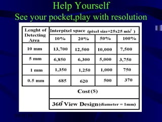
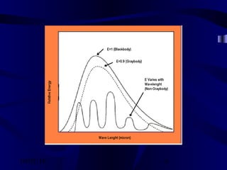
Cost-Effectiveness of different Options
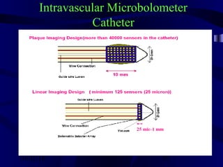
1. Plaque Imaging Model(10 mm option)
Cost:
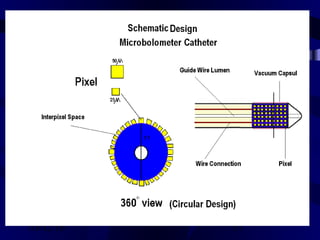
Area of each Pixel = 25 x 25 =625 µ²
Detecting Area= [10 x (2 x 3.14 x (½)] = 31.4 x 10⁶µ²
Interpixels Area = 10% of each pixel area
Net Detecting Area=28.26 x 10⁶µ²
The Number of Pixels = 45670 ~ 45500 spots
(It is far more than enough because each fiber optic
bundle can visualize 100 spots of the plaque)
Advantages: Instantaneous Viewing of the Plaque
Drawback: High Cost, Inflexibility
(Minimal Bending Radius)](https://image.slidesharecdn.com/qgsntih1qsocsz2donoj-signature-fdd98666ab8a3121f485da35cb0ca98b05e9b7f147f04f41c8b78366d2ae96a7-poli-161002234618/85/080-intravascular-micro-bolometer-catheter-66-320.jpg)
![10/02/16 67
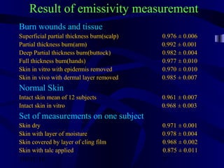
Cost-Effectiveness of Different options
2. Linear Imaging Model(1 mm)
Cost:
Area of each Pixel = 25 x 25 =625 µ²
Detecting Area = [1 x (2 x 3.14 x (½)] = 3.14 x 10⁶µ²
Interpixels Area = 10% of each pixel area
Net Detecting Area = 2.826 x 10⁶µ²
The Number of Pixels =4560 ~ 4500
Advantages:Low Cost, Flexible
Drawback:Needs software for the image
reconstruction](https://image.slidesharecdn.com/qgsntih1qsocsz2donoj-signature-fdd98666ab8a3121f485da35cb0ca98b05e9b7f147f04f41c8b78366d2ae96a7-poli-161002234618/85/080-intravascular-micro-bolometer-catheter-67-320.jpg)